2015 MERCEDES-BENZ GLC SUV height
[x] Cancel search: heightPage 274 of 497
This view assists you in estimating the dis-
tance to the vehicle behind you.
i This setting can also be selected as an
enlarged front view.
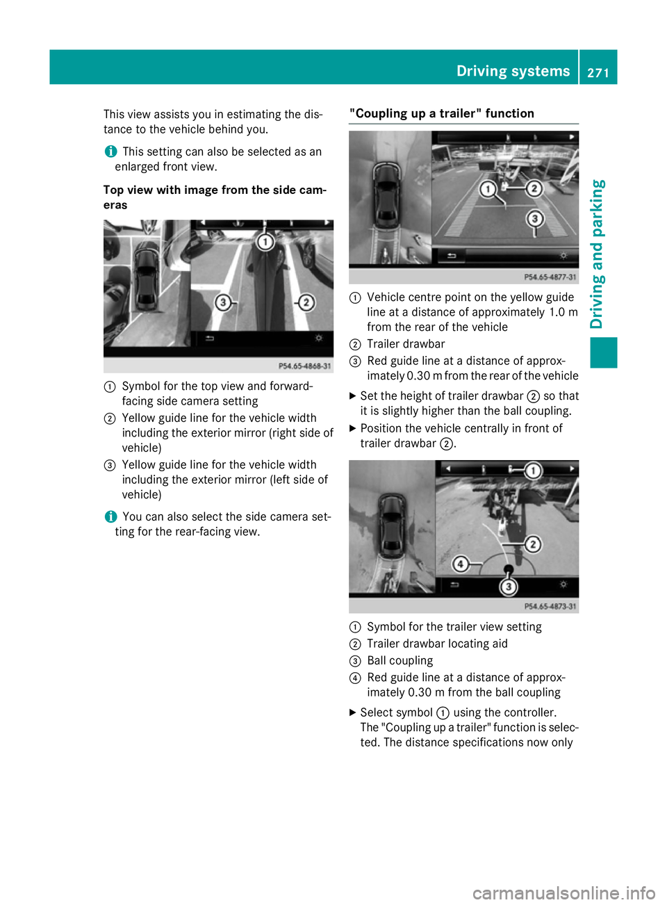
Top view with image from the side cam-
eras :
Symbol for the top view and forward-
facing side camera setting
; Yellow guide line for the vehicle width
including the exterior mirror (right side of vehicle)
= Yellow guide line for the vehicle width
including the exterior mirror (left side of
vehicle)
i You can also select the side camera set-
ting for the rear-facing view. "Coupling up a trailer" function :
Vehicle centre point on the yellow guide
line at a distance of approximately 1.0 m
from the rear of the vehicle
; Trailer drawbar
= Red guide line at a distance of approx-
imately 0.30 mfrom the rear of the vehicle
X Set the height of trailer drawbar ;so that
it is slightly higher than the ball coupling.
X Position the vehicle centrally in front of
trailer drawbar ;. :
Symbol for the trailer view setting
; Trailer drawbar locating aid
= Ball coupling
? Red guide line at a distance of approx-
imately 0.30 m from the ball coupling
X Select symbol :using the controller.
The "Coupling up a trailer" function is selec- ted. The distance specifications now only Driving systems
271Driving and parking Z
Page 306 of 497
Make sure that the following values are not
exceeded:
R the permissible trailer drawbar noseweight
R the permissible trailer load
R the permissible rear axle load of the towing
vehicle
R the maximum permissible gross vehicle
weight of both the towing vehicle and the
trailer
The applicable permissible values, which
must not be exceeded, can be found:
R in your vehicle documents
R on the identification plates of the trailer tow
hitch and the trailer
R on the vehicle identification plate
If the values differ, the lowest value applies.
You will find the values approved by the man-
ufacturer on the vehicle identification plates
and those for the towing vehicle under "Tech- nical data" (Y page 491). G
WARNING
If you release the ball coupling or it does not
engage correctly when folding in, it will swing out. Within pivoting range of the ball coupling,
there is an increased risk of an accident and
injury.
Only release the ball coupling if the pivoting
range is unobstructed. Always make sure that the ball coupling engages when folding in.
When reversing the vehicle towards the
trailer, make sure there is nobody between
the trailer and the vehicle.
Couple and uncouple the trailer carefully. If
you do not couple the trailer to the towing
vehicle correctly, the trailer could become
detached.
When towing a trailer, your vehicle's handling
characteristics will be different in comparison to when driving without a trailer.
The vehicle/trailer combination:
R is heavier
R is restricted in its acceleration and gradi-
ent-climbing capability R
has an increased braking distance
R is affected more by strong crosswinds
R demands more sensitive steering
R has a larger turning circle
This can impair the vehicle's handling char-
acteristics. Adapt your driving style accord-
ingly. Maintain a safe distance. Drive care-
fully.
When towing a trailer, always adjust your
speed to the current road and weather con-
ditions. Do not exceed the maximum permis-
sible speed for your vehicle/trailer combina-
tion. Notes on towing a trailer
General notes When towing a trailer, set the tyre pressure on
the rear axle of the towing vehicle for the
maximum load. Further information on the
tyre pressure table in the fuel filler flap
(Y page 458).
On vehicles without level control, the height
of the ball coupling will alter according to the load placed on the vehicle. If necessary, use a
trailer with a height-adjustable drawbar.
You will find fitting dimensions and loads
under "Technical data" (Y page 490).
Driving tips Observe the notes on ESP
®
trailer stabilisa-
tion (Y page 86).
The maximum permissible speed for vehicle/
trailer combinations depends on the type of
trailer. Before beginning the journey, check
the trailer's documents to see what the max- imum permitted speed is. Observe the legally
prescribed maximum speed in the relevant
country.
For certain Mercedes-Benz vehicles, the max-
imum permissible rear axle load is increased
when towing a trailer. See the "Technical
data" section to find out whether this applies to your vehicle (Y page 491). If you utilise any Towing a trailer
303Driving and parking Z
Page 334 of 497
X
Confirm by pressing aon the steering
wheel.
X Press :or9 to select the Head-up
Head-up
display
display submenu.
X Press ato confirm.
X Select Display content
Display content with: or
9.
X Press ato confirm.
A graphic selection list appears.
X Press :or9 to select the desired
display.
X Press the abutton to confirm the selec-
tion.
Further information on navigation can be
found in the separate Audio 20 or COMAND
Online operating instructions.
Further information about Traffic Sign Assist
(Y page 274).
Setting the position
You can adjust the position of the head-up
display on the windscreen. You can compen-
sate for height differences if the seat posi-
tions are changed, for example.
X Switch on the head-up display
(Y page 316).
X Press òon the steering wheel to open
the menu list.
X Press :or9 on the steering wheel
to select the Settings
Settings menu.
X Confirm by pressing aon the steering
wheel.
X Use : or9 to select the Head-up
Head-up
display
display submenu.
X Press ato confirm.
X Using :or9, select the Position Position
function.
X Press ato save the setting.
X Press :or9 to adjust the position
to a level from Level +5
Level +5toLevel -5
Level -5.
X Press aor% to save the setting.
Using the Memory function, you can save and call up the set position of the head-up display
as a single memory preset (Y page 134).Adjusting the brightness
The brightness of the head-up display is auto-
matically adjusted to the surrounding light
conditions. You can also individually adjust
the brightness of the head-up display.
X Switch on the head-up display
(Y page 316).
X Press òon the steering wheel to open
the menu list.
X Press :or9 on the steering wheel
to select the Settings
Settings menu.
X Confirm by pressing aon the steering
wheel.
X Use : or9 to select the Head-up
Head-up
display display submenu.
X Press ato confirm.
X Using :or9, select the Bright‐
Bright‐
ness
ness function.
X Press the abutton to save the setting.
X Press :or9 to adjust the bright-
ness to a level from Level +5
Level +5(bright) to
Level -5
Level -5 (dark).
X Press the aor% button to save the
setting.
Light submenu Switching the Intelligent Light System
on/off
X Press òon the steering wheel to open
the menu list.
X Press :or9 on the steering wheel
to select the Settings Settingsmenu.
X Confirm by pressing aon the steering
wheel.
X Press :or9 to select the Lights Lights
submenu.
X Press ato confirm.
X Using :or9, select the Intelli‐ Intelli‐
gent Light System
gent Light System function.
If the Intelligent Light System Intelligent Light System func-
tion has been switched on, the cone of light Menus and submenus
331On-board computer and displays Z
Page 419 of 497
Closing the bonnet
X
Lower the bonnet and let it fall from a
height of approximately 20 cm.
X Check that the bonnet has engaged prop-
erly.
If the bonnet can be raised slightly, it is not
properly engaged. Open it again and close
it with a little more force. Radiator
Do not cover up the radiator. Do not use ther-
mal mats, insect protection covers or any-
thing similar. Doing so can cause the Onboard Diagnostics System to display inaccurate val-
ues. Some of these values are legally required
and must always be correct. Engine oil
General notes Depending on your driving style, the vehicle
consumes up to 0.8 litres of oil per 1000 km.
The oil consumption may be higher than this
when the vehicle is new or if you frequently
drive at high engine speeds.
Depending on the engine, the oil dipstick may
be installed at a different location.
When checking the oil level:
R park the vehicle on a level surface
R the engine should be switched off for
approximately five minutes if the engine is
at normal operating temperature
R if the engine is not at normal operating
temperature, e.g. if the engine was only
started briefly, wait approximately
30 minutes before carrying out the meas-
urement Checking the oil level using the oil dip-
stick G
WARNING
Certain components in the engine compart-
ment could be very hot, e.g. the engine, the
radiator and parts of the exhaust system.
There is a risk of injury when accessing the
engine compartment.
As far as possible, allow the engine to cool
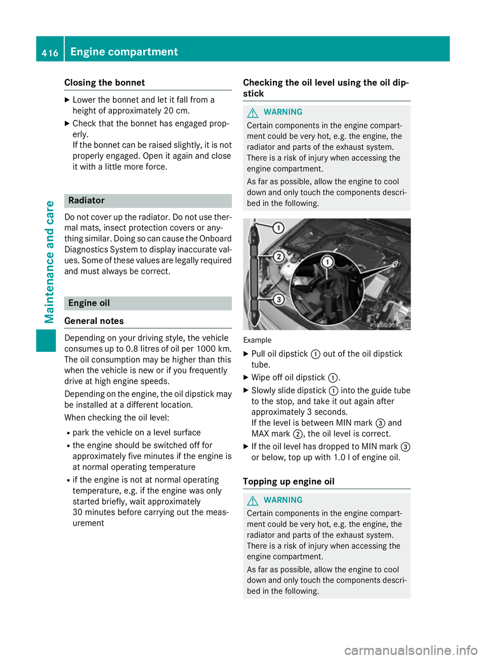
down and only touch the components descri- bed in the following. Example
X Pull oil dipstick :out of the oil dipstick
tube.
X Wipe off oil dipstick :.
X Slowly slide dipstick :into the guide tube
to the stop, and take it out again after
approximately 3 seconds.
If the level is between MIN mark =and
MAX mark ;, the oil level is correct.
X If the oil level has dropped to MIN mark =
or below, top up with 1.0 l of engine oil.
Topping up engine oil G
WARNING
Certain components in the engine compart-
ment could be very hot, e.g. the engine, the
radiator and parts of the exhaust system.
There is a risk of injury when accessing the
engine compartment.
As far as possible, allow the engine to cool
down and only touch the components descri- bed in the following. 416
Engine compartmentMaintenance and care
Page 468 of 497
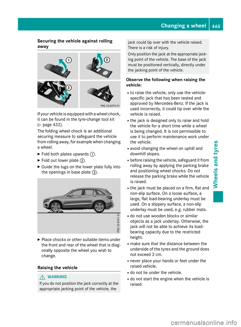
Securing the vehicle against rolling
away
If your vehicle is equipped with a wheel chock,
it can be found in the tyre-change tool kit
(Y page 432).
The folding wheel chock is an additional
securing measure to safeguard the vehicle
from rolling away, for example when changing
a wheel.
X Fold both plates upwards :.
X Fold out lower plate ;.
X Guide the lugs on the lower plate fully into
the openings in base plate =.X
Place chocks or other suitable items under
the front and rear of the wheel that is diag-
onally opposite the wheel you wish to
change.
Raising the vehicle G
WARNING
If you do not position the jack correctly at the appropriate jacking point of the vehicle, the jack could tip over with the vehicle raised.
There is a risk of injury.
Only position the jack at the appropriate jack-
ing point of the vehicle. The base of the jack
must be positioned vertically, directly under
the jacking point of the vehicle.
Observe the following when raising the
vehicle:
R to raise the vehicle, only use the vehicle-
specific jack that has been tested and
approved by Mercedes-Benz. If the jack is
used incorrectly, it could tip over while the vehicle is raised.
R the jack is designed only to raise and hold
the vehicle for a short time while a wheel
is being changed. It is not permissible to
use it to perform maintenance work under
the vehicle.
R avoid changing the wheel on uphill and
downhill slopes.
R before raising the vehicle, safeguard it from
rolling away by applying the parking brake
and positioning wheel chocks. Do not
release the parking brake while the vehicle
is raised.
R the jack must be placed on a firm, flat and
non-slip surface. On a loose surface, a
large, flat load-bearing underlay must be
used. On a slippery surface, a non-slip
underlay must be used, e.g. rubber mats.
R do not use wooden blocks or similar
objects as a jack underlay. Otherwise, the
jack will not be able to achieve its load-
bearing capacity due to the restricted
height.
R make sure that the distance between the
underside of the tyres and the ground does
not exceed 3 cm.
R never place your hands or feet under the
raised vehicle.
R do not lie under the vehicle.
R do not start the engine when the vehicle is
raised. Changing a wheel
465Wheels and tyres Z
Page 491 of 497
!
Only the washer fluids SummerFit and
WinterFit can be mixed. Otherwise, the
spraying nozzles could become blocked.
Comply with the important safety notes for
service products when handling washer fluid
(Y page 480).
At temperatures above freezing:
X Fill the washer fluid reservoir with a mixture
of water and washer fluid, e.g. MB Sum-
merFit.
Mix 1 part MB SummerFit to 100 parts water.
At temperatures below freezing:
X Fill the washer fluid reservoir with a mixture
of water and washer fluid, e.g. MB Winter-
Fit.
For the correct mixing ratio refer to the
information on the antifreeze reservoir.
i Add washer fluid concentrate, e.g. MB
SummerFit or MB WinterFit, to the washer
fluid all year round. Vehicle data
General notes
Please note that for the specified vehicle
data: R the heights specified may vary as a result
of:
- tyres
- load
- condition of the suspension
- optional equipment
R optional equipment reduces the maximum
payload
R Vehicle-specific weight information can be
found on the vehicle identification plate
(Y page 480).
R only for certain countries: you can find vehi-
cle-specific vehicle data in the COC docu-
ments (CERTIFICATE OF CONFORMITY).
These documents are delivered with your
vehicle. Observe the information relating to level con-
trol:
R AIR BODY CONTROL (Y page 252)
R Off-Road Engineering package
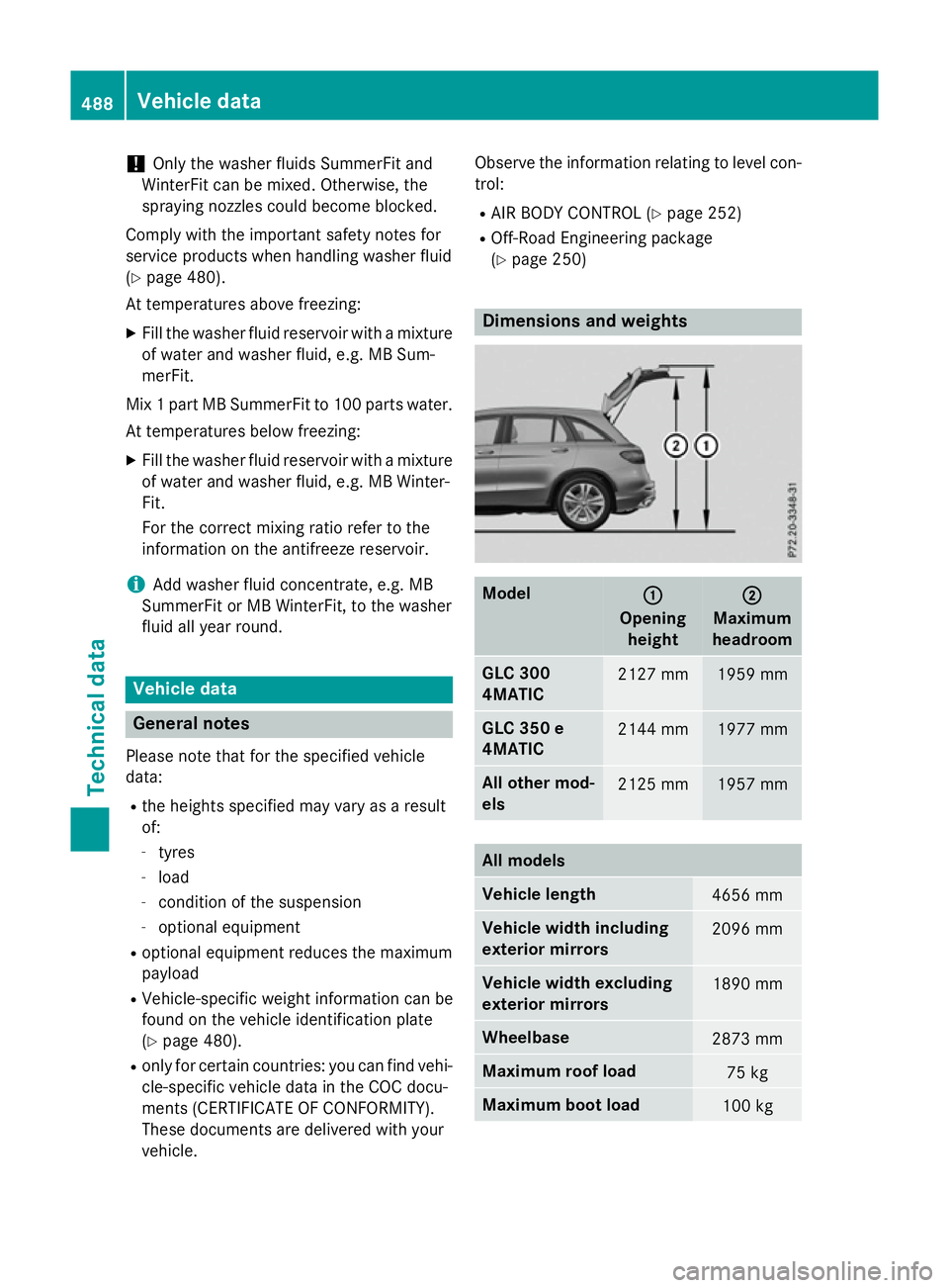
(Y page 250) Dimensions and weights
Model
: :
Opening height ;
;
Maximum
headroom GLC 300
4MATIC
2127 mm 1959 mm
GLC 350 e
4MATIC
2144 mm 1977 mm
All other mod-
els
2125 mm 1957 mm
All models
Vehicle length
4656 mm
Vehicle width including
exterior mirrors
2096 mm
Vehicle width excluding
exterior mirrors
1890 mm
Wheelbase
2873 mm
Maximum roof load
75 kg
Maximum boot load
100 kg488
Vehicle dataTechnical data
Page 492 of 497
Model Vehicle
height GLC 300 4MATIC
1645 mm
GLC 350 e 4MATIC
1661 mm
All other models
1642 mm
Vehicle data for off-road driving
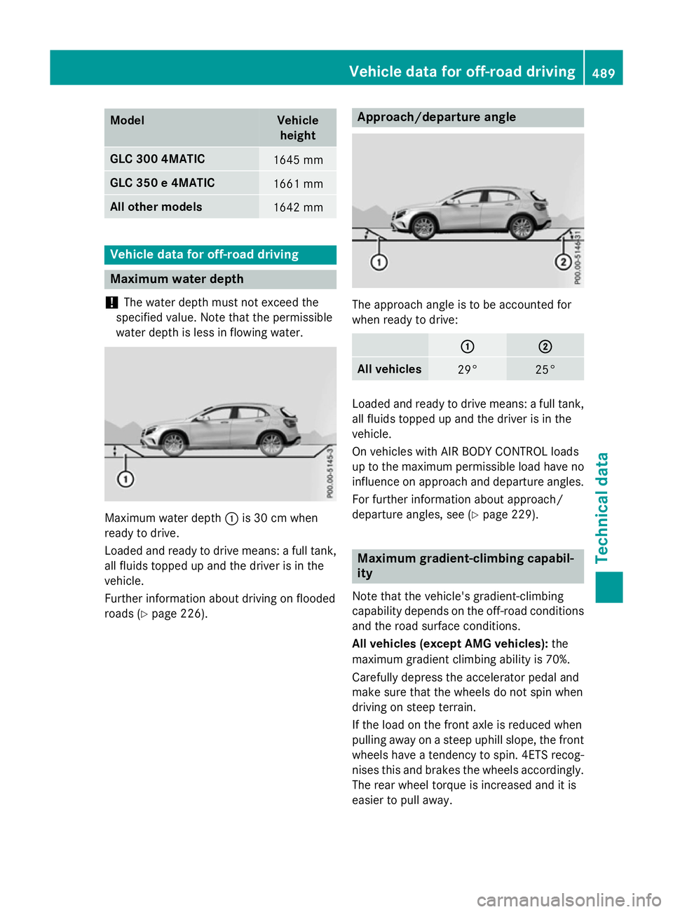
Maximum water depth
! The water depth must not exceed the
specified value. Note that the permissible
water depth is less in flowing water. Maximum water depth
:is 30 cm when
ready to drive.
Loaded and ready to drive means: a full tank, all fluids topped up and the driver is in the
vehicle.
Further information about driving on flooded
roads (Y page 226). Approach/departure angle
The approach angle is to be accounted for
when ready to drive:
: : ;
;
All vehicles
29° 25°
Loaded and ready to drive means: a full tank,
all fluids topped up and the driver is in the
vehicle.
On vehicles with AIR BODY CONTROL loads
up to the maximum permissible load have no
influence on approach and departure angles.
For further information about approach/
departure angles, see (Y page 229). Maximum gradient-climbing capabil-
ity
Note that the vehicle's gradient-climbing
capability depends on the off-road conditions and the road surface conditions.
All vehicles (except AMG vehicles): the
maximum gradient climbing ability is 70%.
Carefully depress the accelerator pedal and
make sure that the wheels do not spin when
driving on steep terrain.
If the load on the front axle is reduced when
pulling away on a steep uphill slope, the front
wheels have a tendency to spin. 4ETS recog- nises this and brakes the wheels accordingly. The rear wheel torque is increased and it is
easier to pull away. Vehicle data for off-road driving
489Technical data Z