2015 MERCEDES-BENZ GLC SUV tow bar
[x] Cancel search: tow barPage 286 of 497
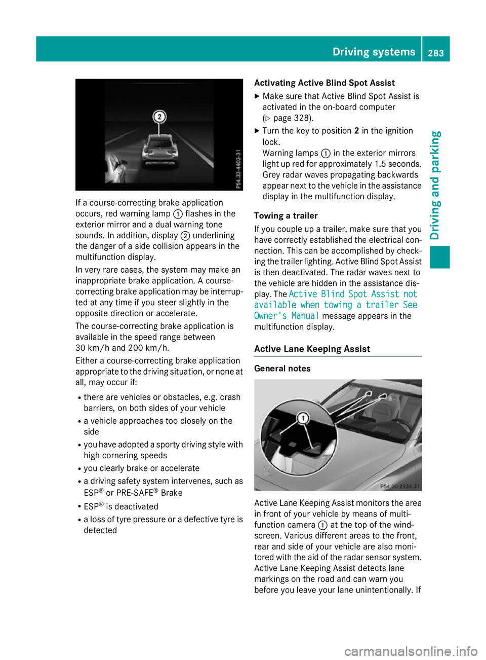
If a course-correcting brake application
occurs, red warning lamp :flashes in the
exterior mirror and a dual warning tone
sounds. In addition, display ;underlining
the danger of a side collision appears in the
multifunction display.
In very rare cases, the system may make an
inappropriate brake application. A course-
correcting brake application may be interrup-
ted at any time if you steer slightly in the
opposite direction or accelerate.
The course-correcting brake application is
available in the speed range between
30 km/h and 200 km/h.
Either a course-correcting brake application
appropriate to the driving situation, or none at all, may occur if:
R there are vehicles or obstacles, e.g. crash
barriers, on both sides of your vehicle
R a vehicle approaches too closely on the
side
R you have adopted a sporty driving style with
high cornering speeds
R you clearly brake or accelerate
R a driving safety system intervenes, such as
ESP ®
or PRE-SAFE ®
Brake
R ESP ®
is deactivated
R a loss of tyre pressure or a defective tyre is
detected Activating Active Blind Spot Assist
X Make sure that Active Blind Spot Assist is
activated in the on-board computer
(Y page 328).
X Turn the key to position 2in the ignition
lock.
Warning lamps :in the exterior mirrors
light up red for approximately 1.5 seconds. Grey radar waves propagating backwards
appear next to the vehicle in the assistance
display in the multifunction display.
Towing a trailer
If you couple up a trailer, make sure that you have correctly established the electrical con-
nection. This can be accomplished by check- ing the trailer lighting. Active Blind Spot Assist
is then deactivated. The radar waves next to
the vehicle are hidden in the assistance dis-
play. The Active
Active Blind BlindSpot
SpotAssist
Assist not
not
available
available when
whentowing
towing a
atrailer
trailer See
See
Owner's Manual
Owner's Manual message appears in the
multifunction display.
Active Lane Keeping Assist General notes
Active Lane Keeping Assist monitors the area
in front of your vehicle by means of multi-
function camera :at the top of the wind-
screen. Various different areas to the front,
rear and side of your vehicle are also moni-
tored with the aid of the radar sensor system. Active Lane Keeping Assist detects lane
markings on the road and can warn you
before you leave your lane unintentionally. If Driving systems
283Driving and parking Z
Page 305 of 497
Hybrid drive system
Problem
Possible causes/consequences and
M
MSolutions The hybrid drive system
has been switched off
automatically. You have been in an accident.
The hybrid drive system remains switched off if:
R the internal combustion engine cannot be restarted after a few
seconds.
R the red 6restraint system warning lamp in the instrument
cluster is lit.
X Consult a qualified specialist workshop. The hybrid drive system
has been switched off
automatically. The mul-
tifunction display also
shows a display mes-
sage. An electrical short circuit has occurred in the hybrid drive system
or an electrical connection has been disconnected.
X Observe the additional display messages in the multifunction
display (Y page 335).
X Consult a qualified specialist workshop. Towing a trailer
Important safety notes
G
WARNING
You could lose control of the vehicle/trailer
combination if it begins to swerve. The vehi-
cle/trailer combination could even overturn.
There is a risk of an accident.
On no account should you attempt to
straighten out the vehicle/trailer combina-
tion by increasing speed. Decrease your
speed and do not countersteer. Brake if nec-
essary. G
WARNING
If the maximum the permissible load for a car- rier system is exceeded, the carrier could
come loose from the vehicle and endanger
other road users. There is a risk of an accident and injury.
Never exceed the permissible noseweight
when using a carrier. Exceeding the maximum permissible nose-
weight of the trailer drawbar on the ball cou-
pling may cause damage to the following:
R your vehicle
R the trailer
R the ball coupling
R trailer tow hitch
The vehicle/trailer combination could
become unstable.
If the noseweight used is lower than the min- imum permissible noseweight, the vehicle/
trailer combination could also become unsta- ble.
To avoid hazardous situations:
R make sure to check the noseweight before
each journey
R use a drawbar noseweight as close as pos-
sible to the maximum noseweight
R do not exceed the maximum permissible
noseweight
R do not use a noseweight lower than the
minimum noseweight 302
Towing a trailerDriving and parking
Page 306 of 497
Make sure that the following values are not
exceeded:
R the permissible trailer drawbar noseweight
R the permissible trailer load
R the permissible rear axle load of the towing
vehicle
R the maximum permissible gross vehicle
weight of both the towing vehicle and the
trailer
The applicable permissible values, which
must not be exceeded, can be found:
R in your vehicle documents
R on the identification plates of the trailer tow
hitch and the trailer
R on the vehicle identification plate
If the values differ, the lowest value applies.
You will find the values approved by the man-
ufacturer on the vehicle identification plates
and those for the towing vehicle under "Tech- nical data" (Y page 491). G
WARNING
If you release the ball coupling or it does not
engage correctly when folding in, it will swing out. Within pivoting range of the ball coupling,
there is an increased risk of an accident and
injury.
Only release the ball coupling if the pivoting
range is unobstructed. Always make sure that the ball coupling engages when folding in.
When reversing the vehicle towards the
trailer, make sure there is nobody between
the trailer and the vehicle.
Couple and uncouple the trailer carefully. If
you do not couple the trailer to the towing
vehicle correctly, the trailer could become
detached.
When towing a trailer, your vehicle's handling
characteristics will be different in comparison to when driving without a trailer.
The vehicle/trailer combination:
R is heavier
R is restricted in its acceleration and gradi-
ent-climbing capability R
has an increased braking distance
R is affected more by strong crosswinds
R demands more sensitive steering
R has a larger turning circle
This can impair the vehicle's handling char-
acteristics. Adapt your driving style accord-
ingly. Maintain a safe distance. Drive care-
fully.
When towing a trailer, always adjust your
speed to the current road and weather con-
ditions. Do not exceed the maximum permis-
sible speed for your vehicle/trailer combina-
tion. Notes on towing a trailer
General notes When towing a trailer, set the tyre pressure on
the rear axle of the towing vehicle for the
maximum load. Further information on the
tyre pressure table in the fuel filler flap
(Y page 458).
On vehicles without level control, the height
of the ball coupling will alter according to the load placed on the vehicle. If necessary, use a
trailer with a height-adjustable drawbar.
You will find fitting dimensions and loads
under "Technical data" (Y page 490).
Driving tips Observe the notes on ESP
®
trailer stabilisa-
tion (Y page 86).
The maximum permissible speed for vehicle/
trailer combinations depends on the type of
trailer. Before beginning the journey, check
the trailer's documents to see what the max- imum permitted speed is. Observe the legally
prescribed maximum speed in the relevant
country.
For certain Mercedes-Benz vehicles, the max-
imum permissible rear axle load is increased
when towing a trailer. See the "Technical
data" section to find out whether this applies to your vehicle (Y page 491). If you utilise any Towing a trailer
303Driving and parking Z
Page 309 of 497
Uncoupling a trailer
G
WARNING
If you uncouple a trailer with an engaged over- run brake, you could trap your hand between
the vehicle and the trailer drawbar. This poses a risk of injury.
Do not uncouple a trailer with an engaged
overrun brake. G
WARNING
Vehicles with level control:
If you disconnect the trailer cable, the vehicle is lowered. This can cause you or others to
become trapped between the vehicle body
and tyres, or underneath the vehicle. This
poses a risk of injury.
Make sure that no-one is in the immediate
vicinity of the wheel arch or underneath the
vehicle when disconnecting the trailer cable.
! Do not disconnect a trailer with an
engaged overrun brake. Otherwise, your
vehicle could be damaged by the rebound- ing of the overrun brake.
! Remove the installed adapter cable
before folding in the ball coupling. Other-
wise, damage may occur to the rear
bumper and the adapter cable.
X Make sure that the transmission is in posi-
tion P.
X Apply the electric parking brake.
X Secure the trailer against rolling away.
X Remove the trailer cable and decouple the
trailer. Swinging the ball coupling in
! Do not attempt to speed the up the swing-
out procedure by applying additional pres-
sure with your foot. The system could oth-
erwise be mechanically damaged.
Swing the ball coupling back in using the
switch on the driver's door or tailgate, if you
are not using the trailer tow hitch. Only release the ball coupling when its range
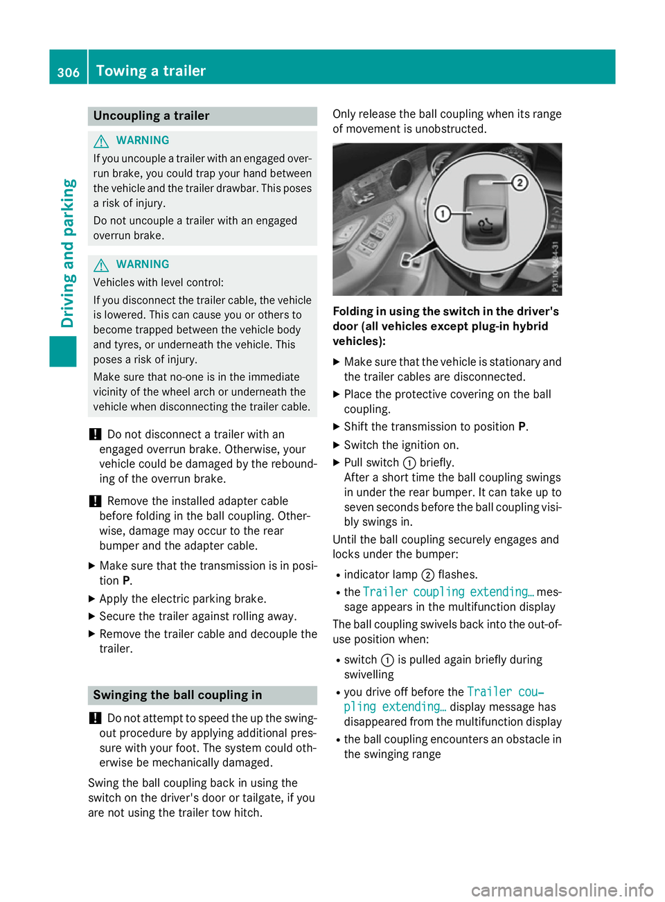
of movement is unobstructed. Folding in using the switch in the driver's
door (all vehicles except plug-in hybrid
vehicles):
X Make sure that the vehicle is stationary and
the trailer cables are disconnected.
X Place the protective covering on the ball
coupling.
X Shift the transmission to position P.
X Switch the ignition on.
X Pull switch :briefly.
After a short time the ball coupling swings
in under the rear bumper. It can take up to seven seconds before the ball coupling visi-bly swings in.
Until the ball coupling securely engages and
locks under the bumper:
R indicator lamp ;flashes.
R the Trailer
Trailer coupling coupling extending…
extending… mes-
sage appears in the multifunction display
The ball coupling swivels back into the out-of-
use position when:
R switch :is pulled again briefly during
swivelling
R you drive off before the Trailer cou‐
Trailer cou‐
pling extending…
pling extending… display message has
disappeared from the multifunction display
R the ball coupling encounters an obstacle in
the swinging range 306
Towing a trailerDriving and parking
Page 399 of 497
X
To lock: fold the left and centre seat backr-
ests forward. Make sure that the centre and
left seat backrests are engaged and joined together.
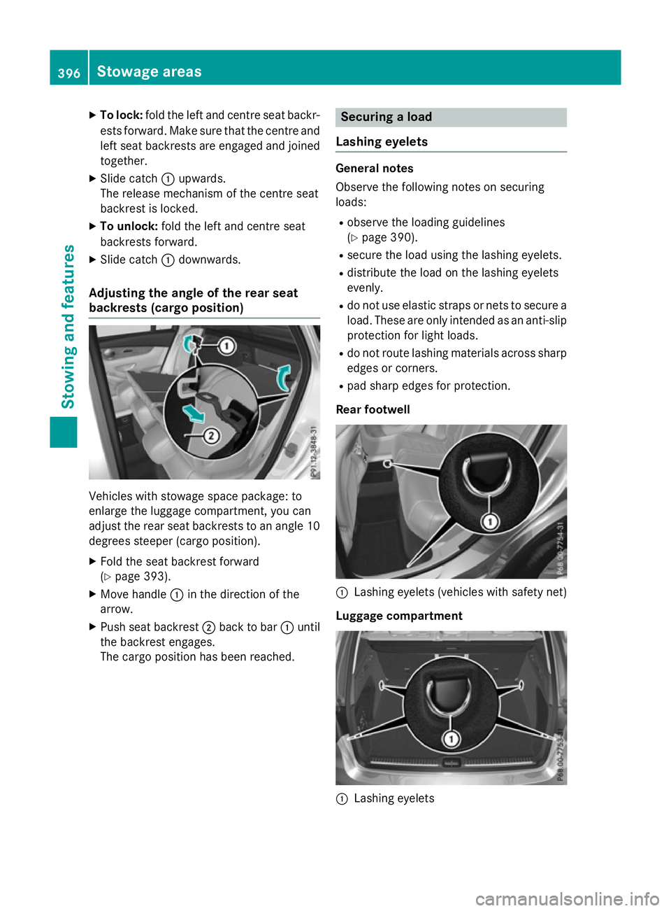
X Slide catch :upwards.
The release mechanism of the centre seat
backrest is locked.
X To unlock: fold the left and centre seat
backrests forward.
X Slide catch :downwards.
Adjusting the angle of the rear seat
backrests (cargo position) Vehicles with stowage space package: to
enlarge the luggage compartment, you can
adjust the rear seat backrests to an angle 10 degrees steeper (cargo position).
X Fold the seat backrest forward
(Y page 393).
X Move handle :in the direction of the
arrow.
X Push seat backrest ;back to bar :until
the backrest engages.
The cargo position has been reached. Securing a load
Lashing eyelets General notes
Observe the following notes on securing
loads:
R observe the loading guidelines
(Y page 390).
R secure the load using the lashing eyelets.
R distribute the load on the lashing eyelets
evenly.
R do not use elastic straps or nets to secure a
load. These are only intended as an anti-slip protection for light loads.
R do not route lashing materials across sharp
edges or corners.
R pad sharp edges for protection.
Rear footwell :
Lashing eyelets (vehicles with safety net)
Luggage compartment :
Lashing eyelets 396
Stowage areasSto
wing an d features
Page 429 of 497
X
Make sure that the vehicle is stationary and
that the key is in position 2in the ignition
lock.
X To open the cover of the 360° camera:
with COMAND Online or Audio 20 activa-
ted, call up the vehicle menu: press the
Ñ button.
X To switch to the menu bar: slide 6the
controller.
X To select System settings
System settings: turn and
press the controller.
X To select the 360° 360°camera
camera: turn and press
the controller.
X To select Open camera cover
Open camera cover: turn and
press the controller.
The cover of the 360° camera opens.
X To clean the 360° camera: clean camera
lens :with clean water and a soft cloth.
If you drive at speeds above 30 km/h or with the key in position 0or 1in the ignition lock,
the cover of the 360° camera closes auto-
matically.
Cleaning the exhaust tail pipes G
WARNING
The exhaust tail pipe and tail pipe trim can
become very hot. If you come into contact
with these parts of the vehicle, you could burn
yourself. There is a risk of injury.
Always be particularly careful around the
exhaust tail pipe and the tail pipe trim. Allow
these components to cool down before touch-
ing them.
! Do not clean the exhaust pipe with acid-
based cleaning agents, such as sanitary
cleanser or wheel cleaner.
Impurities combined with the effects of road
grit and corrosive environmental factors may cause flash rust to form on the surface. You
can restore the original shine of the exhaust
pipe by cleaning it regularly, especially in win- ter and after washing the vehicle. X
Clean the exhaust pipe with a care product
tested and approved by Mercedes-Benz.
Cleaning the trailer tow hitch H
Environmental note
Dispose of oily and greasy cloths in an envi-
ronmentally-responsible manner.
! Do not clean the ball coupling with a high-
pressure cleaner. Do not use solvents.
! Please note the care instructions in the
trailer coupling manufacturer's operating
instructions.
The ball coupling must be cleaned if it
becomes dirty or corroded. X Remove rust on the ball, e.g. with a wire
brush.
X Remove dirt with a clean, lint-free cloth or a
brush.
X After cleaning, lightly oil or grease the ball
coupling.
X Check that the vehicle's trailer tow hitch is
working properly.
i You can also have the maintenance work
on the ball coupling and the trailer tow hitch
carried out by a qualified specialist work-
shop. Interior care
Cleaning the display !
For cleaning, do not use any of the fol-
lowing:
R alcohol-based thinner or petrol
R abrasive cleaning agents
R commercially-available household clean-
ing agents
These may damage the display surface. Do not put pressure on the display surface
when cleaning. This could lead to irrepara-
ble damage to the display. 426
CareMaintenance and care
Page 436 of 497
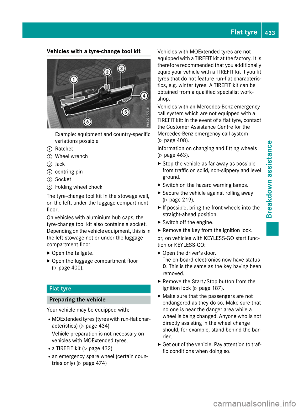
Vehicles with a tyre-change tool kit
Example: equipment and country-specific
variations possible
: Ratchet
; Wheel wrench
= Jack
? centring pin
A Socket
B Folding wheel chock
The tyre-change tool kit in the stowage well,
on the left, under the luggage compartment
floor.
On vehicles with aluminium hub caps, the
tyre-change tool kit also contains a socket.
Depending on the vehicle equipment, this is in the left stowage net or under the luggage
compartment floor.
X Open the tailgate.
X Open the luggage compartment floor
(Y page 400). Flat tyre
Preparing the vehicle
Your vehicle may be equipped with: R MOExtended tyres (tyres with run-flat char-
acteristics) (Y page 434)
Vehicle preparation is not necessary on
vehicles with MOExtended tyres.
R a TIREFIT kit (Y page 432)
R an emergency spare wheel (certain coun-
tries only) (Y page 474) Vehicles with MOExtended tyres are not
equipped with a TIREFIT kit at the factory. It is
therefore recommended that you additionallyequip your vehicle with a TIREFIT kit if you fit tyres that do not feature run-flat characteris-
tics, e.g. winter tyres. A TIREFIT kit can be
obtained from a qualified specialist work-
shop.
Vehicles with an Mercedes-Benz emergency
call system which are not equipped with a
TIREFIT kit: in the event of a flat tyre, contact
the Customer Assistance Centre for the
Mercedes-Benz emergency call system
(Y page 408).
Information on changing and fitting wheels
(Y page 463).
X Stop the vehicle as far away as possible
from traffic on solid, non-slippery and level
ground.
X Switch on the hazard warning lamps.
X Secure the vehicle against rolling away
(Y page 219).
X If possible, bring the front wheels into the
straight-ahead position.
X Switch off the engine.
X Remove the key from the ignition lock.
or, on vehicles with KEYLESS-GO start func-
tion or KEYLESS ‑GO:
X Open the driver's door.
The on-board electronics now have status
0. This is the same as the key having been
removed.
X Remove the Start/Stop button from the
ignition lock (Y page 187).
X Make sure that the passengers are not
endangered as they do so. Make sure that
no one is near the danger area while a
wheel is being changed. Anyone who is not
directly assisting in the wheel change
should, for example, stand behind the bar-
rier.
X Get out of the vehicle. Pay attention to traf-
fic conditions when doing so. Flat tyre
433Breakdown assis tance
Page 440 of 497
impair the vehicle's braking and driving char-
acteristics. There is a risk of accident.
Do not continue driving. Contact a qualified
specialist workshop.
Tyre pressure reached G
WARNING
A tyre temporarily sealed with tyre sealant
impairs the driving characteristics and is not
suitable for higher speeds. There is a risk of
accident.
You should therefore adapt your driving style
accordingly and drive carefully. Do not exceed the specified maximum speed with a tyre that
has been repaired using tyre sealant.
The maximum permissible speed for a tyre
sealed with tyre sealant is 80 km/h. The
upper part of the TIREFIT sticker must be
affixed to the instrument cluster where it will be easily seen by the driver.
! After use, excess tyre sealant may run out
of the filler hose. This could cause stains.
Therefore, place the tyre sealant bottle with
filler hose in the plastic bag which is con-
tained the TIREFIT kit. H
Environmental note
Have the used tyre sealant bottle disposed of
professionally, e.g. at a qualified specialist
workshop.
If a tyre pressure of 180 kPa (1.8 bar/26 psi)
has been attained after five minutes:
X Switch off the tyre inflation compressor.
X Unscrew the filler hose from the valve of
the faulty tyre. X
Stow the tyre sealant bottle, the tyre infla-
tion compressor and the warning triangle.
X Pull away immediately.
X Stop after driving for approximately ten
minutes and check the tyre pressure with
the tyre inflation compressor.
The tyre pressure must now be at least
130 kPa (1.3 bar/19 psi). G
WARNING
If the required tyre pressure is not reached
after driving for a short period, the tyre is too badly damaged. The tyre sealant cannot
repair the tyre in this instance. Damaged tyres and a tyre pressure that is too low can signif-
icantly impair the vehicle's braking and driv-
ing characteristics. There is a risk of accident.
Do not continue driving. Contact a qualified
specialist workshop.
i In your vehicle, you will find a sticker with
the Mercedes-Benz Service24h telephone
number, e.g. on the B-pillar on the driver's
side.
X Correct the tyre pressure if it is still at least
130 kPa (1.3 bar/19 psi). See the tyre
pressure table on the fuel filler flap for val-
ues.
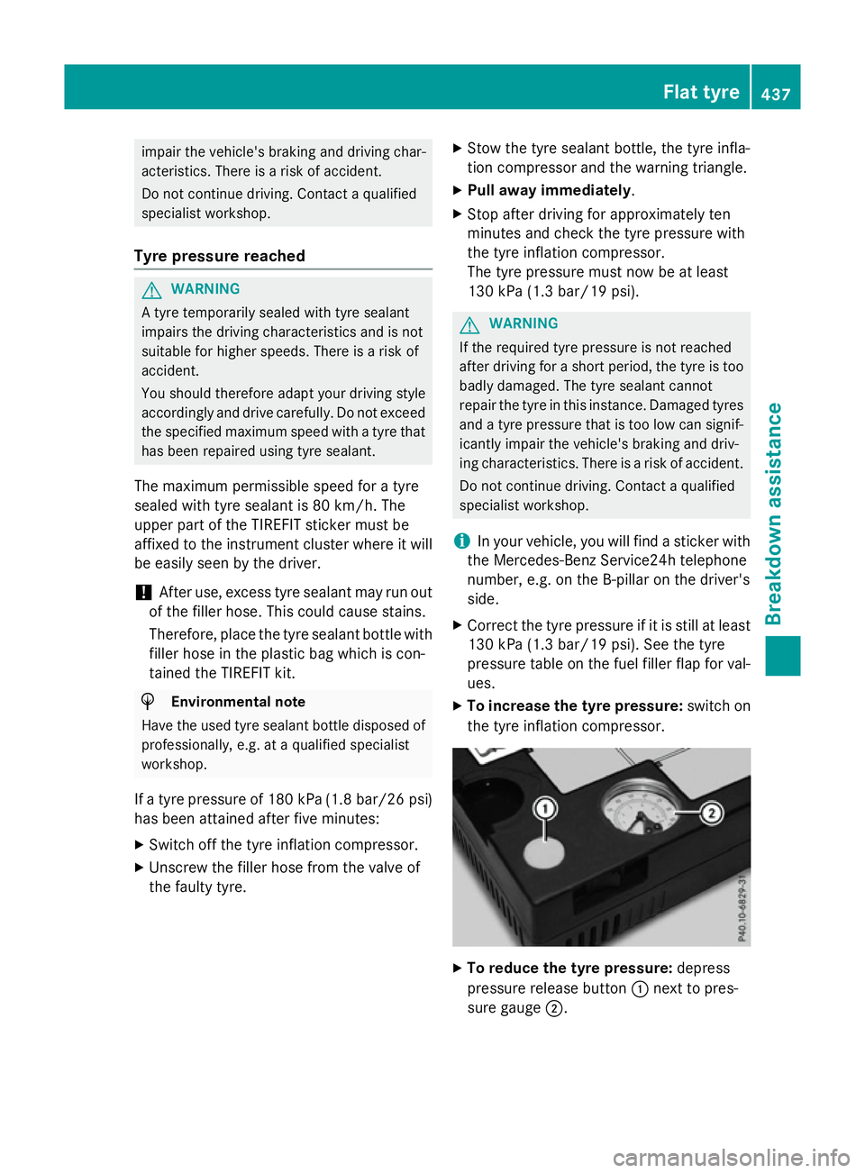
X To increase the tyre pressure: switch on
the tyre inflation compressor. X
To reduce the tyre pressure: depress
pressure release button :next to pres-
sure gauge ;. Flat tyre
437Breakdown assistance Z