2015 MERCEDES-BENZ G-CLASS SUV ignition
[x] Cancel search: ignitionPage 134 of 274
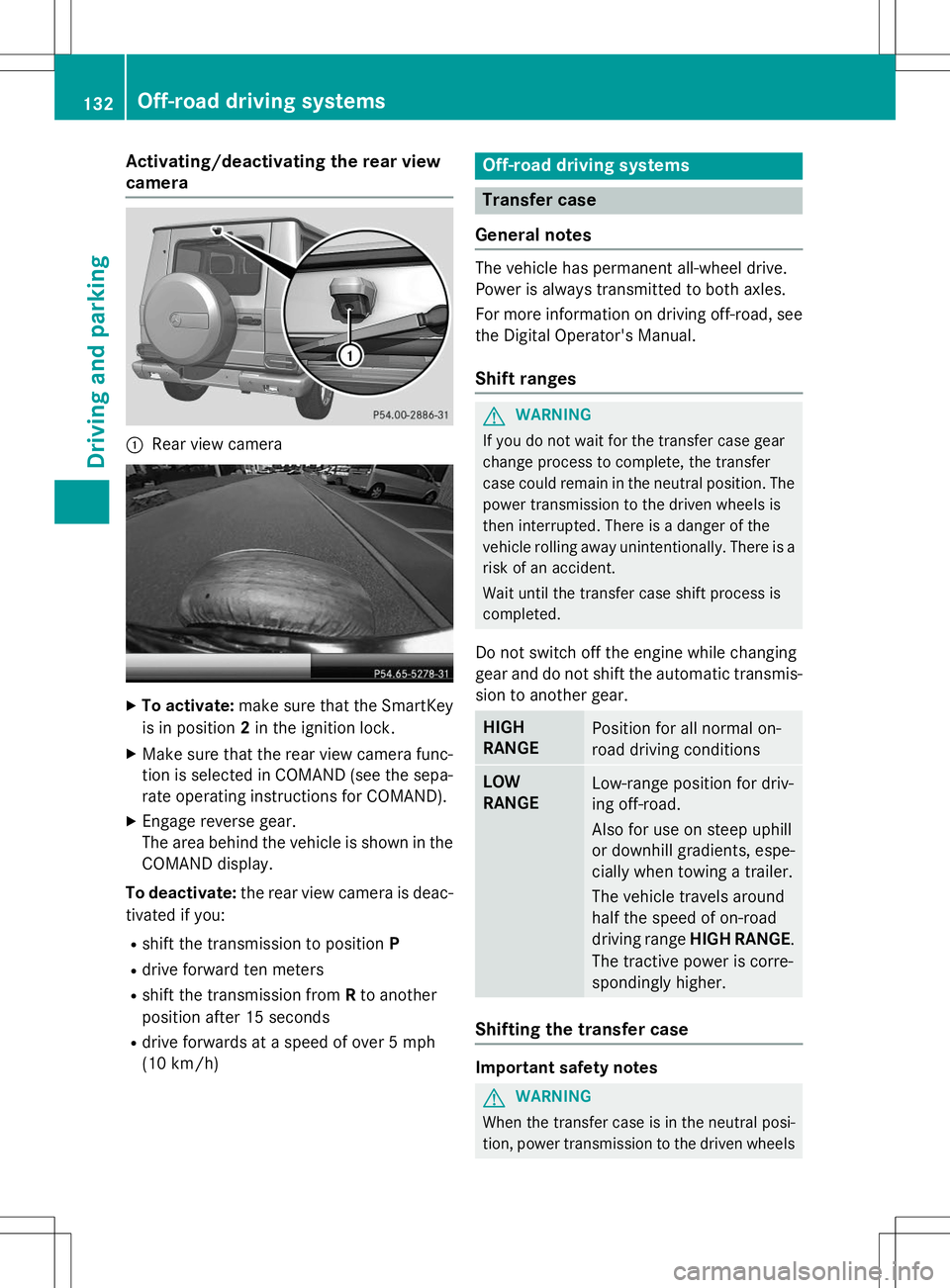
Activating/deactivating the rear view
camera
:Rear view camera
XTo activate: make sure that the SmartKey
is in position 2in the ignition lock.
X Make sure that the rear view camera func-
tion is selected in COMAND (see the sepa-
rate operating instructions for COMAND).
X Engage reverse gear.
The area behind the vehicle is shown in the
COMAND display.
To deactivate: the rear view camera is deac-
tivated if you:
R shift the transmission to position P
R drive forward ten meters
R shift the transmission from Rto another
position after 15 seconds
R drive forwards at a speed of over 5 mph
(10 km/h)
Off-road driving systems
Transfer case
General notes
The vehicle has permanent all-wheel drive.
Power is always transmitted to both axles.
For more information on driving off-road, see the Digital Operator's Manual.
Shift ranges
GWARNING
If you do not wait for the transfer case gear
change process to complete, the transfer
case could remain in the neutral position. The power transmission to the driven wheels is
then interrupted. There is a danger of the
vehicle rolling away unintentionally. There is a
risk of an accident.
Wait until the transfer case shift process is
completed.
Do not switch off the engine while changing
gear and do not shift the automatic transmis-
sion to another gear.
HIGH
RANGEPosition for all normal on-
road driving conditions
LOW
RANGELow-range position for driv-
ing off-road.
Also for use on steep uphill
or downhill gradients, espe-
cially when towing a trailer.
The vehicle travels around
half the speed of on-road
driving range HIGH RANGE .
The tractive power is corre-
spondingly higher.
Shifting the transfer case
Important safety notes
GWARNING
When the transfer case is in the neutral posi-
tion, power transmission to the driven wheels
132Off-road driving systems
Driving and pa rking
Page 136 of 274

positionNappears in the multifunction dis-
play.
R
TC Shift Canceled
The transfer case has not performed the
gear change process.
X Carry out the gear change process again.
Make sure to meet all conditions for chang-
ing gears.
R
TC Malfunction Visit Workshop
There is a malfunction in the transfer case.
X Do not shift the transfer case.
X Have the vehicle checked as soon as pos-
sible at a qualified specialist workshop.
Shifting to neutral
GWARNING
When the transfer case is in the neutral posi-
tion, power transmission to the driven wheels
is interrupted. As a result, the vehicle could
roll away. There is a risk of an accident.
Secure the vehicle with the parking brake, and on uphill or downhill gradients, also secure it
with a device such as a wheel chock.
X Turn the SmartKey to position 2in the igni-
tion lock ( Ypage 103).
X Apply the parking brake.
X Depress the brake pedal.
X Move the selector lever to position N
( Y page 106).
X Press and hold LOW RANGE button ;for
approximately ten seconds.
When the shift procedure is complete, the
TC neutral onmessage appears in the
multifunction display for five seconds.
If the gear change is not completed, the fol-
lowing messages could appear in the display( Y page 148).
iIf the transfer case is in neutral, the
SmartKey is in the ignition lock and you
open the driver's door, the
TCInNeutral
message appears in the multifunction dis-
play. If you then release the parking brake, a warning tone will sound.
Differential locks
General notes
GWARNING
When the differential locks are engaged, ABS, 4ETS, ESP ®
and BAS are deactivated. As a
result, the wheels could lock when braking
and the braking distance is increased. There is
a risk of an accident.
Disengage the differential locks immediately
on firm surfaces with good grip.
!In order to avoid damage to the transfer
case, you must operate the vehicle on a
dynamometer (1-axle dynamometer) onlyif:
R the axle not driven on is jacked up or
R the corresponding propeller shaft is dis-
connected and the transfer case differ-
ential lock is engaged.
Otherwise, the transfer case can be dam-aged.
Differential locks improve the traction of the vehicle.
Your vehicle is equipped with a differential
lock each for: R the transfer case: this controls the balance
between the front and rear axles.
R the rear axle: this controls the balance
between the wheels on the rear axle.
R the front axle: this controls the balance
between the wheels on the front axle.
Information on differential gear system
and differential lock
When the vehicle drives around a curve, the
wheels on the outside of the curve must cover
a greater distance. Therefore, the wheels turn more rapidly than on the inside. The differen-
tial, a gear system in the drive train, allows for
differing rotational speeds and facilitates cor- nering.
134Off-road driving systems
Driving and parking
Page 149 of 274

?Left control panel
ABack button
X To activate the on-board computer: turn
the SmartKey to position 1(Y page 103) in
the ignition lock.
You can control the multifunction display and
the settings in the on-board computer using
the buttons on the multifunction steering
wheel.
Left control panel
= ;R Calls up the menu and menu bar
9 :Press briefly:
R Scrolls in lists
R Selects a submenu or function
R In the
Audiomenu: selects a
stored station, an audio track or
a video scene
R In the
Tel(telephone) menu:
switches to the phone book and
selects a name or telephonenumber
9 :Press and hold:
R In the
Audiomenu: selects the
previous/next station or selects
an audio track or a video scene
using rapid scrolling
R In the
Tel(telephone) menu:
starts rapid scrolling if the phone
book is open
aR Confirms a selection/display
message
R In the
Tel(telephone) menu:
switches to the telephone book
and starts dialing the selectednumber
R In the
Audiomenu: stops the
station search function at the
desired station
Right control panel
~R Rejects or ends a call
R Exits phone book/redial mem- ory
6RMakes or accepts a call
R Switches to the redial memory
W XRAdjusts the volume
8RMute
Back button
%Press briefly:
R Back
R Switches off the Voice Control
System; see the separate oper-
ating instructions
R Hides display messages/calls
up the last
Tripmenu function
used
R Exits the telephone book/redial memory
%Press and hold:
R Calls up the standard display in the
Tripmenu
Menus and submenus
Menu overview
Press the =or; button on the steer-
ing wheel to call up the menu bar and select a
menu.
Operating the on-board computer ( Y page 146).
You can find more information on the individ-
ual menus in the Digital Operator's Manual.
Depending on the equipment installed in the
vehicle, you can call up the following menus:
R
Tripmenu
R
Navimenu (navigation instructions)
Menus and submenus147
On-board computer and displays
Z
Page 150 of 274
RAudioAudiomenu
R
TelTelmenu (telephone)
R
DriveAssistDriveAssistmenu (assistance)
R
ServServmenu
R
SettSettmenu (settings)
R
AMGAMGmenu in AMG vehicles
Display messages
Introduction
General notes
This section describes display messages rel-
evant to safety together with their solutions.
A description of other messages and their
solutions can be found in the Digital Opera-
tor's Manual.
Display messages appear in the multifunction
display.
Display messages with graphic displays may
be shown in simplified form in the Operator's Manual and may therefore differ from the
multifunction display.
Please respond in accordance with the dis-
play messages and follow the additional
notes in this Operator's Manual.
Certain display messages are accompanied
by an audible warning tone or a continuoustone.
When you stop and park the vehicle, please
observe the notes on parking ( Ypage 110).
Hiding display messages
X
Press the aor% button on the steer-
ing wheel to hide the display message.
The display message is cleared.
Display messages with a high priority are
shown in red.
You cannot hide display messages of the
highest priority. The multifunction display
shows these messages continuously until the
causes for the messages have been rem-edied.
Message memory menu
The on-board computer saves certain display
messages. You can call up the display mes-
sages in the message memory .
X Press the =or; button on the steer-
ing wheel to select the
Serv.Serv.menu.
If there are display messages, the multi-
function display shows
2 Messages2 Messages, for
example.
X Press the 9or: button to select the
entry, e.g.
2 Messages2 Messages.
X Press ato confirm.
X Press the 9or: button to scroll
through the display messages.
When the ignition is switched off, all display
messages are deleted, apart from some high-
priority display messages. Once the causes of the high-priority display messages have been
rectified, the corresponding display mes-
sages are also deleted.
148Display messages
On-board computer and displays
Page 200 of 274
phone network, a valid SIM card and a sub-scription to a security service.
R the battery is sufficiently charged.
R the corresponding mobile phone network is
available for transmitting data to the Cus-
tomer Center.
iDetermining the location of the vehicle on
a map is only possible if there is sufficient
GPS reception and the vehicle position can
be forwarded to the Customer Center.
The mbrace system
To adjust the volume during an mbrace call,
proceed as follows:
X Press the WorX button on the mul-
tifunction steering wheel.
or
X Use the COMAND volume control.
The mbrace system provides three different
services:
R Automatic and manual emergency call
R Roadside Assistance call
R MB Info call
USA only: you can find more information and
a description of all available features under
"Owners Online" at http://
www.mbusa.com .
System self-test
GWARNING
A malfunction in the system has been detec-
ted if one of the following conditions occurs:
R the indicator lamp in the SOS button does
not light up during the system self-diagno-sis.
R the indicator lamp in the ºRoadside
Assistance button does not light up during
the system self-diagnosis.
R the indicator lamp in the Einformation
button does not light up during the system
self-diagnosis.
R the indicator lamp in the SOS button, º
Roadside Assistance button or Einfor-
mation button continues to be lit red after
the system self-diagnosis.
R the
TeleAidinoperativeorTeleAid
not activatedmessage appears on the
multifunction display after the system self-
diagnosis.
If a malfunction is indicated as outlined above,
the system may not operate as expected. In
the event of an emergency, assistance must
be summoned by other means.
Have the system checked at the nearest
authorized Mercedes-Benz Center or contact
the following service hotlines:
R USA: Response Center at
1-888-990-9007
R Canada: Customer Service at
1-888-923-8367
After you have switched on the ignition, the
system carries out a self-diagnosis.
Emergency call
Important safety notes
GWARNING
If the indicator lamp in the SOS button is
flashing continuously and there was no voice
connection to the Response Center estab-
lished, then the mbrace system could not ini- tiate an emergency call (e.g. the relevant cel-
lular phone network is not available).
The message
Call Failedappears in the
multifunction display for approximately
10 seconds.
Should this occur, assistance must be sum-
moned by other means.
!You must have a license agreement to
activate the mbrace service. Ensure that
your system is activated and ready for use, and press the EMB Info call button to
register. If one of these steps is not carried
out, it may not be possible to activate thesystem.
198Features
Stowage and features
Page 206 of 274
Useful information
iThis Operator's Manual describes all
models and all standard and optional equip- ment of your vehicle available at the time of
publication of the Operator's Manual.
Country-specific differences are possible.
Please note that your vehicle may not be
equipped with all features described. This
also applies to safety-related systems and
functions.
iRead the information on qualified special-
ist workshops: ( Ypage 28).
Engine compartment
Hood
Important safety notes
GWARNING
If the hood is unlatched, it may open up when the vehicle is in motion and block your view.
There is a risk of an accident.
Never unlatch the hood while driving. Before
every trip, ensure that the hood is locked.
GWARNING
Certain components in the engine compart-
ment may be very hot, e.g. the drive system
and radiator. Working in the engine compart-
ment poses a risk of injury.
If possible, let the drive system cool down andonly touch the components described in the following.
GWARNING
Opening the hood when the engine is over-
heated or when there is a fire in the engine
compartment could expose you to hot gases
or other service products. There is a risk of
injury.
Let an overheated engine cool down before
opening the hood. If there is a fire in the
engine compartment, keep the hood closed
and contact the fire department.
GWARNING
The ignition system and the fuel injection sys-tem work under high voltage. If you touch
components which are under voltage, you
could get an electric shock. There is a risk of
injury.
Never touch components of the ignition sys-
tem or fuel injection system when the ignition is switched on.
GWARNING
The engine compartment contains moving
components. Certain components, such as
the radiator fan, may continue to run or start
again suddenly when the ignition is off. There is a risk of injury.
If you need to do any work inside the engine
compartment:
R switch off the ignition
R never reach into the area where there is a
risk of danger from moving components,
such as the fan rotation area
R remove jewelry and watches
R keep items of clothing and hair, for exam-
ple, away from moving parts
GWARNING
When the hood is open and the windshield
wipers are set in motion, you can be injured by
the wiper linkage. There is a risk of injury.
Always switch off the windshield wipers and
the ignition before opening the hood.
!Make sure that the windshield wipers are
not folded away from the windshield. You
could otherwise damage the windshield
wipers or the hood.
Do not touch the following when the ignition
is switched on: R ignition coils
R spark plug connectors
R test socket
204Engine compartment
Maintenance and care
Page 208 of 274
When checking the oil level:
R park the vehicle on a level surface.
R the engine should be switched off for
approximately five minutes if the engine is
at normal operating temperature.
R the engine should be switched off for at
least 30 minutes if the engine is not at
operating temperature, e.g. if you only start
the engine briefly.
X Pull oil dipstick :out of the dipstick guide
tube.
X Wipe off oil dipstick :.
X Slowly slide oil dipstick :into the guide
tube to the stop, and take it out again.
If the level is between MIN mark =and
MAX mark ;, the oil level is correct.
X Add oil if necessary.
Checking the oil level using the on-
board computer
!Do not add too much oil. adding too much
engine oil can result in damage to the
engine or to the catalytic converter. Have
excess engine oil siphoned off.
G 65 AMG: the oil level can be checked using
the on-board computer only.
On all other models, the oil dipstick must be
used to check the engine oil level.
When checking the oil level:
R park the vehicle on a level surface.
R the engine should be switched off for
approximately five minutes if the engine is
at normal operating temperature.
X Make sure that the SmartKey is in posi-tion 2in the ignition lock.
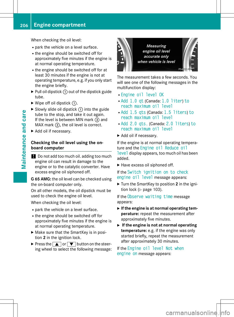
X Press the 9or: button on the steer-
ing wheel to select the following message:
The measurement takes a few seconds. You
will see one of the following messages in the multifunction display: R
Engine oil level OK
RAdd 1.0 qt(Canada:1.0 liter)to
reach maximum oil level
RAdd 1.5 qts(Canada:1.5 liters)to
reach maximum oil level
RAdd2.0 qts.(Canada:2.0 liters)to
reach maximum oil level
X Add oil if necessary.
If the engine is at normal operating tempera- ture and the
Engine oil Reduce oil
leveldisplay appears, too much oil has been
added.
X Have excess oil siphoned off.
If the
Switch ignition on to check
engine oil levelmessage appears:
X Turn the SmartKey to position 2in the igni-
tion lock ( Ypage 103).
If the
Observe waiting timemessage
appears:
X If the engine is at normal operating tem-
perature: repeat the measurement after
approximately five minutes.
X If the engine is not at normal operating
temperature: e.g. if the engine was only
started briefly, repeat the measurement
after approximately 30 minutes.
If the
Engine oil level Not when
engine onmessage appears:
206Engine compartment
Maintenance and care
Page 210 of 274

Additional service products
Checking coolant level
GWARNING
Certain components in the engine compart-
ment, such as the engine, radiator and parts
of the exhaust system, can become very hot.
Working in the engine compartment poses a
risk of injury.
Where possible, let the engine cool down and touch only the components described in the
following.
GWARNING
The engine cooling system is pressurized, par-ticularly when the engine is warm. When
opening the cap, you could be scalded by hotcoolant spraying out. There is a risk of injury.
Let the engine cool down before opening the
cap. Wear eye and hand protection when
opening the cap. Open the cap slowly half a
turn to allow pressure to escape.
X Park the vehicle on a level surface.
Only check the coolant level when the vehi-
cle is on a level surface and the engine has
cooled down.
X Turn the SmartKey to position 2
( Y page 103) in the ignition lock.
X Check the coolant temperature display in
the instrument cluster.
The coolant temperature must be below
158 ‡ (70 †). X
Slow ly turn cap :half a turn counter-
clockwise and allow excess pressure to
escape.
X Turn cap :further counter-clockwise and
remove it.
If the coolant is at the level of marker bar =
in the filler neck when cold, there is enough coolant in coolant expansion tank ;.
If the coolant level is approximately 0.6 in
(1.5 cm) above marker bar =in the filler
neck when warm, there is enough coolant
in coolant expansion tank ;.
X If necessary, add coolant that has been tes-
ted and approved by Mercedes-Benz.
X Replace cap :and turn it clockwise as far
as it will go.
For further information on coolant, see( Y page 264).
Adding washer fluid to the windshield
washer system/headlamp cleaning
system
GWARNING
Certain components in the engine compart-
ment, such as the engine, radiator and parts
of the exhaust system, can become very hot.
Working in the engine compartment poses a
risk of injury.
Where possible, let the engine cool down and
touch only the components described in the
following.
GWARNING
Windshield washer concentrate could ignite if it comes into contact with hot engine compo-
nents or the exhaust system. There is a risk of
fire and injury.
Make sure that no windshield washer con-
centrate is spilled next to the filler neck.
208Engine compartment
Maintenance and care