2015 MERCEDES-BENZ E-CLASS CABRIOLET ignition
[x] Cancel search: ignitionPage 231 of 349
X
Press the =or; button on the steering
wheel to select the Settings
Settings menu.
X Press the :or9 button to select the
Convenience
Convenience submenu.
X Press ato confirm.
X Press the :or9 button to select the
Auto. fold in
Auto. fold in function.
If the Auto.
Auto. fold
foldin
infunction is switched on,
the multifunction display shows the vehicle's
exterior mirror in orange.
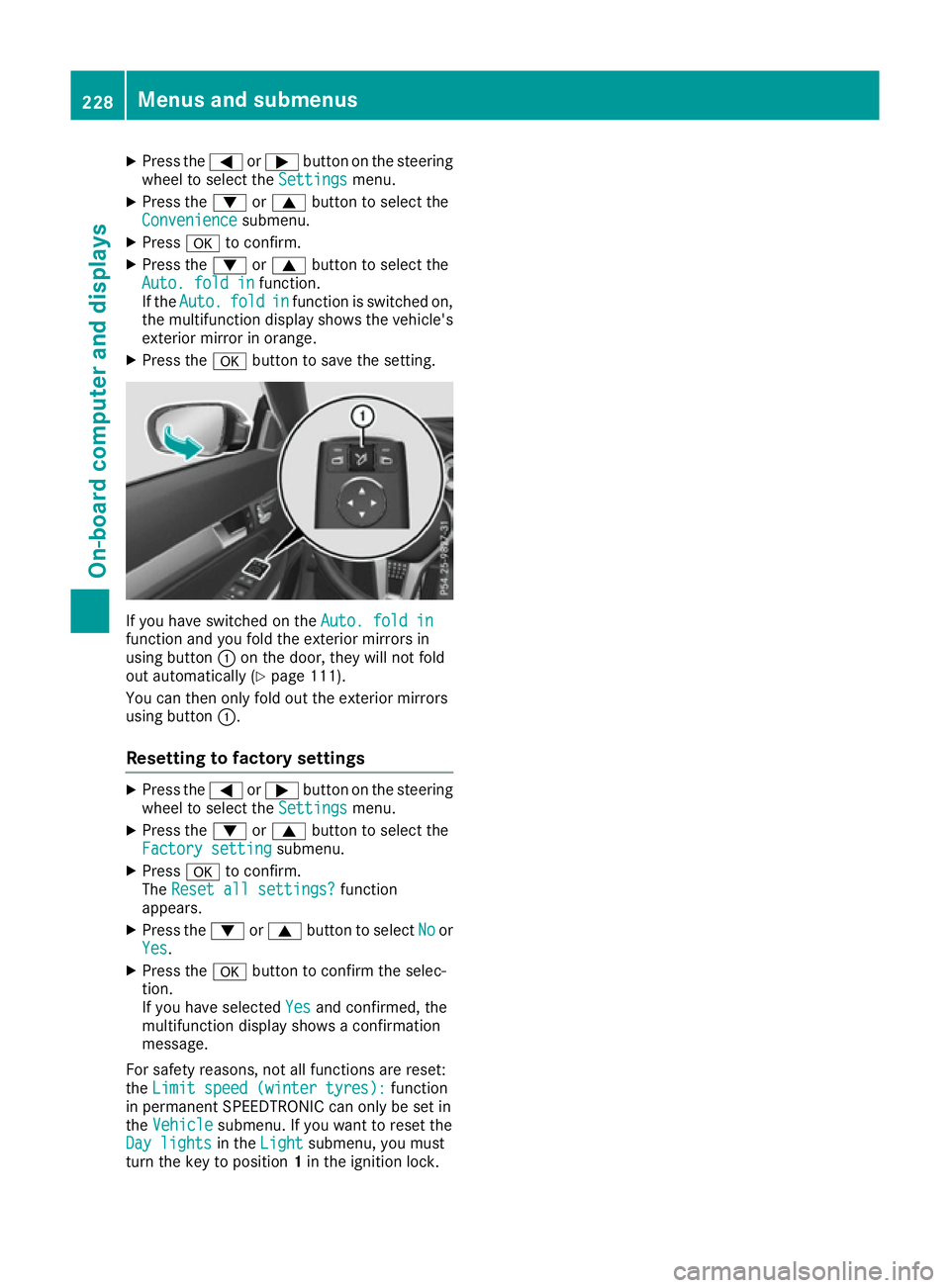
X Press the abutton to save the setting. If you have switched on the
Auto. fold in
Auto. fold in
function and you fold the exterior mirrors in
using button :on the door, they will not fold
out automatically (Y page 111).
You can then only fold out the exterior mirrors
using button :.
Resetting to factory settings X
Press the =or; button on the steering
wheel to select the Settings
Settingsmenu.
X Press the :or9 button to select the
Factory setting
Factory setting submenu.
X Press ato confirm.
The Reset all settings?
Reset all settings? function
appears.
X Press the :or9 button to select No
Noor
Yes
Yes.
X Press the abutton to confirm the selec-
tion.
If you have selected Yes Yesand confirmed, the
multifunction display shows a confirmation
message.
For safety reasons, not all functions are reset:
the Limit speed (winter tyres):
Limit speed (winter tyres): function
in permanent SPEEDTRONIC can only be set in
the Vehicle
Vehicle submenu. If you want to reset the
Day lights
Day lights in theLight
Light submenu, you must
turn the key to position 1in the ignition lock. 228
Menus and submenusOn-board computer and displays
Page 232 of 349
Display messages
Introduction
General notes Display messages appear in the multifunction display.
Display messages with graphic symbols are simplified in the Owner's Manual and may differ from
the symbols in the multifunction display.
Please respond in accordance with the display messages and follow the additional notes in this
Owner's Manual.
Certain display messages are accompanied by an audible warning tone or a continuous tone.
When the ignition is switched off, all display messages are deleted apart from some high-priority
display messages. Once the causes of the high-priority display messages have been rectified, the
corresponding display messages are also deleted.
When you stop and park the vehicle, please observe the notes on:
R HOLD function (Y page 177)
R Parking (Y page 157)
Hiding display messages X
Press the aor% button on the steering wheel.
The multifunction display hides the display message.
The multifunction display shows high-priority display messages in red. Some high-priority display
messages cannot be hidden.
The multifunction display shows these messages continuously until the causes for the messages
have been remedied.
Message memory The on-board computer saves certain display messages in the
message memory. You can call up
the display messages:
X Press the =or; button on the steering wheel to select the Service
Service menu.
If there are display messages, the multifunction display shows 2 messages
2 messages, for example.
X Press the 9or: button to select the entry, e.g. 2 messages
2 messages.
X Press ato confirm.
X Press the 9or: button to scroll through the display messages. Display
messages
229On-board computer and displays Z
Page 255 of 349
Display messages
Possible causes/consequences and
M
MSolutions J
Close Close
boot
bootseparator
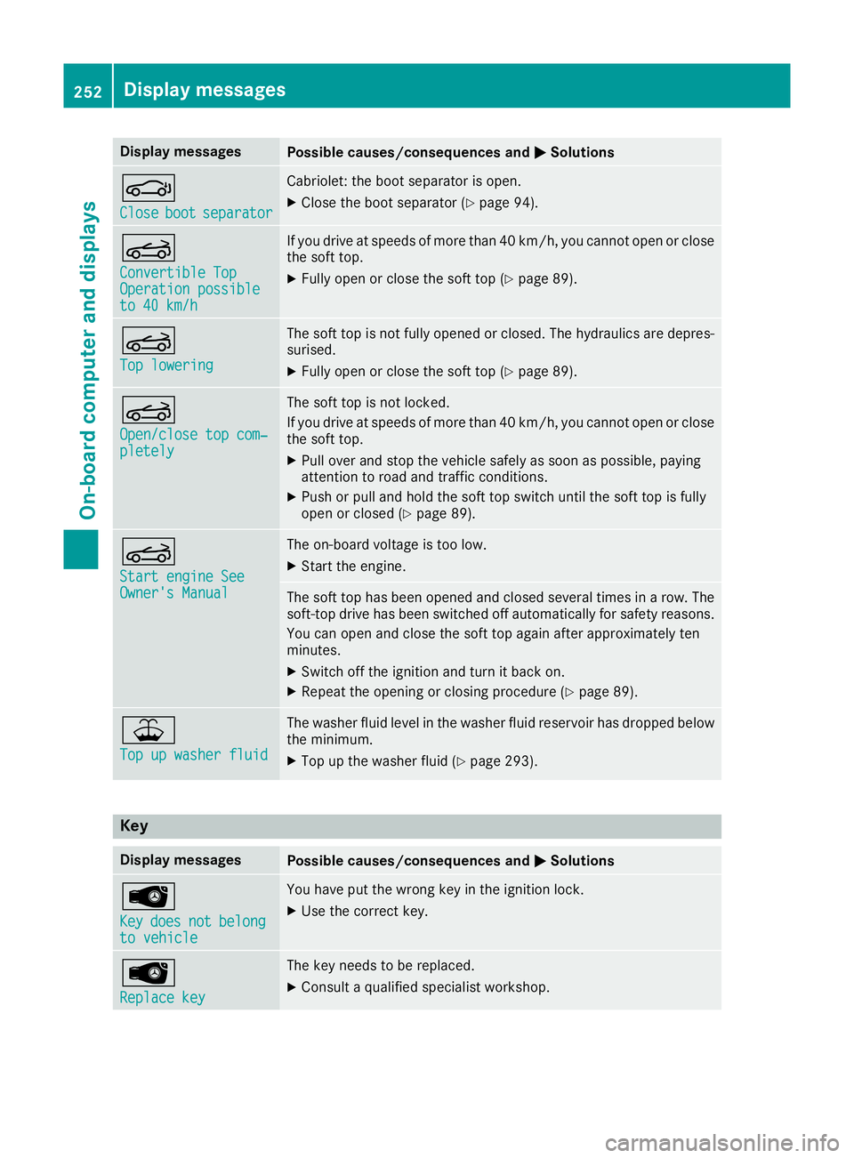
separator Cabriolet: the boot separator is open.
X Close the boot separator (Y page 94).K
Convertible Top Convertible Top
Operation possible Operation possible
to 40 km/h to 40 km/h If you drive at speeds of more than 40 km/h, you cannot open or close
the soft top.
X Fully open or close the soft top (Y page 89).K
Top lowering Top lowering The soft top is not fully opened or closed. The hydraulics are depres-
surised.
X Fully open or close the soft top (Y page 89).K
Open/close top com‐ Open/close top com‐
pletely pletely The soft top is not locked.
If you drive at speeds of more than 40 km/h, you cannot open or close
the soft top.
X Pull over and stop the vehicle safely as soon as possible, paying
attention to road and traffic conditions.
X Push or pull and hold the soft top switch until the soft top is fully
open or closed (Y page 89). K
Start engine See Start engine See
Owner's Manual Owner's Manual The on-board voltage is too low.
X Start the engine. The soft top has been opened and closed several times in a row. The
soft-top drive has been switched off automatically for safety reasons.
You can open and close the soft top again after approximately ten
minutes.
X Switch off the ignition and turn it back on.
X Repeat the opening or closing procedure (Y page 89).¥
Top up washer fluid Top up washer fluid The washer fluid level in the washer fluid reservoir has dropped below
the minimum.
X Top up the washer fluid (Y page 293).Key
Display messages
Possible causes/consequences and
M
MSolutions Â
Key Key
does
does not
notbelong
belong
to vehicle
to vehicle You have put the wrong key in the ignition lock.
X Use the correct key. Â
Replace key Replace key The key needs to be replaced.
X Consult a qualified specialist workshop. 252
Display
messagesOn-board computer and displays
Page 256 of 349
Display messages
Possible causes/consequences and
M
MSolutions Â
Change Change
key
keybatteries
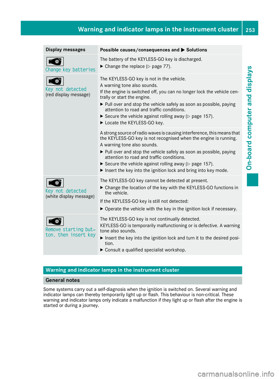
batteries The battery of the KEYLESS-GO key is discharged.
X Change the replace (Y page 77).Â
Key not detected Key not detected
(red display message) The KEYLESS-GO key is not in the vehicle.
A warning tone also sounds.
If the engine is switched off, you can no longer lock the vehicle cen-
trally or start the engine.
X Pull over and stop the vehicle safely as soon as possible, paying
attention to road and traffic conditions.
X Secure the vehicle against rolling away (Y page 157).
X Locate the KEYLESS-GO key. A strong source of radio waves is causing interference, this means that
the KEYLESS-GO key is not recognised when the engine is running.
A warning tone also sounds.
X Pull over and stop the vehicle safely as soon as possible, paying
attention to road and traffic conditions.
X Secure the vehicle against rolling away (Y page 157).
X Insert the key into the ignition lock and bring into key mode. Â
Key not detected Key not detected
(white display message) The KEYLESS-GO key cannot be detected at present.
X Change the location of the key with the KEYLESS-GO functions in
the vehicle.
If the KEYLESS-GO key is still not detected: X Operate the vehicle with the key in the ignition lock if necessary. Â
Remove Remove
starting
starting but‐
but‐
ton,
ton, then
theninsert
insert key
key The KEYLESS-GO key is not continually detected.
KEYLESS-GO is temporarily malfunctioning or is defective. A warning tone also sounds.
X Insert the key into the ignition lock and turn it to the desired posi-
tion.
X Consult a qualified specialist workshop. Warning and indicator lamps in the instrument cluster
General notes
Some systems carry out a self-diagnosis when the ignition is switched on. Several warning and
indicator lamps can thereby temporarily light up or flash. This behaviour is non-critical. These
warning and indicator lamps only indicate a malfunction if they light up or flash after the engine is started or during a journey. Wa
rning and indi cator lamps in the instrument cluster
253On-board computer and displays Z
Page 262 of 349

Engine
Warning/
indicator
lamp
N N
Signal type
Possible causes/consequences and M
MSolutions ;
N
The yellow engine diagnostics warning lamp lights up while the engine is run-
ning.
There may be a fault, for example:
R in the engine management
R in the fuel injection system
R in the exhaust system
R in the ignition system (for vehicles with petrol engines)
R in the fuel system
The emission limit values may be exceeded and the engine may be running in
emergency mode.
X Consult a qualified specialist workshop immediately.
Vehicles with a diesel engine: the fuel tank has been run dry (Y page 157).
X After refuelling start the engine three to four times.
If the yellow engine diagnostics warning lamp goes out, emergency running
mode is cancelled. You do not need to have the vehicle checked. 8
N
The yellow reserve fuel warning lamp is on while the engine is running.
The fuel level has dropped into the reserve range.
Operation of the auxiliary heating is deactivated if the fuel level drops into the
reserve range.
X Refuel at the nearest filling station. ?
N
The red coolant warning lamp lights up while the engine is running and the
coolant temperature gauge is at the start of the scale.
The temperature sensor for the coolant temperature gauge is faulty.
The coolant temperature is no longer being monitored. There is a risk of engine
damage if the coolant temperature is too high.
X Stop the vehicle immediately, paying attention to road and traffic conditions,
and switch off the engine. Do not continue driving under any circumstances.
X Safeguard the vehicle against rolling away (Y page 157).
X Consult a qualified specialist workshop. Warning and indicator lamps in the instrument cluster
259On-board computer and displays Z
Page 283 of 349
X
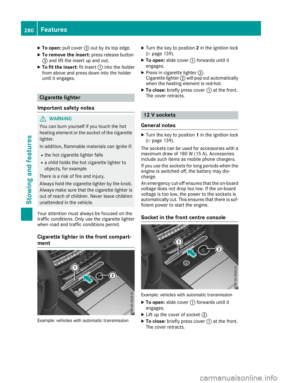
To open: pull cover ;out by its top edge.
X To remove the insert: press release button
= and lift the insert up and out.
X To fit the insert: fit insert:into the holder
from above and press down into the holder
until it engages. Cigarette lighter
Important safety notes G
WARNING
You can burn yourself if you touch the hot
heating element or the socket of the cigarette lighter.
In addition, flammable materials can ignite if:
R the hot cigarette lighter falls
R a child holds the hot cigarette lighter to
objects, for example
There is a risk of fire and injury.
Always hold the cigarette lighter by the knob.
Always make sure that the cigarette lighter is
out of reach of children. Never leave children unattended in the vehicle.
Your attention must always be focused on the
traffic conditions. Only use the cigarette lighter when road and traffic conditions permit.
Cigarette lighter in the front compart-
ment Example: vehicles with automatic transmission X
Turn the key to position 2in the ignition lock
(Y page 139).
X To open: slide cover :forwards until it
engages.
X Press in cigarette lighter ;.
Cigarette lighter ;will pop out automatically
when the heating element is red-hot.
X To close: briefly press cover :at the front.
The cover retracts. 12 V sockets
General notes X
Turn the key to position 1in the ignition lock
(Y page 139).
The sockets can be used for accessories with a
maximum draw of 180 W(15 A). Accessories
include such items as mobile phone chargers.
If you use the sockets for long periods when the engine is switched off, the battery may dis-
charge.
An emergency cut-off ensures that the on-boardvoltage does not drop too low. If the on-board
voltage is too low, the power to the sockets is
automatically cut. This ensures that there is suf-
ficient power to start the engine.
Socket in the front centre console Example: vehicles with automatic transmission
X To open: slide cover :forwards until it
engages.
X Lift up the cover of socket ;.
X To close: briefly press cover :at the front.
The cover retracts. 280
FeaturesStowing and fea
tures
Page 285 of 349
An exterior aerial has the following advantages:
R it conducts the electromagnetic fields gener-
ated by a wireless device to the exterior
R the field strength in the vehicle interior is
lower than in a vehicle that does not have an exterior aerial
Information on retrofitting two-way radios and
mobile phones (RF transmitters) (Y page 335).
General notes There are various mobile phone brackets that
may be fitted in your vehicle; in some cases,
these are country-specific.
More information on suitable mobile phones,
mobile phone brackets and on connecting Blue-
tooth ®
-capable mobile phones with the multi-
media system can be obtained:
R at your Mercedes-Benz Service Centre
R on the Internet at http://www.mercedes-
benz.com/connect
The functions and services available when you
use the phone depend on your mobile phone
model and service provider.
Using a mobile phone To connect a mobile phone to the exterior aerial
and charge it, insert it into the mobile phone
bracket.
X Open the telephone compartment
(Y page 274).
X Place the mobile phone bracket into the pre-
installed fitting; see the separate installation
instructions for the mobile phone fitting.
X Insert the mobile phone into the mobile phone
bracket; see the separate installation instruc-
tions for the mobile phone fitting.
i The mobile phone can also be operated
without being in the bracket. However, the
charging function and aerial function are not
available.
In order to use Bluetooth ®
(SAP profile) on your
telephone module, you must first insert the tele-
phone module into the pre-installed fitting. This connects it to the exterior aerial. If you wish to
charge the mobile phone, then you must con-
nect it to a USB port.
Further information on the telephone module
with Bluetooth ®
(SAP profile) can be found in the
Digital Owner's Manual. Operating the mobile phone You can operate the telephone using the
6
and ~ buttons on the multifunction steering
wheel. You can operate other mobile phone
functions via the on-board computer
(Y page 219).
When you remove the key from the ignition lock,
the mobile phone is disconnected from the
hands-free system. Active calls will first be
transferred to the mobile phone directly.
Mobile phone bracket in the stowage
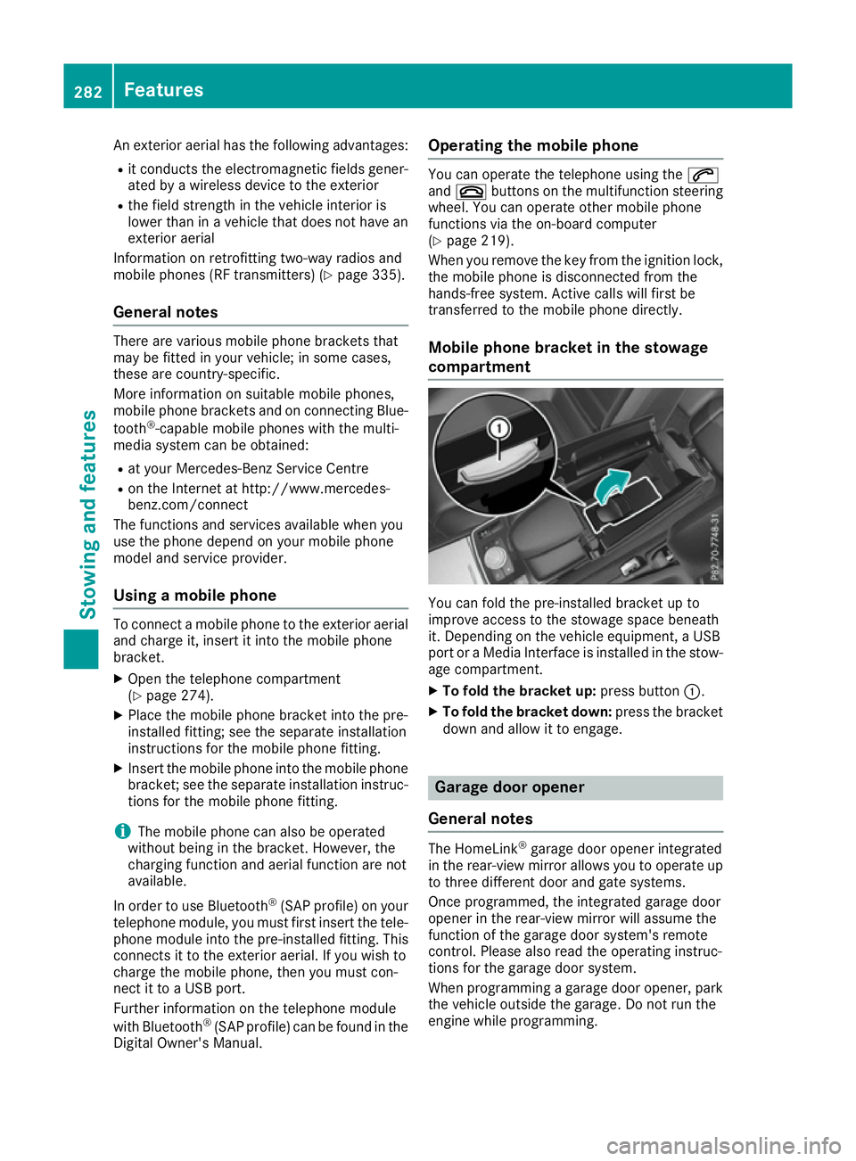
compartment You can fold the pre-installed bracket up to
improve access to the stowage space beneath
it. Depending on the vehicle equipment, a USB
port or a Media Interface is installed in the stow- age compartment.
X To fold the bracket up: press button:.
X To fold the bracket down: press the bracket
down and allow it to engage. Garage door opener
General notes The HomeLink
®
garage door opener integrated
in the rear-view mirror allows you to operate up
to three different door and gate systems.
Once programmed, the integrated garage door
opener in the rear-view mirror will assume the
function of the garage door system's remote
control. Please also read the operating instruc-
tions for the garage door system.
When programming a garage door opener, park
the vehicle outside the garage. Do not run the
engine while programming. 282
FeaturesSto
wing an d features
Page 286 of 349
The garage door opener is only available for cer-
tain countries. Observe the legal requirements
for each individual country.
The HomeLink ®
garage door opener is compat-
ible with most European garage and gate opener
drives. More information on HomeLink ®
and/or
compatible products is available:
R at a qualified specialist workshop
R via the HomeLink ®
Hotline
(0) 08000 466 354 65 or alternatively
+49 (0) 6838 907-277
R on the Internet at http://www.homelink.com
Important safety notes G
WARNING
When you operate or program the garage door with the integrated garage door opener, per-
sons in the range of movement of the garage
door can become trapped or struck by the
garage door. There is a risk of injury.
When using the integrated garage door
opener, always make sure that nobody is
within the range of movement of the garage
door. G
WARNING
Combustion engines emit poisonous exhaust
gases such as carbon monoxide. Inhaling
these exhaust gases leads to poisoning. There is a risk of fatal injury. Therefore never leave
the engine running in enclosed spaces with-
out sufficient ventilation.
Programming Programming buttons
Pay attention to the "Important safety notes"
(Y page 283). Garage door remote control
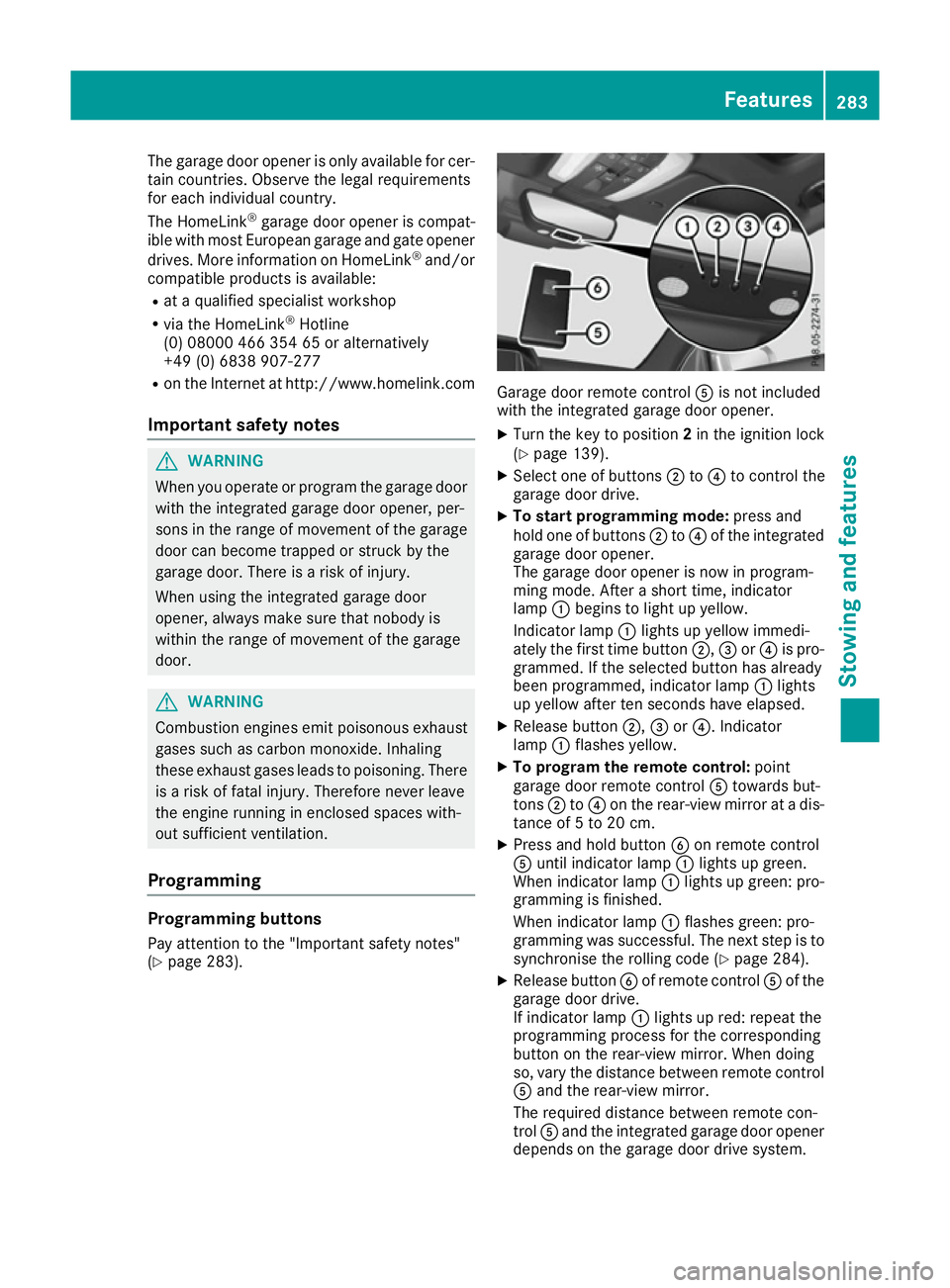
Ais not included
with the integrated garage door opener.
X Turn the key to position 2in the ignition lock
(Y page 139).
X Select one of buttons ;to? to control the
garage door drive.
X To start programming mode: press and
hold one of buttons ;to? of the integrated
garage door opener.
The garage door opener is now in program-
ming mode. After a short time, indicator
lamp :begins to light up yellow.
Indicator lamp :lights up yellow immedi-
ately the first time button ;,=or? is pro-
grammed. If the selected button has already
been programmed, indicator lamp :lights
up yellow after ten seconds have elapsed.
X Release button ;,=or?. Indicator
lamp :flashes yellow.
X To program the remote control: point
garage door remote control Atowards but-
tons ;to? on the rear-view mirror at a dis-
tance of 5 to 20 cm.
X Press and hold button Bon remote control
A until indicator lamp :lights up green.
When indicator lamp :lights up green: pro-
gramming is finished.
When indicator lamp :flashes green: pro-
gramming was successful. The next step is to
synchronise the rolling code (Y page 284).
X Release button Bof remote control Aof the
garage door drive.
If indicator lamp :lights up red: repeat the
programming process for the corresponding
button on the rear-view mirror. When doing
so, vary the distance between remote control A and the rear-view mirror.
The required distance between remote con-
trol Aand the integrated garage door opener
depends on the garage door drive system. Features
283Stowing and features Z