2015 MERCEDES-BENZ CLA SHOOTING BRAKE flat tire
[x] Cancel search: flat tirePage 14 of 421
Anti-dazzle mode (automatic) ........ 120
Folding in when locking (on-board
computer) ...................................... 261
Folding in/out (automatically) ....... 120
Folding in/out (electrically )........... 120
Out of position (troubleshooting) ... 120
Parking position ............................. 121
Resetting ....................................... 120
Storing settings (memory func-
tion) ............................................... 122 F
Fault message see Display messages
Filler cap
see Fuel filler flap
Fire extinguisher ............................... 351
First-aid kit ......................................... 350
Fitting a wheel
Fitting a wheel ............................... 383
Lowering the vehicle ...................... 383
Preparing the vehicle ..................... 380
Raising the vehicle ......................... 381
Removing a wheel .......................... 383
Securing the vehicle against roll-
ing away ........................................ 381
Flat tyre
Changing a wheel/fitting the
spare wheel ................................... 379
MOExtended tyre s......................... 352
Preparing the vehicle ..................... 352
TIREFIT kit ...................................... 353
see Emergency spare wheel
Floormat ............................................. 331
Foglamps
Switching on/of f........................... 127
Foglamps (extended range) .............. 131
Frequencies
Mobile phone ................................. 400
Two-way radio ................................ 400
Front foglamps
Display message ............................ 281
Front-passenger front airbag deac-
tivation
Display message ............................ 278 Front-passenger front airbag deac-
tivation system
Operation ......................................... 52
Problems ......................................... 56
System self-test ............................... 54
Fuel
Additives ........................................ 405
Consumption information .............. 406
Consumption statistics .................. 250
Displaying the current consump-
tion ................................................ 250
Displaying the range ...................... 250
Driving tip s.................................... 196
E10 ................................................ 404
Fuel gaug e....................................... 32
Grade (petrol) ................................ 404
Important safety notes .................. 403
Low outside temperatures ............. 406
Notes for CLA 250 ......................... 405
Notes for Mercedes‑ AMG vehi-
cles ................................................ 404
Problem (malfunction) ................... 191
Quality (diesel )............................... 405
Refuelling ....................................... 188
Tank content/reserve fue l............. 403
Fuel filler flap
Opening ......................................... 189
Fuel filter (white display message) .. 286
Fuel level
Calling up the range (on-board
computer) ...................................... 250
Gauge .............................................. 32
Fuel reserve
see Fuel
Fuel tank
Capacity ........................................ 403
Problem (malfunction) ................... 191
Fuses
Allocation chart ............................. 368
Before changing ............................. 367
Fuse box in the engine compart-
ment .............................................. 367
Fuse box in the front-passenger
footwell .......................................... 368
Important safety notes .................. 367 Index
11
Page 23 of 421
see Manual transmission
Transmission position display
(DIRECT SELECT lever) ......................178
Transporting the vehicle .................. 365
Trim pieces (cleaning instruc-
tions) ................................................. .346
Trip computer (on-board com-
puter) ................................................. .250
Trip meter
Calling up ....................................... 250
Resetting (on-board computer) ...... 251
Turn signals
Changing bulbs (front) ................... 136
Changing bulbs (rear) .................... 137
Switching on/off ........................... 129
Two-way radio
Frequencies ................................... 400
Installation ..................................... 400
Transmission output (maximum) .... 400
Type identification plate
see Vehicle identification plate
Tyre pressure
Calling up (on-board computer) ..... 376
Display message ............................ 292
Not reached (TIREFIT) .................... 355
Reached (TIREFIT) .......................... 355
Recommended ............................... 374
Tyre pressure loss warning
General notes ................................ 375
Important safety notes .................. 375
Restarting ...................................... 376
Tyre pressure monitor
Checking the tyre pressure elec-
tronically ........................................ 377
Function/notes ............................ .376
General notes ................................ 376
Important safety notes .................. 376
Radio type approval for the tyre
pressure monitor ........................... 379
Restarting ...................................... 378
Warning lamp ................................. 313
Warning message .......................... 378
Tyres
Changing a wheel .......................... 379
Checking ........................................ 371
Direction of rotatio n...................... 380
Display message ............................ 292
General notes ................................ 384 Important safety notes .................. 370
Information on driving .................... 370
M+S tyres ...................................... 372
MOExtended tyre
s......................... 372
Replacing ....................................... 379
Service life ..................................... 371
Storing ........................................... 380
Summer tyres ................................ 372
Tyre size (data ).............................. 384
Tyre tread ...................................... 371
Wheel and tyre combinations ........ 386
see Flat tyre U
Unlocking Emergency unlocking ....................... 95
From inside the vehicle (central
unlocking button) ............................. 94
Upshift indicator (on-board com-
puter, Mercedes-AMG vehicles) ....... 262 V
Vanity mirror (in sun visor) .............. 327
Variable SPEEDTRONIC
see SPEEDTRONIC
Vehicle
Correct use ...................................... 25
Data acquisition ............................... 26
Display message ............................ 294
Electronics ..................................... 400
Equipment ....................................... 23
Implied warranty .............................. 25
Individual settings .......................... 258
Leaving parked up ......................... 195
Locking (in an emergency) ............... 96
Locking (key) ................................... 87
Lowering ........................................ 383
Pulling away ................................... 168
Raising ........................................... 381
Registration ..................................... 25
Securing from rolling away ............ 381
Transporting .................................. 365
Unlocking (in an emergency) ........... 95
Unlocking (key) ................................ 87
Vehicle data ................................... 410
Vehicle data
Boot load (maximum) ..................... 410 20
Index
Page 68 of 421

lamp is lit continuously (Y
page 43)is the
front-passenger front airbag disabled.
Always observe the information on suitable
positioning of the child restraint system
(Y page 65) in addition to the child restraint
system manufacturer's installation and oper-
ating instructions.
Forward-facing child restraint system If it is absolutely necessary to fit a forward-
facing child restraint system to the front-
passenger seat, always move the front-
passenger seat as far back as possible. Fully
retract the seat cushion length. The entire
base of the child restraint system must
always rest on the seat cushion of the front-
passenger seat. The backrest of the child
restraint system must, as far as possible, lie
flat against the backrest of the front-
passenger seat. The child restraint system
must not touch the roof or be put under strain
by the head restraint. Adjust the angle of the seat backrest and the head restraint position accordingly. Always make sure that the shoul-
der belt strap is correctly routed from the
vehicle belt outlet to the shoulder belt guide
on the child restraint system. The shoulder
belt strap must be routed forwards and down- wards from the vehicle belt outlet. If neces-
sary, adjust the vehicle belt outlet and the
front-passenger seat accordingly.
Always observe the information on suitable
positioning of the child restraint system
(Y page 65) in addition to the child restraint
system manufacturer's installation and oper-
ating instructions. Suitable positioning of the child
restraint system
Introduction Only child restraint systems approved in
accordance with the ECE standards ECE R44
or ECE R129 (i-Size child restraint systems)
are permitted for use in the vehicle. For certain child restraint systems in weight
categories II or III, this can mean that the area
of use is restricted. The maximum size setting of the child restraint system is not possible
due to possible contact with the roof.
"Universal" category child restraint systems
can be recognised by their orange approval
label and the text "Universal" or an "i-Size"
label. Example: approval labels on the child
restraint system
ISOFIX or i-Size child restraint systems of the
“Universal“ category can be used on seats
labelled U, UF, IUF or i-U in accordance with
the following tables:
R Suitability of the seats for attaching belt-
secured child restraint systems
R Suitability of the seats for attaching ISOFIX
child restraint systems
R Suitability of the seats for attaching an i-
Size child restraint system.
Semi-universal child restraint systems are
indicated by the text "semi-universal" on the
approval label. These can be used if the vehi- Children in the vehicle
65Safety Z
Page 354 of 421
Fire extinguisher
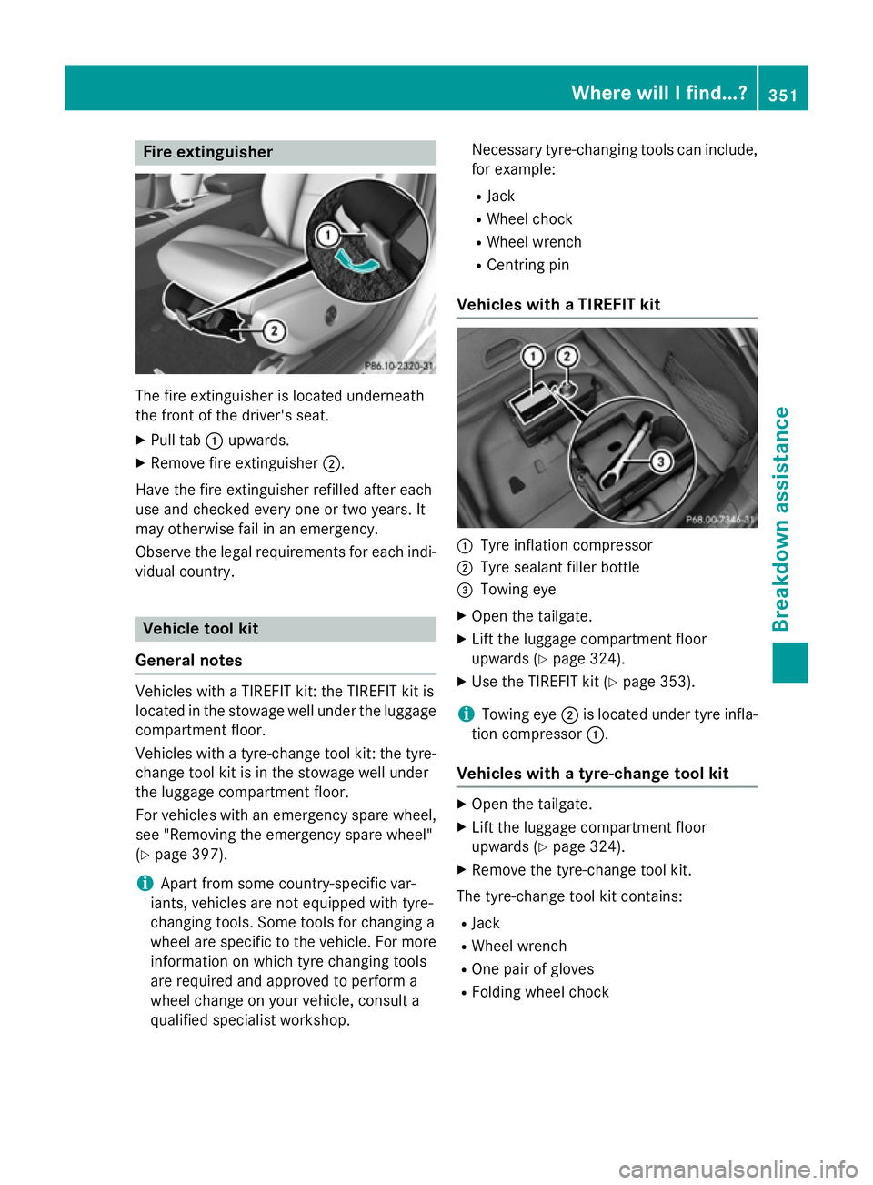
The fire extinguisher is located underneath
the front of the driver's seat.
X Pull tab :upwards.
X Remove fire extinguisher ;.
Have the fire extinguisher refilled after each
use and checked every one or two years. It
may otherwise fail in an emergency.
Observe the legal requirements for each indi- vidual country. Vehicle tool kit
General notes Vehicles with a TIREFIT kit: the TIREFIT kit is
located in the stowage well under the luggage
compartment floor.
Vehicles with a tyre-change tool kit: the tyre-change tool kit is in the stowage well under
the luggage compartment floor.
For vehicles with an emergency spare wheel, see "Removing the emergency spare wheel"
(Y page 397).
i Apart from some country-specific var-
iants, vehicles are not equipped with tyre-
changing tools. Some tools for changing a
wheel are specific to the vehicle. For more information on which tyre changing tools
are required and approved to perform a
wheel change on your vehicle, consult a
qualified specialist workshop. Necessary tyre-changing tools can include,
for example:
R Jack
R Wheel chock
R Wheel wrench
R Centring pin
Vehicles with a TIREFIT kit :
Tyre inflation compressor
; Tyre sealant filler bottle
= Towing eye
X Open the tailgate.
X Lift the luggage compartment floor
upwards (Y page 324).
X Use the TIREFIT kit (Y page 353).
i Towing eye
;is located under tyre infla-
tion compressor :.
Vehicles with a tyre-change tool kit X
Open the tailgate.
X Lift the luggage compartment floor
upwards (Y page 324).
X Remove the tyre-change tool kit.
The tyre-change tool kit contains:
R Jack
R Wheel wrench
R One pair of gloves
R Folding wheel chock Where will I find...?
351Breakdown assistance
Page 355 of 421
Flat tyre
Preparing the vehicle
Your vehicle may be equipped with: R MOExtended tyres (tyres with run-flat char-
acteristics) (Y page 352)
Vehicle preparation is not necessary on
vehicles with MOExtended tyres.
R a TIREFIT kit (Y page 351)
R an emergency spare wheel (certain coun-
tries only) (Y page 396)
Vehicles with MOExtended tyres are not
equipped with a TIREFIT kit at the factory. It is therefore recommended that you additionallyequip your vehicle with a TIREFIT kit if you fit tyres that do not feature run-flat characteris-
tics, e.g. winter tyres. A TIREFIT kit can be
obtained from a qualified specialist work-
shop.
Information on changing and fitting a wheel
(Y page 379).
X Stop the vehicle as far away as possible
from traffic on solid, non-slippery and level
ground.
X Switch on the hazard warning lamps.
X Secure the vehicle against rolling away
(Y page 192).
X If possible, bring the front wheels into the
straight-ahead position.
X Switch off the engine.
X Vehicles without KEYLESS-GO: remove
the key from the ignition lock.
X Vehicles with KEYLESS-GO start-func-
tion or KEYLESS-GO: open the driver's
door.
The on-board electronics now have status
0 . This is the same as the key having been
removed.
X Vehicles with KEYLESS-GO start-func-
tion or KEYLESS-GO: remove the Start/
Stop button from the ignition lock
(Y page 165).
X Make sure that the passengers are not
endangered as they do so. Make sure that no one is near the danger area while a
wheel is being changed. Anyone who is not
directly assisting in the wheel change
should, for example, stand behind the bar-
rier.
X Get out of the vehicle. Pay attention to traf-
fic conditions when doing so.
X Close the driver's door.
X Place the warning triangle at a suitable dis-
tance (Y page 350). Observe legal require-
ments. MOExtended tyres (tyres with run-flat
characteristics)
General notes With MOExtended tyres (tyres with run-flat
characteristics), you can continue to drive
your vehicle even if there is a total loss of
pressure in one or more tyres. The affected
tyre must not show any clearly visible dam-
age.
You can recognise MOExtended tyres by the
MOExtended marking which appears on the
tyre wall. You will find this marking next to the
tyre size designation, the load-bearing capa-
city and the speed index.
MOExtended tyres may only be used in con-
junction with an activated tyre pressure loss
warning system or tyre pressure monitor.
If a pressure loss warning message
appears in the multifunction display:
R observe the instructions in the display mes-
sages (Y page 292)
R check the tyre for damage
R if driving on, observe the following notes
The driving distance possible in run-flat mode is approximately 80 km when the vehicle is
partially laden and approximately 30 km
when the vehicle is fully laden. 352
Flat tyreBreakdown assistance
Page 356 of 421
In addition to the vehicle load, the driving dis-
tance possible depends upon:
R vehicle speed
R road condition
R outside temperature
The driving distance possible in run-flat mode may be reduced by extreme driving condi-
tions/manoeuvres, or it can be increased
through a moderate style of driving.
The driving distance possible in run-flat mode
is counted from the moment the tyre pressure loss warning appears in the multifunction dis-
play.
You must not exceed a maximum speed of
80 km/h.
When replacing one or all tyres, observe the
following specifications for your vehicle's
tyres:
R size
R type and
R the "MOExtended" mark.
If a tyre has gone flat and cannot be replaced
with an MOExtended tyre, a standard tyre
may be used as a temporary measure. Make
sure that you use the proper size and type
(summer or winter tyre).
Vehicles with MOExtended tyres are not
equipped with a TIREFIT kit at the factory. It is therefore recommended that you additionally
equip your vehicle with a TIREFIT kit if you fit tyres that do not feature run-flat characteris- tics, e.g. winter tyres. A TIREFIT kit can be
obtained from a qualified specialist work-
shop.
Important safety notes G
WARNING
When driving in emergency mode, the driving characteristics deteriorate, e.g. when corner-
ing, accelerating quickly and when braking.
There is a risk of accident.
Do not exceed the stated maximum speed.
Avoid abrupt steering and driving manoeu-
vres, and driving over obstacles (kerbs, pot- holes, off-road). This applies in particular to a
laden vehicle.
Stop driving in emergency mode if:
R you hear banging noises.
R the vehicle starts to shake.
R you see smoke and smell rubber.
R ESP ®
is intervening constantly.
R there are tears in the sidewalls of the tyre.
After driving in emergency mode, have the
wheel rims checked at a qualified specialist
workshop with regard to their further use. The faulty tyre must be replaced. TIREFIT kit
Important safety notes TIREFIT is a tyre sealant.
You can use TIREFIT to seal punctures of up to
4 mm, particularly those in the tyre tread. You
can use TIREFIT at outside temperatures
down to Ò20 †. G
WARNING
In the following situations, the tyre sealant is
unable to provide sufficient breakdown assis- tance, as it is unable to seal the tyre properly:
R there are cuts or punctures in the tyre
larger than those mentioned above.
R the wheel rim is damaged.
R you have driven at very low tyre pressures
or on a flat tyre.
There is a risk of an accident.
Do not drive any further. Contact a qualified
specialist workshop. G
WARNING
The tyre sealant is harmful and causes irrita-
tion. It must not come into contact with your
skin, eyes or clothing or be swallowed. Do not inhale TIREFIT fumes. Keep tyre sealant away
from children. There is a risk of injury. Flat tyre
353Breakdown assistance
Z
Page 357 of 421
If you come into contact with the tyre sealant,
observe the following:
R Rinse off the tyre sealant from your skin
immediately with water.
R If the tyre sealant comes into contact with
your eyes, immediately rinse them thor-
oughly with clean water.
R If tyre sealant is swallowed, immediately
rinse your mouth out thoroughly and drink
plenty of water. Do not induce vomiting,
and seek medical attention immediately.
R Immediately change out of clothing which
has come into contact with tyre sealant.
R If an allergic reaction occurs, seek medical
attention immediately.
! Do not operate the tyre inflation com-
pressor for longer than ten minutes at a
time without a break. It may otherwise
overheat.
The tyre inflation compressor can be oper-
ated again once it has cooled down.
Comply with the manufacturer’s safety
instructions on the sticker on the tyre infla-
tion compressor.
Using the TIREFIT kit X
Do not remove any foreign objects which
have penetrated the tyre, e.g. screws or
nails.
X Remove the tyre sealant bottle, the accom-
panying TIREFIT sticker and the tyre infla-
tion compressor from the stowage well underneath the luggage compartment floor
(Y page 351).
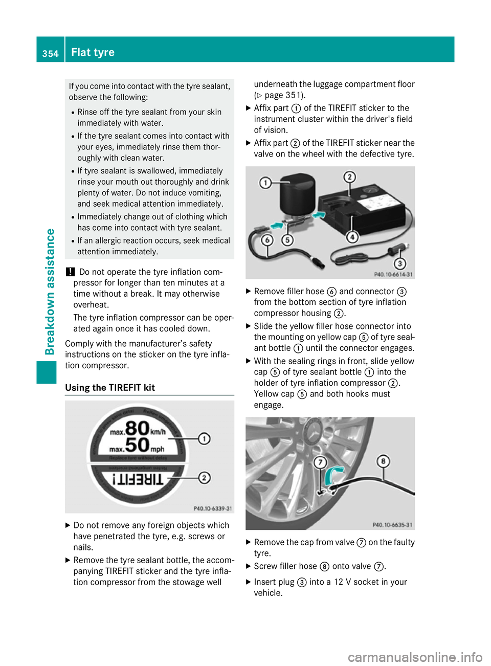
X Affix part :of the TIREFIT sticker to the
instrument cluster within the driver's field
of vision.
X Affix part ;of the TIREFIT sticker near the
valve on the wheel with the defective tyre. X
Remove filler hose Band connector =
from the bottom section of tyre inflation
compressor housing ;.
X Slide the yellow filler hose connector into
the mounting on yellow cap Aof tyre seal-
ant bottle :until the connector engages.
X With the sealing rings in front, slide yellow
cap Aof tyre sealant bottle :into the
holder of tyre inflation compressor ;.
Yellow cap Aand both hooks must
engage. X
Remove the cap from valve Con the faulty
tyre.
X Screw filler hose Donto valve C.
X Insert plug =into a 12 V socket in your
vehicle. 354
Flat tyreBreakdown assistance
Page 358 of 421
Observe the notes on sockets
(Y
page 328).
X Turn the key to position 1in the ignition
lock (Y page 165).
X Press on and off switch ?on the tyre infla-
tion compressor to ON.
The tyre inflation compressor is switched
on. The tyre is inflated.
First, tyre sealant is pumped into the tyre.
The pressure may briefly rise to approx-
imately 500 kPa (5 bar/73 psi).
Do not switch off the tyre inflation com-
pressor during this phase.
X Let the tyre inflation compressor run for a
maximum of ten minutes. The tyre should
then have attained a pressure of at least
200 kPa (2.0 bar/29 psi).
If a pressure of 200 kPa (2.0 bar/29 psi) has been attained after five minutes, see "Tyre
pressure reached" (Y page 355).
If a tyre pressure of 200 kPa (2.0 bar/29 psi)
has not been attained after five minutes, see "Tyre pressure not reached" (Y page 355).
If tyre sealant leaks out, make sure you clean
the affected area as quickly as possible. It is
preferable to use clear water.
If you get tyre sealant on your clothing, have it cleaned as soon as possible with perchloro-
ethylene.
Tyre pressure not reached If a tyre pressure of 200 kPa (2.0 bar/29 psi)
has not been attained after ten minutes:
X Switch off the tyre inflation compressor.
X Unscrew the filler hose from the valve of
the faulty tyre.
Please note that tyre sealant may leak out
when unscrewing the filler hose.
X Very slowly drive forwards or reverse
approximately 10 m.
X Pump up the tyre again.
After a maximum of ten minutes, the tyre
pressure must be at least 200 kPa (2.0 bar/
29 psi). G
WARNING
If the required tyre pressure is not reached
after the specified time, the tyre is too badly
damaged. The tyre sealant cannot repair the
tyre in this instance. Damaged tyres and a tyre pressure that is too low can significantly
impair the vehicle's braking and driving char-
acteristics. There is a risk of accident.
Do not continue driving. Contact a qualified
specialist workshop.
Tyre pressure reached G
WARNING
A tyre temporarily sealed with tyre sealant
impairs the driving characteristics and is not
suitable for higher speeds. There is a risk of
accident.
You should therefore adapt your driving style
accordingly and drive carefully. Do not exceed the specified maximum speed with a tyre that
has been repaired using tyre sealant.
The maximum permissible speed for a tyre
sealed with tyre sealant is 80 km/h. The
upper part of the TIREFIT sticker must be
affixed to the instrument cluster where it will be easily seen by the driver.
! After use, excess tyre sealant may run out
of the filler hose. This could cause stains.
Therefore, place the filler hose in the plastic
bag which contained the TIREFIT kit. H
Environmental note
Have the used tyre sealant bottle disposed of
professionally, e.g. at a qualified specialist
workshop.
If a tyre pressure of 200 kPa (2.0 bar/29 psi)
has been attained after ten minutes:
X Switch off the tyre inflation compressor.
X Unscrew the filler hose from the valve of
the faulty tyre. Flat tyre
355Breakdown assistance Z