2015 MERCEDES-BENZ CLA SHOOTING BRAKE buttons
[x] Cancel search: buttonsPage 154 of 421

Only change the temperature setting in
small increments. Start at 22 †.
Setting the air distribution
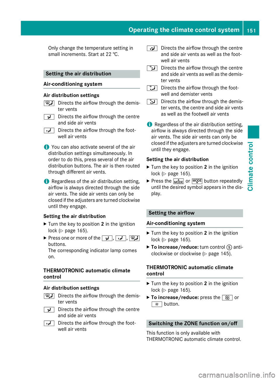
Air-conditioning system Air distribution settings
¯
Directs the airflow through the demis-
ter vents
P Directs the airflow through the centre
and side air vents
O Directs the airflow through the foot-
well air vents
i You can also activate several of the air
distribution settings simultaneously. In
order to do this, press several of the air
distribution buttons. The air is then routed
through different air vents.
i Regardless of the air distribution setting,
airflow is always directed through the side
air vents. The side air vents can only be
closed if the adjusters are turned clockwise until they engage.
Setting the air distribution X Turn the key to position 2in the ignition
lock (Y page 165).
X Press one or more of the P,O,¯
buttons.
The corresponding indicator lamp comes
on.
THERMOTRONIC automatic climate
control Air distribution settings
¯
Directs the airflow through the demis-
ter vents
P Directs the airflow through the centre
and side air vents
O Directs the airflow through the foot-
well air vents S
Directs the airflow through the centre
and side air vents as well as the foot-
well air vents
b Directs the airflow through the centre
and side air vents as well as the demis-
ter vents
a Directs the airflow through the foot-
well and demister vents
_ Directs the airflow through the demis-
ter vents, the centre and side air vents
as well as the footwell air vents
i Regardless of the air distribution setting,
airflow is always directed through the side
air vents. The side air vents can only be
closed if the adjusters are turned clockwise until they engage.
Setting the air distribution
X Turn the key to position 2in the ignition
lock (Y page 165).
X Press the ÉorË button repeatedly
until the desired symbol appears in the dis- play. Setting the airflow
Air-conditioning system X
Turn the key to position 2in the ignition
lock (Y page 165).
X To increase/reduce: turn controlAanti-
clockwise or clockwise (Y page 145).
THERMOTRONIC automatic climate
control X
Turn the key to position 2in the ignition
lock (Y page 165).
X To increase/reduce: press theKor
I button. Switching the ZONE function on/off
This function is only available with
THERMOTRONIC automatic climate control. Operating the climate control system
151Climate control
Page 162 of 421

ing temperature is reached. If this is the case,
the y symbol appears in the remote con-
trol display and the running time is zero
minutes.
Setting the departure time
Make sure that the time set in the vehicle is
correct before setting the departure time (see the separate operating instructions). Other-
wise, the auxiliary heating may switch on at
the wrong time and at an unsuitable location.
When setting the departure time, observe the important safety notes (Y page 156).
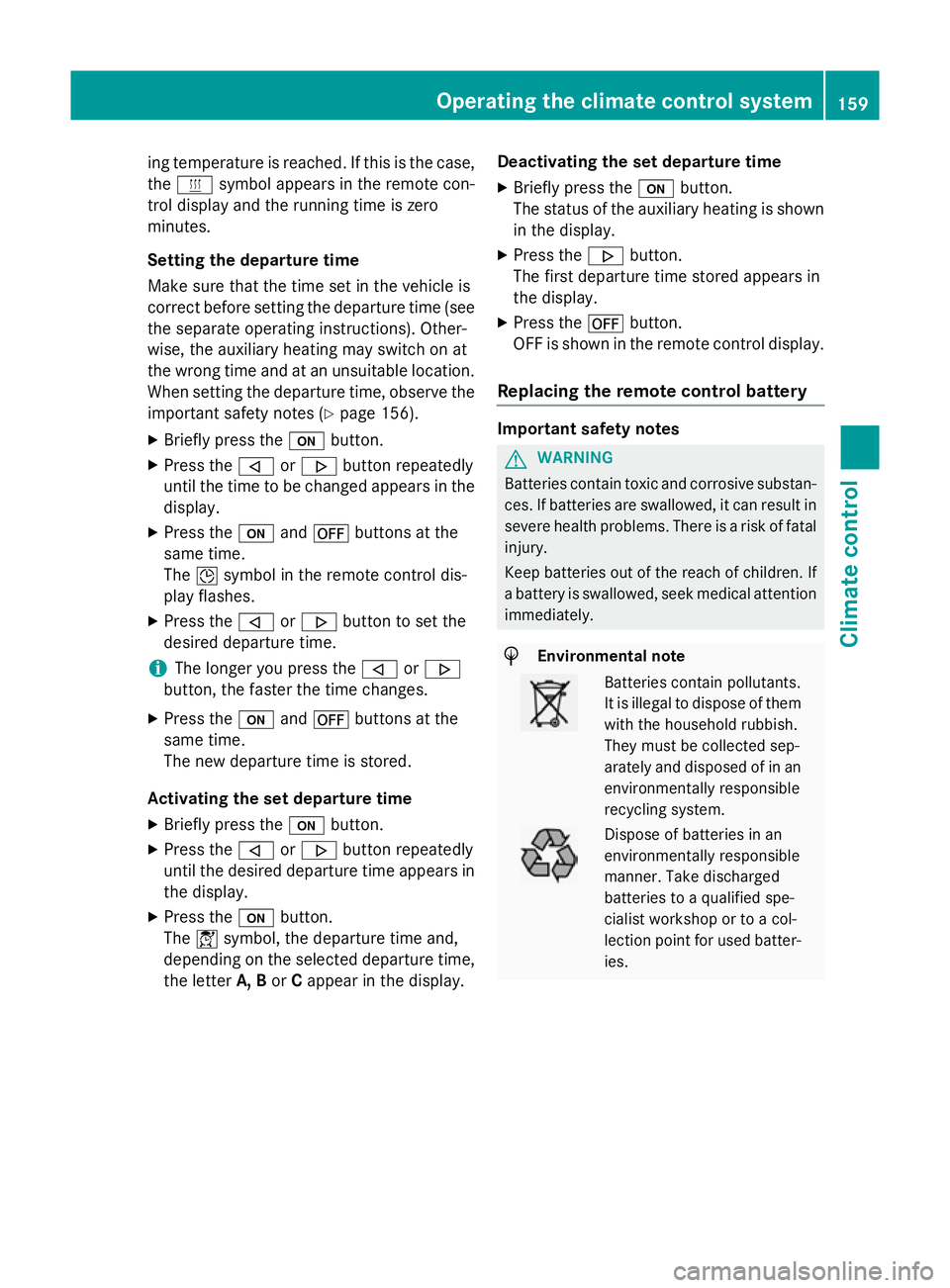
X Briefly press the ubutton.
X Press the ,or. button repeatedly
until the time to be changed appears in the display.
X Press the uand^ buttons at the
same time.
The Îsymbol in the remote control dis-
play flashes.
X Press the ,or. button to set the
desired departure time.
i The longer you press the
,or.
button, the faster the time changes.
X Press the uand^ buttons at the
same time.
The new departure time is stored.
Activating the set departure time X Briefly press the ubutton.
X Press the ,or. button repeatedly
until the desired departure time appears in the display.
X Press the ubutton.
The Ísymbol, the departure time and,
depending on the selected departure time, the letter A, BorCappear in the display. Deactivating the set departure time
X Briefly press the ubutton.
The status of the auxiliary heating is shown in the display.
X Press the .button.
The first departure time stored appears in
the display.
X Press the ^button.
OFF is shown in the remote control display.
Replacing the remote control battery Important safety notes
G
WARNING
Batteries contain toxic and corrosive substan- ces. If batteries are swallowed, it can result in
severe health problems. There is a risk of fatal injury.
Keep batteries out of the reach of children. If
a battery is swallowed, seek medical attention immediately. H
Environmental note Batteries contain pollutants.
It is illegal to dispose of them
with the household rubbish.
They must be collected sep-
arately and disposed of in anenvironmentally responsible
recycling system. Dispose of batteries in an
environmentally responsible
manner. Take discharged
batteries to a qualified spe-
cialist workshop or to a col-
lection point for used batter-
ies. Operating the climate control system
159Climate control Z
Page 250 of 421

The segments between the speed of the
vehicle in front and the stored speed light
up. Rev counter
! Do not drive in the overrevving range.
Doing so will damage the engine.
The red band in the rev counter indicates the
engine's overrevving range.
The engine is limited within a range to protect the engine when the red band is reached. Outside temperature display
You should pay special attention to road con-
ditions when temperatures are around freez-
ing point.
Bear in mind that the outside temperature
display indicates the measured air tempera-
ture and not the road surface temperature.
The outside temperature display is in the mul- tifunction display (Y page 249).
There is a short delay before a change in out- side temperature appears in the multifunc-
tion display. Coolant temperature gauge
G
WARNING
If you open the bonnet while the engine is
overheating or while there is a fire in the
engine compartment, you could come into
contact with hot gases or other leaking ser-
vice products. There is a danger of injury.
Allow an overheating engine to cool down
before opening the bonnet. If there is a fire in the engine compartment, leave the bonnet
closed and notify the fire brigade.
The coolant temperature gauge is in the
instrument cluster on the right-hand side
(Y page 32). Under normal operating conditions and with
the specified coolant level, the coolant tem-
perature may rise to 120 †.
At high outside temperatures and when driv-
ing uphill, the coolant temperature may rise
to the end of the scale. Operating the on-board computer
Overview :
Multifunction display
; Right control panel
= Left control panel
X To activate the on-board computer: turn
the key to position 1in the ignition lock.
You can control the multifunction display and
the settings in the on-board computer using
the buttons on the multifunction steering
wheel. Displays and operation
247On-board computer and displays Z
Page 252 of 421

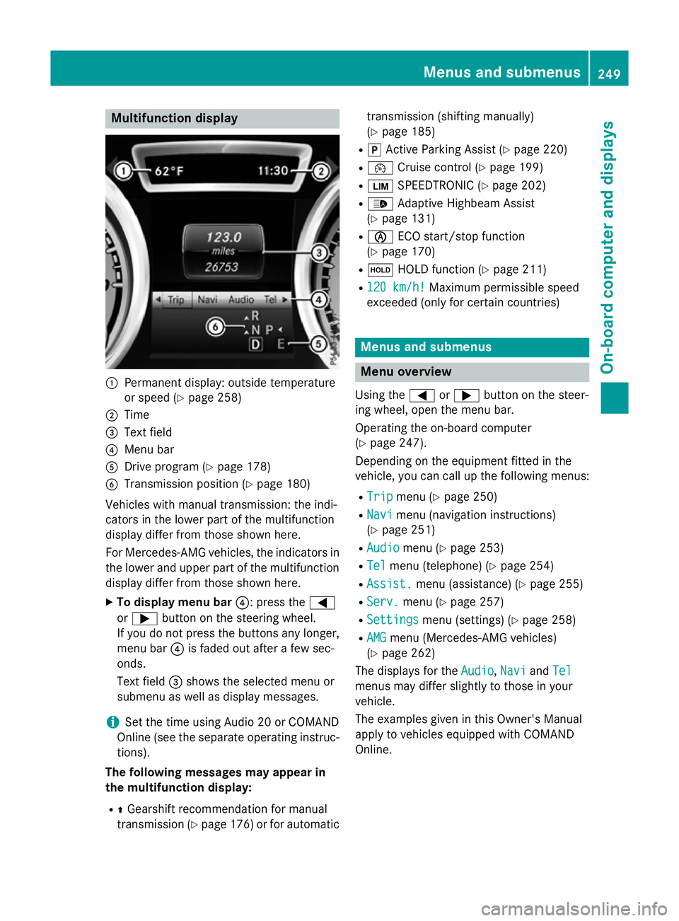
Multifunction display
:
Permanent display: outside temperature
or speed (Y page 258)
; Time
= Text field
? Menu bar
A Drive program (Y page 178)
B Transmission position (Y page 180)
Vehicles with manual transmission: the indi-
cators in the lower part of the multifunction
display differ from those shown here.
For Mercedes-AMG vehicles, the indicators in
the lower and upper part of the multifunction display differ from those shown here.
X To display menu bar ?: press the=
or ; button on the steering wheel.
If you do not press the buttons any longer, menu bar ?is faded out after a few sec-
onds.
Text field =shows the selected menu or
submenu as well as display messages.
i Set the time using Audio 20 or COMAND
Online (see the separate operating instruc-
tions).
The following messages may appear in
the multifunction display:
R ZGearshift recommendation for manual
transmission (Y page 176) or for automatic transmission (shifting manually)
(Y
page 185)
R j Active Parking Assist (Y page 220)
R ¯ Cruise control (Y page 199)
R È SPEEDTRONIC (Y page 202)
R _ Adaptive Highbeam Assist
(Y page 131)
R è ECO start/stop function
(Y page 170)
R ë HOLD function (Y page 211)
R 120 km/h!
120 km/h! Maximum permissible speed
exceeded (only for certain countries) Menus and submenus
Menu overview
Using the =or; button on the steer-
ing wheel, open the menu bar.
Operating the on-board computer
(Y page 247).
Depending on the equipment fitted in the
vehicle, you can call up the following menus:
R Trip Trip menu (Y page 250)
R Navi
Navi menu (navigation instructions)
(Y page 251)
R Audio
Audio menu (Y page 253)
R Tel
Tel menu (telephone) (Y page 254)
R Assist.
Assist. menu (assistance) (Y page 255)
R Serv.
Serv. menu (Y page 257)
R Settings
Settings menu (settings) (Y page 258)
R AMG
AMG menu (Mercedes-AMG vehicles)
(Y page 262)
The displays for the Audio
Audio,Navi
NaviandTel
Tel
menus may differ slightly to those in your
vehicle.
The examples given in this Owner's Manual
apply to vehicles equipped with COMAND
Online. Menus and submenus
249On-board computer and displays Z
Page 333 of 421

You must observe the legal requirements for
the country in which you are currently driving when operating mobile communications
equipment in the vehicle.
If it is permitted by law to operate communi-
cations equipment while the vehicle is in
motion, you may only do so if the traffic sit-
uation permits. You may otherwise be dis-
tracted from the traffic conditions, cause an
accident and injure yourself and others.
Excessive levels of electromagnetic radiation
may cause damage to your health and to the
health of others. The use of an exterior aerial
takes into consideration the scientific discus- sion surrounding the possible health risk
posed by electromagnetic fields.
Mercedes-Benz recommends the use of an
approved exterior aerial. This ensures:
R optimal mobile phone reception quality in
the vehicle
R that mutual interference between the vehi-
cle electronics and mobile phones is mini-
mised
An exterior aerial has the following advan-
tages:
R it conducts the electromagnetic fields gen-
erated by a wireless device to the exterior
R the field strength in the vehicle interior is
lower than in a vehicle that does not have
an exterior aerial
Information on retrofitting two-way radios
and mobile phones (RF transmitters)
(Y page 400).
General notes There are various mobile phone brackets that
may be fitted in your vehicle; in some cases,
these are country-specific. More information on suitable mobile phones,
mobile phone brackets and on connecting
Bluetooth ®
-capable mobile phones to
COMAND Online/Audio 20 can be obtained:
R at your Mercedes-Benz Service Centre
R on the Internet at http://www.mercedes-
benz.com/connect
The functions and services available when
you use the phone depend on your mobile
phone model and service provider.
Using a mobile phone To connect a mobile phone to the exterior
aerial and charge it, insert it into the mobile
phone bracket.
X Open the telephone compartment
(Y page 318).
X Place the mobile phone bracket into the
pre-installed fitting; see the separate instal-
lation instructions for the mobile phone fit-
ting.
X Insert the mobile phone into the mobile
phone bracket; see the separate installa-
tion instructions for the mobile phone fit-
ting.
i The mobile phone can also be operated
without being in the bracket. However, the charging function and aerial function are
not available.
In order to use Bluetooth ®
(SAP profile) on
your telephone module, you must first insert
the telephone module into the pre-installed
fitting. This connects it to the exterior aerial.
If you wish to charge the mobile phone, then
you must connect it to a USB port.
Further information on the telephone module
with Bluetooth ®
(SAP profile) can be found in
the Digital Owner's Manual.
Operating the mobile phone You can operate the telephone using the
6 and~ buttons on the multifunction
steering wheel. You can operate other mobile 330
FeaturesStowing and features