Page 316 of 407
753
Maintenance
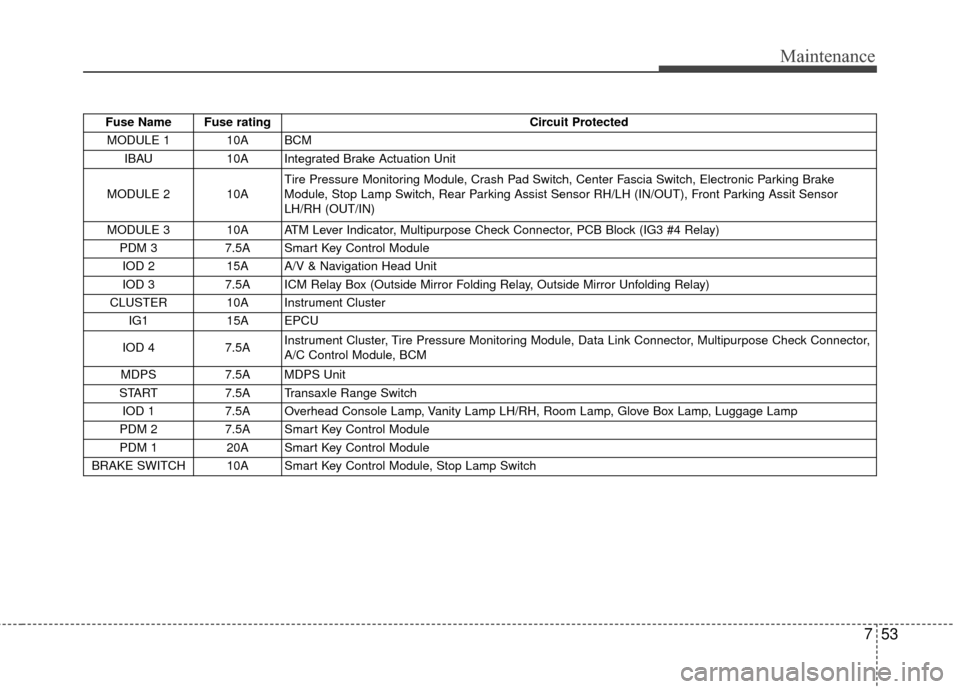
Fuse Name Fuse ratingCircuit Protected
MODULE 1 10A BCM IBAU 10A Integrated Brake Actuation Unit
MODULE 2 10A Tire Pressure Monitoring Module, Crash Pad Switch, Center Fascia Switch, Electronic Parking Brake
Module, Stop Lamp Switch, Rear Parking Assist Sensor RH/LH (IN/OUT), Front Parking Assit Sensor
LH/RH (OUT/IN)
MODULE 3 10A ATM Lever Indicator, Multipurpose Check Connector, PCB Block (IG3 #4 Relay) PDM 3 7.5A Smart Key Control Module
IOD 2 15A A/V & Navigation Head Unit
IOD 3 7.5A ICM Relay Box (Outside Mirror Folding Relay, Outside Mirror Unfolding Relay)
CLUSTER 10A Instrument Cluster IG1 15A EPCU
IOD 4 7.5A Instrument Cluster, Tire Pressure Monitoring Module, Data Link Connector, Multipurpose Check Connector,
A/C Control Module, BCM
MDPS 7.5A MDPS Unit
START 7.5A Transaxle Range Switch
IOD 1 7.5A Overhead Console Lamp, Vanity Lamp LH/RH, Room Lamp, Glove Box Lamp, Luggage Lamp
PDM 2 7.5A Smart Key Control Module
PDM 1 20A Smart Key Control Module
BRAKE SWITCH 10A Smart Key Control Module, Stop Lamp Switch
Page 318 of 407
755
Maintenance
Fuse Name Fuse ratingCircuit Protected
MDPS 80A MDPS Unit
ALT 150A Alternator
B+1 50A Smart Junction Block (Fuse - (S/HEATER FRT, TAIL GATE OPEN, DR LOCK, P/WINDOW LH, P/WINDOW
RH, MODULE 7))
B+2 50A Smart Junction Block (Fuse - (STOP LAMP) Arisu-LT2)
B+3 50A Smart Junction Block (Fuse - (PDM 1, PDM 2, BRAKE SWITCH, Leak Current Autocut Device) IPS1,
Arisu-LT1)
IG2 40A PCB Block (Button Start (IG2) Relay)
POWER OUTLET 20A Power Outlet Relay OBC 10A OBC Unit, Rear Heated Relay
BMS 10A BMS Control Module
EPCU 20A EPCU
CHARGER 2 10A Normal Charge Port Lmap C/FAN 40A COOLING FAN 1 Relay, COOLING FAN 2 Relay
RR HTD 40A Rear Heated Relay IBAU 2 30A Integrated Brake Actuation Unit
IBAU 1 40A Integrated Brake Actuation Unit
Page 319 of 407
Maintenance
56
7
Fuse Name Fuse rating Circuit Protected
IG1 40A Button Start (ACC) Relay, Button Start (IG1) Relay
BLOWER 40A Blower Relay IG3 1 30A IG3 #1/#2/#3/#4/#5 Relay
EPB 1 30A Electronic Parking Brake Module
EPB 2 30A Electronic Parking Brake Module
IG3 2 10A Blower Relay, A/C Control Module, A/C Compressor, E/R Junction Block (Cooling Fan 1/2 Relay), Heater
Assembly (PTC Heater)
CHARGER 1 10A OBC Unit, BMS Control Module EWP 10A Electronic Water Pump
IG3 3 15A EPCU, Transaxle Range Switch, A/V & Navigation Head Unit, Instrument Cluster
HORN 15A Horn Relay
B/UP LAMP 10A Transaxle Range Switch, EPCU
BATTERY C/FAN 25A Battery C/FAN Relay
No. Relay Name Type
E41 Power Outlet Relay PLUG MICRO
E42 C/FAN 1 Relay PLUG MICRO
E43 RR HTD Relay PLUG MICRO
E44 C/FAN 2 Relay PLUG MINI
Page 321 of 407
Maintenance
58
7
LIGHT BULBS
Use only the bulbs of the specified
wattage.
If you don’t have necessary tools, the correct bulbs and the expertise,
consult an authorized Kia dealer. In
many cases, it is difficult to replace
vehicle light bulbs because other
parts of the vehicle must be
removed before you can get to the
bulb. This is especially true if you
have to remove the headlight
assembly to get to the bulb(s).
Removing/installing the headlight
assembly can result in damage to
the vehicle.
Do not install additional bulb or LED. If you install that, the lamp
may not be operated properly and
fuse box or electric wiring system
may have problem.Front light replacement
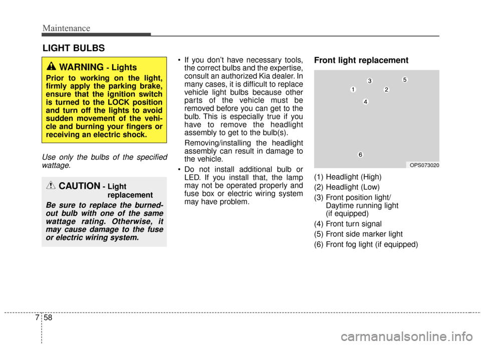
(1) Headlight (High)
(2) Headlight (Low)
(3) Front position light/ Daytime running light
(if equipped)
(4) Front turn signal
(5) Front side marker light
(6) Front fog light (if equipped)
WARNING - Lights
Prior to working on the light,
firmly apply the parking brake,
ensure that the ignition switch
is turned to the LOCK position
and turn off the lights to avoid
sudden movement of the vehi-
cle and burning your fingers or
receiving an electric shock.
CAUTION- Light replacement
Be sure to replace the burned-out bulb with one of the samewattage rating. Otherwise, itmay cause damage to the fuseor electric wiring system.
OPS073020
Page 331 of 407

Maintenance
68
7
APPEARANCE CARE
Exterior care
Exterior general caution
It is very important to follow the label
directions when using any chemical
cleaner or polish. Read all warning
and caution statements that appear
on the label.
Finish maintenance
Washing
To help protect your vehicle’s finish
from rust and deterioration, wash it
thoroughly and frequently at least
once a month with lukewarm or cold
water.
If you use your vehicle for off-road
driving, you should wash it after each
off-road trip. Pay special attention to
the removal of any accumulation of
salt, dirt, mud, and other foreign
materials. Make sure the drain holes
in the lower edges of the doors and
rocker panels are kept clear and
clean.
Insects, tar, tree sap, bird droppings,
industrial pollution and similar
deposits can damage your vehicle’s
finish if not removed immediately. Even prompt washing with plain
water may not completely remove all
these deposits. A mild soap, safe for
use on painted surfaces, may be
used.
After washing, rinse the vehicle thor-
oughly with lukewarm or cold water.
Do not allow soap to dry on the fin-
ish.
After washing the vehicle, test the
brakes while driving slowly to see if
they have been affected by water. If
braking performance is impaired, dry
the brakes by applying them lightly
while maintaining a slow forward
speed.
Page 343 of 407
Specifications & Consumer information
68
LubricantVolume Classification
Reduction gear oil 1.3±0.1
l
(1.4±0.1 US qt.) 75W/85, GL-4
Coolant 5.1
l
(5.39 US qt.) Mixture of antifreeze and water
(Ethylene glycol base coolant for aluminum radiator)
Brake fluid FMVSS116 DOT-3 or DOT-4
RECOMMENDED LUBRICANTS AND CAPACITIES
To help achieve proper performance, durability, use only lubricants of the proper quality for your vehicle.
These lubricants and fluids are recommended for use in your vehicle.
Page 366 of 407
21
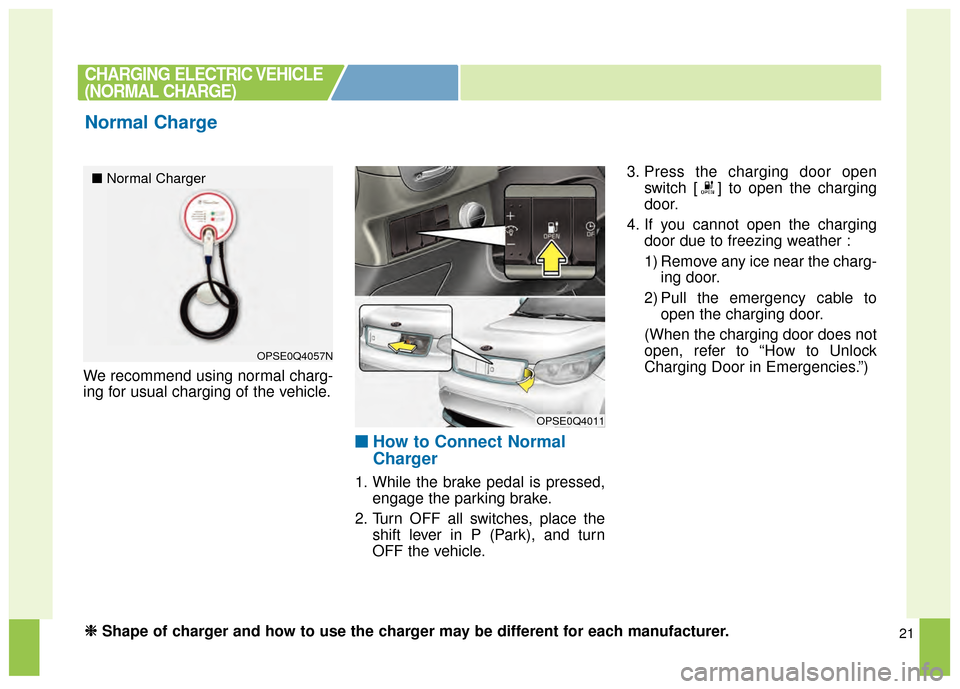
We recommend using normal charg-
ing for usual charging of the vehicle.
■ ■How to Connect Normal
Charger
1. While the brake pedal is pressed,
engage the parking brake.
2. Turn OFF all switches, place the shift lever in P (Park), and turn
OFF the vehicle. 3. Press the charging door open
switch [ ] to open the charging
door.
4. If you cannot open the charging door due to freezing weather :
1) Remove any ice near the charg-ing door.
2) Pull the emergency cable to open the charging door.
(When the charging door does not
open, refer to “How to Unlock
Charging Door in Emergencies.”)
CHARGING ELECTRIC VEHICLE
(NORMAL CHARGE)
Normal Charge
OPSE0Q4057N
OPSE0Q4011
■ Normal Charger
❈
❈
Shape of charger and how to use the charger may be different for each manufacturer.
Page 371 of 407
26
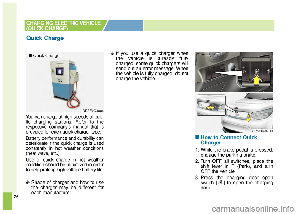
You can charge at high speeds at pub-
lic charging stations. Refer to the
respective company's manual that is
provided for each quick charger type.
Battery performance and durability can
deteriorate if the quick charge is used
constantly in hot weather conditions
(heat wave, etc.)
Use of quick charge in hot weather
condition should be minimized in order
to help prolong high voltage battery life.
❈Shape of charger and how to use
the charger may be different for
each manufacturer. ❈
If you use a quick charger when
the vehicle is already fully
charged, some quick chargers will
send out an error message. When
the vehicle is fully charged, do not
charge the vehicle.
■ ■
How to Connect Quick
Charger
1. While the brake pedal is pressed,
engage the parking brake.
2. Turn OFF all switches, place the shift lever in P (Park), and turn
OFF the vehicle.
3. Press the charging door open switch [ ] to open the charging
door.
Quick Charge
CHARGING ELECTRIC VEHICLE
(QUICK CHARGE)
OPSE0Q4004
OPSE0Q4011
■ Quick Charger