Page 276 of 678

way as the air bags inflate to their full size. The Advanced
Front Air Bags fully inflate in less time than it takes to
blink your eyes. The air bags then quickly deflate while
helping to restrain the driver and front passenger.
Knee Impact Bolsters
The Knee Impact Bolsters help protect the knees of the
driver and front passenger, and position the front occu-
pants for improved interaction with the Advanced Front
Air Bags.
WARNING!
•Do not drill, cut, or tamper with the knee impact
bolsters in any way.
•Do not mount any accessories to the knee impact
bolsters such as alarm lights, stereos, citizen band
radios, etc.
Supplemental Driver Knee Air Bag
This vehicle is equipped with a Supplemental Driver
Knee Air Bag mounted in the instrument panel below the
steering column. The Supplemental Driver Knee Air Bag
provides enhanced protection during a frontal impact by
working together with the seat belts, pretensioners, and
Advanced Front Air Bags.
Supplemental Side Air Bags
Your vehicle is equipped with two types of side air bags:
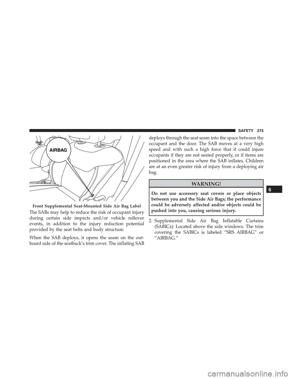
1. Supplemental Seat-Mounted Side Air Bags (SABs):
Located in the outboard side of the front seats. The
SABs are marked with a “SRS AIRBAG” or “AIRBAG”
label sewn into the outboard side of the seats.
274 SAFETY
Page 277 of 678

The SABs may help to reduce the risk of occupant injury
during certain side impacts and/or vehicle rollover
events, in addition to the injury reduction potential
provided by the seat belts and body structure.
When the SAB deploys, it opens the seam on the out-
board side of the seatback’s trim cover. The inflating SAB
deploys through the seat seam into the space between the
occupant and the door. The SAB moves at a very high
speed and with such a high force that it could injure
occupants if they are not seated properly, or if items are
positioned in the area where the SAB inflates. Children
are at an even greater risk of injury from a deploying air
bag.
WARNING!
Do not use accessory seat covers or place objects
between you and the Side Air Bags; the performance
could be adversely affected and/or objects could be
pushed into you, causing serious injury.
2. Supplemental Side Air Bag Inflatable Curtains
(SABICs): Located above the side windows. The trim
covering the SABICs is labeled “SRS AIRBAG” or
“AIRBAG.”
Front Supplemental Seat-Mounted Side Air Bag Label
6
SAFETY 275
Page 279 of 678

WARNING!
•Your vehicle is equipped with left and right
Supplemental Side Air Bag Inflatable Curtains
(SABICs). Do not stack luggage or other cargo up
high enough to block the deployment of the
SABICs. The trim covering above the side win-
dows where the SABIC and its deployment path
are located should remain free from any obstruc-
tions.
•Your vehicle is equipped with SABICs. In order for
the SABICs to work as intended, do not install any
accessory items in your vehicle which could alter
the roof. Do not add an aftermarket sunroof to your
vehicle. Do not add roof racks that require perma-
nent attachments (bolts or screws) for installation
on the vehicle roof. Do not drill into the roof of the
vehicle for any reason.
The SABICs and SABs (“Side Air Bags”) are designed to
activate in certain side impacts and certain rollover
events. The Occupant Restraint Controller (“ORC”) de-
termines whether the deployment of the Side Air Bags in
a particular side impact or rollover event is appropriate,
based on the severity and type of collision. Vehicle
damage by itself is not a good indicator of whether or not
Side Air Bags should have deployed.
Side Air Bags are a supplement to the seat belt restraint
system. Side Air Bags deploy in less time than it takes to
blink your eyes. Occupants, including children, who are
up against or very close to Side Air Bags can be seriously
injured or killed. Occupants, including children, should
never lean on or sleep against the door, side windows, or
area where the Side Air Bags inflate, even if they are in an
infant or child restraint.
6
SAFETY 277
Page 466 of 678
Mounting Fuse Cover and Locking Screw
Proceed as follows:
•Properly secure the fuse cover to the box, slide com-
pletely from top to bottom.
•Fully depress the screw, using the special screwdriver
supplied.
•Slowly turn the screw clockwise.
•Release the screw.
Battery Fuse Cover Location
1—FuseCoverTabs2—FuseCover
464 IN CASE OF EMERGENCY
Page 491 of 678

WARNING!(Continued)
•Do not use Tire Service Kit or drive the vehicle
under the following circumstances:
– If the puncture in the tire tread is approximately
1/4” (6 mm) or larger.
– If the tire has any sidewall damage.
– If the tire has any damage from driving with
extremely low tire pressure.
– If the tire has any damage from driving on a flat
tire.
– If the wheel has any damage.
– If you are unsure of the condition of the tire or
the wheel.
•Keep Tire Service Kit away from open flames or
heat source.
(Continued)
WARNING!(Continued)
•A loose Tire Service Kit thrown forward in a
collision or hard stop could endanger the occupants
of the vehicle. Always stow the Tire Service Kit in
the place provided. Failure to follow these warn-
ings can result in injuries that are serious or fatal to
you, your passengers, and others around you.
•Take care not to allow the contents of Tire Service
Kit to come in contact with hair, eyes, or clothing.
Tire Service Kit sealant is harmful if inhaled,
swallowed, or absorbed through the skin. It causes
skin, eye, and respiratory irritation. Flush immedi-
ately with plenty of water if there is any contact
with eyes or skin. Change clothing as soon as
possible, if there is any contact with clothing.
(Continued)
8
IN CASE OF EMERGENCY 489
Page 551 of 678

Use only manufacturer’s recommended brake fluid. Re-
fer to “Fluids, Lubricants, and Genuine Parts” in the
“Technical Data” section for further information.
WARNING!
•Use only manufacturer ’s recommended brake
fluid. Refer to “Fluids, Lubricants, and Genuine
Parts” in the “Technical Data” section for further
information. Using the wrong type of brake fluid
can severely damage your brake system and/or
impair its performance. The proper type of brake
fluid for your vehicle is also identified on the
original factory installed hydraulic master cylinder
reservoir.
(Continued)
WARNING!(Continued)
•To avoid contamination from foreign matter or
moisture, use only new brake fluid or fluid that has
been in a tightly closed container. Keep the master
cylinder reservoir cap secured at all times. Brake
fluid in a open container absorbs moisture from the
air resulting in a lower boiling point. This may
cause it to boil unexpectedly during hard or pro-
longed braking, resulting in sudden brake failure.
This could result in a collision.
•Overfilling the brake fluid reservoir can result in
spilling brake fluid on hot engine parts, causing
the brake fluid to catch fire. Brake fluid can also
damage painted and vinyl surfaces, care should be
taken to avoid its contact with these surfaces.
(Continued)
9
MAINTAINING AND CARING FOR YOUR VEHICLE 549
Page 563 of 678
TIRE SAFETY INFORMATION
Tire Markings
NOTE:
•P (Passenger) — Metric tire sizing is based on U.S.
design standards. P-Metric tires have the letter “P”
molded into the sidewall preceding the size designa-
tion. Example: P215/65R15 95H.
•European — Metric tire sizing is based on European
design standards. Tires designed to this standard have
the tire size molded into the sidewall beginning with
the section width. The letter#P#is absent from this tire
size designation. Example: 215/65R15 96H.
•LT (Light Truck) — Metric tire sizing is based on U.S.
design standards. The size designation for LT-Metric
tires is the same as for P-Metric tires except for the
letters “LT” that are molded into the sidewall preced-
ing the size designation. Example: LT235/85R16.
1—U.S.DOTSafetyStandardsCode (TIN)4—MaximumLoad
2—SizeDesignation 5—MaximumPressure3 — Service Description 6 — Treadwear, Traction andTemperature Grades
9
MAINTAINING AND CARING FOR YOUR VEHICLE 561
Page 566 of 678
EXAMPLE:
H= Speed Symbol
– A symbol indicating the range of speeds at which a tire can carry a load corresponding to
its load index under certain operating conditions
– The maximum speed corresponding to the speed symbol should only be achieved under
specified operating conditions (i.e., tire pressure, vehicle loading, road conditions, and
posted speed limits)
Load Identification:
Absence of the following load identification symbols on the sidewall of the tire indicates a Standard Load (SL)
tire:
•XL= Extra load (or reinforced) tire, or
•LL= Light load tire or
•C, D, E, F, G= Load range associated with the maximum load a tire can carry at a specified pressure
Maximum Load– Maximum load indicates the maximum load this tire is designed to carry
Maximum Pressure– Maximum pressure indicates the maximum permissible cold tire inflation pressure for this
tire
564 MAINTAINING AND CARING FOR YOUR VEHICLE