2015 FORD F750 lock
[x] Cancel search: lockPage 206 of 384

•Checking that the pitman arm (steering arm at steering gear)
mounting is tight and locked. Check system for leaks or hose chafing.
Repair immediately, if necessary.
•Maintaining proper steering gear and power steering pump lubricant
levels.
•Checking steering column joint bolts and steering linkage, particularly
for body-to-chassis clearance.
Steering Column Joint Bolts
As a good maintenance practice, check steering column joint bolt
tightness every 60000 miles (96000 kilometers) or annually, whichever
occurs first. Do not overtighten the bolts.
Hydraulic System
Whenever draining and refilling the power steering’s hydraulic system for
any reason, bleed air from the system before returning the vehicle to
service. Failure to bleed the hydraulic system properly can result in
degradation of power system performance.
Consult an authorized dealer who is aware of the proper procedures for
filling and bleeding the system.
Catalytic Converter (Diesel Engine)
Note:If your vehicle is equipped with a catalytic converter or muffler,
do not blend waste oil with diesel fuel. Operate only on ultra-low sulfur
(less than 15 parts per million sulfur) diesel fuel with a cetane value of
45 or higher.
If your diesel engine is equipped with a catalytic converter, it is
important to review the maintenance schedule to make sure proper
functioning of the catalytic converter. Also, take precautions not to
damage the catalytic converter when servicing your engine or storing
your vehicle.
Diesel Exhaust Fluid (DEF), Diesel Particulate Filter (DPF) and
Select Catalyst Reduction (SCR) System
See your engine operator’s manual for information about DEF, DPF and
SCR system service
Air Induction System
WARNING:When performing maintenance to any turbocharged
engine with engine air inlet piping disconnected, keep loose
clothing, jewelry and long hair away from the engine air inlet piping. A
turbocharger compressor air inlet protective shield should be installed
over the turbocharger air inlet to reduce the risk of personal injury or
death.
Maintenance205
2015 F-650/750(f67)
Owners Guide gf(ownloose), 1st Printing, December 2013
Canadian_French(fr_can)
Page 207 of 384

Perform a complete inspection of the air induction system annually.
In areas where road salt is used, disassemble the joints of each aluminum
component and inspect for salt build-up and presence of chlorine that
can cause aluminum particles to flake off and enter the engine
combustion chambers. If evidence of corrosion is found (usually at the
pipe connections), use a wire brush to clean the inside of the pipes and
inside the rubber hoses.
If pitting is evident at the joint ends of the intake pipes, use Motorcraft
Silicone Gasket and Sealant TA-30 to seal the joints. Make sure no
excess material, which can pull into the engine, is on the inside of the
pipes. If the service condition of the pipes, hoses or clamps is
questionable, replace the defective part(s).
Make sure to clean all dust and debris out of the pipes and couplings
with a clean, damp rag before reassembly.
Chassis-mounted Charge Air Cooler
Visually inspect the core assembly for debris and clogging of external fins
with the engine off. Before engine operation, remove any debris blocking
the core.
•Turbocharger-to-charge air cooler
•Charge air cooler-to-intake manifold pipe
•Mounting bracket
•Chassis-mounted charge air cooler core
Inspect air intake piping:
•Check for accumulation of salt deposits (where applicable). If
present, disassemble and clean the complete air intake piping system.
If pitting is evident on the intake piping, use Motorcraft Silicone
Gasket and Sealant TA-30 to seal joints against leakage.
•Check for loose hoses and clamps.
•Check for ruptured or collapsed hoses.
•Check air cleaner housing for cracks.
Suspension Inspection
Note:Do not adjust air suspension height to any setting other than the
specified setting. Altering the height setting changes the driveline angle
and may result in unwarrantable component damage, such as
transmission component damage.
Verify drive axle air suspension height and height control valve
performance at engine oil change intervals.
206Maintenance
2015 F-650/750(f67)
Owners Guide gf(ownloose), 1st Printing, December 2013
Canadian_French(fr_can)
Page 208 of 384

Periodically check:
•Condition of spring leaves for evidence of fatigue, bending or
breakage.
•Condition of suspension mounting brackets and bushings.
•Torque rod mounting fasteners for tightness.
•For proper suspension alignment. Maintain proper alignment at all
times.
•U-bolts. After the chassis has been operating under load for
1000 miles (1600 kilometers) or six months (whichever comes first),
the U-bolt nuts must be re-torqued. Re-torque the U-bolt nuts every
36000 miles (60000 kilometers) thereafter. Clean and lubricate the
U-bolt and nut threads and seats to make sure a like new condition
when re-torqueing.
Note:SeeSpring U-bolt checklater in this chapter.
Supporting Your Vehicle for Service
WARNING:Do not use a jack when working under a vehicle. It
may give way, causing the vehicle to fall and result in property
damage, personal injury or death. Always use floor stands to support
the vehicle.
Prepare your vehicle for service repairs by doing the following:
1. Park your vehicle on a level, concrete floor.
2. Set the parking brake and block the wheels to prevent your vehicle
from moving.
3. Select a jack with a rated capacity sufficient to lift and hold up your
vehicle.
4. Raise your vehicle with the jack applied to the axle(s). Do not use
the bumper as a lifting point.
5. Support your vehicle with floor stands under the axle(s). When
servicing the axle or the suspension, support your vehicle with floor
stands under the frame side-members, preferably between the axles.
Frame and Tow Hooks
Your vehicle’s chassis is manufactured with frame rails of either HSLA
steel or heat-treated steel. Handle each in a specific manner to make
sure maximum service life. Consult the service manual or an authorized
dealer before attempting frame repair or modification.
It is important, particularly on vehicles that use tow hooks frequently, to
inspect the front and rear tow hooks for damage or a loose mounting.
Maintenance207
2015 F-650/750(f67)
Owners Guide gf(ownloose), 1st Printing, December 2013
Canadian_French(fr_can)
Page 210 of 384

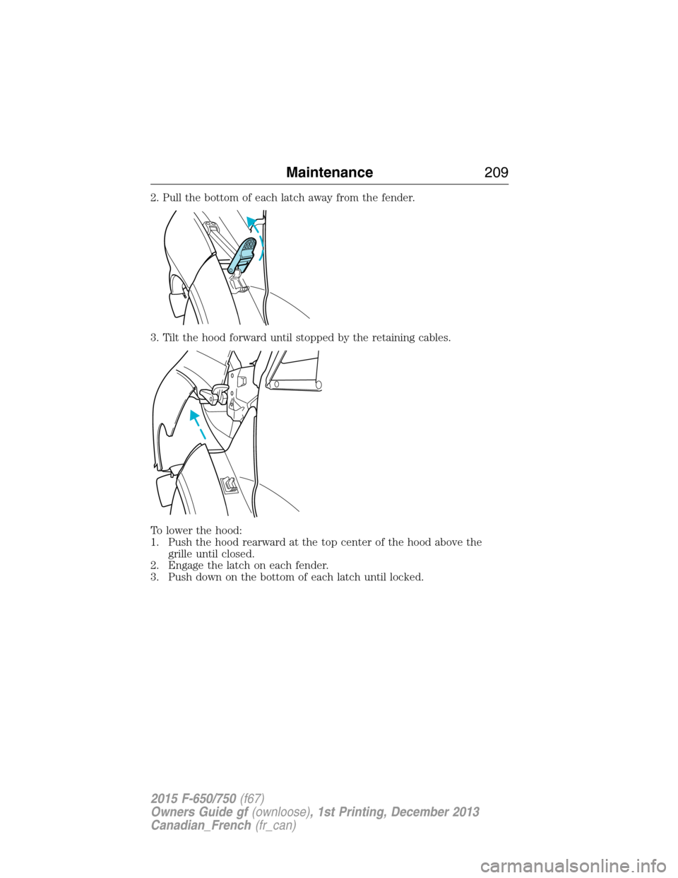
2. Pull the bottom of each latch away from the fender.
3. Tilt the hood forward until stopped by the retaining cables.
To lower the hood:
1. Push the hood rearward at the top center of the hood above the
grille until closed.
2. Engage the latch on each fender.
3. Push down on the bottom of each latch until locked.
Maintenance209
2015 F-650/750(f67)
Owners Guide gf(ownloose), 1st Printing, December 2013
Canadian_French(fr_can)
Page 212 of 384

Adding Engine Oil
Note:Do not remove the engine oil dipstick or the filler cap when the
engine is running.
Note:Do not add engine oil further than the MAX mark. Oil levels above
the MAX mark may cause engine damage.
Only use oils certified for gasoline engines by the
American Petroleum Institute (API). Oil with this
trademark symbol conforms to the current engine and
emission system protection standards and fuel
economy requirements of the International Lubricants
Specification Advisory Council (ILSAC), comprised of
U.S. and Japanese automobile manufacturers.
1. Check the engine oil level.
2. If the engine oil level is not within the normal range, add engine oil
that meets Ford specifications. SeeCapacities and Specifications
for more information. Remove the engine oil filler cap and use a
funnel to pour the engine oil into the opening.
3. Recheck the engine oil level. Make sure the oil level is not above the
normal operating range on the engine oil dipstick.
4. Put the dipstick back in completely.
5. Fully install the oil filler cap by turning it clockwise until it clicks or
stops turning.
ENGINE COOLANT CHECK
Diesel Engine
See your engine operator’s manual for information on checking and
adding engine coolant.
Fan Clutches
WARNING:Stay clear of the fan and fan area while the engine is
running or possible personal injury may occur.
Your vehicle’s cooling system is equipped with a viscous fan clutch
which:
•Helps control cooling, increases performance, improves fuel economy
and reduces noise.
•Bimetallic spring sensors control. Do not tamper with these sensors
as this may change their calibration or keep the fan clutch from
operating at all.
Maintenance211
2015 F-650/750(f67)
Owners Guide gf(ownloose), 1st Printing, December 2013
Canadian_French(fr_can)
Page 228 of 384

4. Allow the engine to idle for at least one minute.
5. Turn on the air conditioning and allow the engine to idle for at least
one minute.
6. Release the parking brake. With your foot on the brake pedal and
with the air conditioning on, put the transmission in positionP
(automatic transmission) or neutral (manual transmission) and allow
the engine to idle for at least one minute.Note:Not allowing the
engine to relearn the idle trim may adversely affect the idle quality of
your vehicle until the engine eventually relearns the idle trim.
7. Drive your vehicle to complete the relearning process.
If you disconnect the battery or install a new battery, you have to reset
the clock and radio settings after reconnecting the battery.
Always dispose of automotive
batteries in a responsible manner.
Follow your local authorized
standards for disposal. Call your
local authorized recycling center to
find out more about recycling
automotive batteries.
CHECKING THE WIPER BLADES
Run the tip of your fingers over the edge of the blade
to check for roughness.
Clean the wiper blades with washer fluid or water
applied with a soft sponge or cloth.
L
E
A
D
RETURN
RECYCLE
Maintenance227
2015 F-650/750(f67)
Owners Guide gf(ownloose), 1st Printing, December 2013
Canadian_French(fr_can)
Page 229 of 384

CHANGING THE WIPER BLADES
1. To remove the wiper blade, pull
the wiper arm away from your
vehicle. Pry open the lock cover
(A) with your thumb to release
the blade.
2. Press the retaining clip to
disengage the wiper blade, and
then pull the wiper blade down
(C) toward the windshield to
remove it from the arm.
3. To install the new wiper blade,
insert the wiper blade into the
wiper arm hook (B).
4. While holding the wiper arm,
push the wiper blade up and
away from the windshield.
5. Close the lock cover.
Replace wiper blades at least once per year for optimum performance.
Poor wiper quality can be improved by cleaning the wiper blades and the
windshield. SeeCleaning the windows and wiper bladesin theVehicle
Carechapter.
To prolong the life of the wiper blades, it is highly recommended to
scrape off the ice on the windshield before turning on the wipers. The
layer of ice has many sharp edges and can damage the micro edge of the
wiper rubber element.
AIR FILTER CHECK
Diesel Engine
See your engine operator’s manual for information on the engine air
filter.
Gasoline Engine
Note:Do not start your engine with the air cleaner removed and do not
remove it while the engine is running.
A
B
C
228Maintenance
2015 F-650/750(f67)
Owners Guide gf(ownloose), 1st Printing, December 2013
Canadian_French(fr_can)
Page 230 of 384

Note:Failure to use the correct air filter element may result in severe
engine damage. The customer warranty may be void for any damage to
the engine if the correct air filter element is not used.
See theScheduled Maintenancechapter for the appropriate intervals
for changing the air filter element.
When changing the air filter element, use only the Motorcraft air filter
element listed. SeeMotorcraft part numbersin theCapacities and
Specificationschapter.
1. Locate and disconnect the mass
air flow sensor electrical connector
on the air outlet tube.
2. Reposition the locking clip on the
connector (connector shown from
below for clarity). Squeeze the
connector and pull it off the air
outlet tube.
3. Clean the area around the air
tube-to-air cover connection to
prevent debris from entering the
system. Loosen the bolt on the air
tube clamp so the clamp is no
longer snug to the air tube. It is not
necessary to remove the clamp
completely.
4. Pull the air tube off the air
cleaner housing.
Maintenance229
2015 F-650/750(f67)
Owners Guide gf(ownloose), 1st Printing, December 2013
Canadian_French(fr_can)