2015 FORD F250 SUPER DUTY towing
[x] Cancel search: towingPage 198 of 470
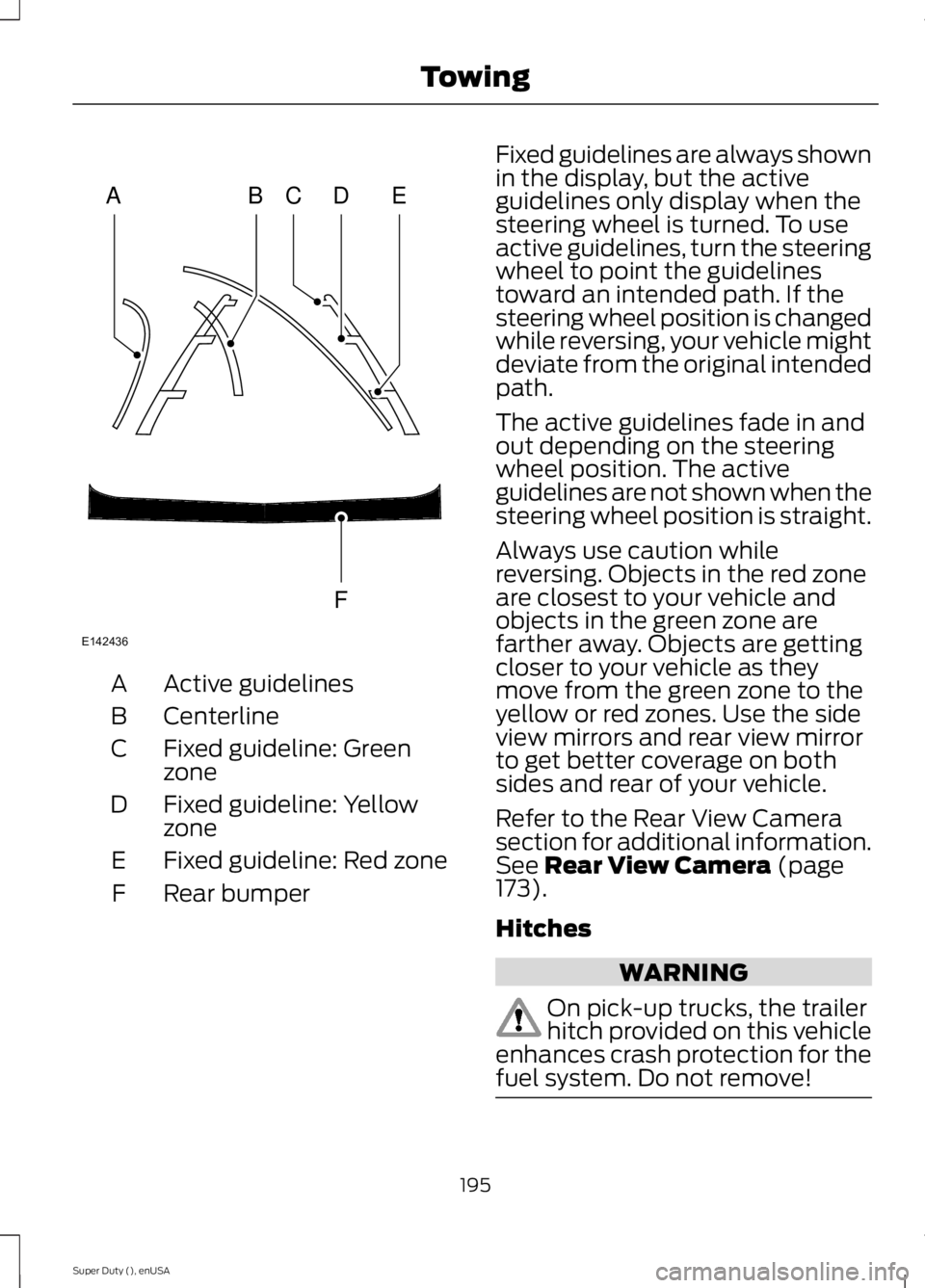
Active guidelinesA
CenterlineB
Fixed guideline: GreenzoneC
Fixed guideline: YellowzoneD
Fixed guideline: Red zoneE
Rear bumperF
Fixed guidelines are always shownin the display, but the activeguidelines only display when thesteering wheel is turned. To useactive guidelines, turn the steeringwheel to point the guidelinestoward an intended path. If thesteering wheel position is changedwhile reversing, your vehicle mightdeviate from the original intendedpath.
The active guidelines fade in andout depending on the steeringwheel position. The activeguidelines are not shown when thesteering wheel position is straight.
Always use caution whilereversing. Objects in the red zoneare closest to your vehicle andobjects in the green zone arefarther away. Objects are gettingcloser to your vehicle as theymove from the green zone to theyellow or red zones. Use the sideview mirrors and rear view mirrorto get better coverage on bothsides and rear of your vehicle.
Refer to the Rear View Camerasection for additional information.See Rear View Camera (page173).
Hitches
WARNING
On pick-up trucks, the trailerhitch provided on this vehicleenhances crash protection for thefuel system. Do not remove!
195
Super Duty (), enUSA
TowingABCD
F
E
E142436
Page 199 of 470
Do not use a hitch that eitherclamps onto the bumper orattaches to the axle. You mustdistribute the load in your trailerso that 10-15% for conventionaltowing or 15-25% for fifth wheeltowing of the total weight of thetrailer is on the tongue.
Weight-distributing Hitches
WARNING
Do not adjust aweight-distributing hitch toany position where the rearbumper of the vehicle is higherthan it was before attaching thetrailer. Doing so will defeat thefunction of the weight-distributinghitch, which may causeunpredictable handling, and could
result in serious personal injury.
When hooking-up a trailer using aweight-distributing hitch, alwaysuse the following procedure:
1. Park the loaded vehicle,without the trailer, on a levelsurface.
2.Measure the height to the topof your vehicle's front wheelopening on the fender. This isH1.
3.Attach the loaded trailer toyour vehicle without theweight-distributing barsconnected.
4.Measure the height to the topof your vehicle's front wheelopening on the fender a secondtime. This is H2.
5.Install and adjust the tensionin the weight-distributing barsso that the height of yourvehicle's front wheel openingon the fender is approximatelyhalfway between H1 and H2.
6.Check that the trailer is level orslightly nose down toward yourvehicle. If not, adjust the ballheight accordingly and repeatSteps 2-6.
Once the trailer is level or slightlynose down toward the vehicle:
•Lock the bar tension adjusterin place.
•Check that the trailer tonguesecurely attaches and locksonto the hitch.
•Install safety chains, lighting,and trailer brake controls asrequired by law or the trailermanufacturer.
Fifth-wheel Trailer Hitch (IfEquipped)
WARNINGS
The mounting pads in the bedare specifically designed forcertain fifth-wheel trailer hitchesand gooseneck ball hitches. Donot use these mounting pads forother purposes. Doing so couldresult in vehicle structural
196
Super Duty (), enUSA
Towing
Page 200 of 470
WARNINGS
damage, loss of vehicle control,and personal injury. Contact anauthorized dealer to purchasegooseneck and fifth-wheel hitchesthat are compatible with yourvehicle.
Towing trailers beyond themaximum limit of the towingsystem could result in vehiclestructural damage, loss of vehiclecontrol and personal injury.
The hitch rating listed on thetrailer hitch label is themaximum possible trailer rating.To find the maximum trailerweight allowed for your specificvehicle, consult an authorizeddealer or the RV & Trailer TowingGuide provided by an authorizeddealer.
Your vehicle may be equippedwith a fifth-wheel prep package.This package enables your vehicleto accept certain fifth-wheeltrailer hitches and gooseneck ballhitches. The fifth-wheel trailerhitch attaches to the fourmounting pads in the pick-up bed.An optional 7-pin trailer wiringconnector may be in the bed aswell. The gooseneck ball hitch isa separate mounting pad from thefifth-wheel hitch, located in thecenter of the bed.
Shorter pick-up boxes, such as the6½-foot box on the F-250 andF-350, provide less clearancebetween the cab and thefifth-wheel and gooseneck trailercompared to longer box pick-ups,such as an 8-foot box on theF-250 or F-350. When selecting atrailer and tow vehicle, it is criticalto check that this combinationprovides clearance between thefront of the trailer and tow vehiclefor turns up to 90 degrees. Failureto follow this recommendationcould result in the trailercontacting the cab of the towvehicle during tight turns that aretypical during low-speed parkingand turning maneuvers. Thiscontact could result in damage tothe trailer and tow vehicle.
Safety Chains
Note:Do not attach safety chainsto the bumper.
Always connect the safety chainsto the frame or hook retainers ofyour vehicle hitch.
To connect the safety chains,cross the chains under the trailertongue and allow enough slack forturning tight corners. Do not allowthe chains to drag on the ground.
197
Super Duty (), enUSA
Towing
Page 201 of 470
Trailer Brakes
WARNING
Do not connect a trailer'shydraulic brake systemdirectly to your vehicle's brakesystem. Your vehicle may not haveenough braking power and yourchances of having a collisiongreatly increase.
Electric brakes and manual,automatic or surge-type trailerbrakes are safe if you install themproperly and adjust them to themanufacturer's specifications. Thetrailer brakes must meet local andfederal regulations.
The rating for the tow vehicle'sbraking system operation is atthe gross vehicle weight rating,not the gross combined weightrating.
Separate functioning brakesystems are required for safecontrol of towed vehicles andtrailers weighing more than1500 pounds (680 kilograms)when loaded.
Integrated Trailer BrakeController (If Equipped)
WARNING
The Ford trailer brakecontroller has been verifiedto be compatible with trailershaving electric-actuated drumbrakes (one to four axles) andsome electric-over-hydraulicbrakes. It will not activatehydraulic surge-style trailerbrakes. It is the responsibility ofthe customer to ensure that thetrailer brakes are adjustedappropriately, functioningnormally and all electricconnections are properly made.Failure to do so may result in lossof vehicle control, crash or serious
injury.
When used properly, the trailerbrake controller assists in smoothand effective trailer braking bypowering the trailer’s electric orelectric-over-hydraulic brakeswith a proportional output basedon the towing vehicle’s brakepressure.
198
Super Duty (), enUSA
TowingB
A
E163166
Page 202 of 470
You can adjust the amount ofinitial trailer brake output byselecting one of three settingsthrough the message center.
Ford has tested the trailer brakecontroller to be compatible withseveral major brands ofelectric-over-hydraulic trailerbrakes. Contact an authorizeddealer for information on whichbrands you can use.
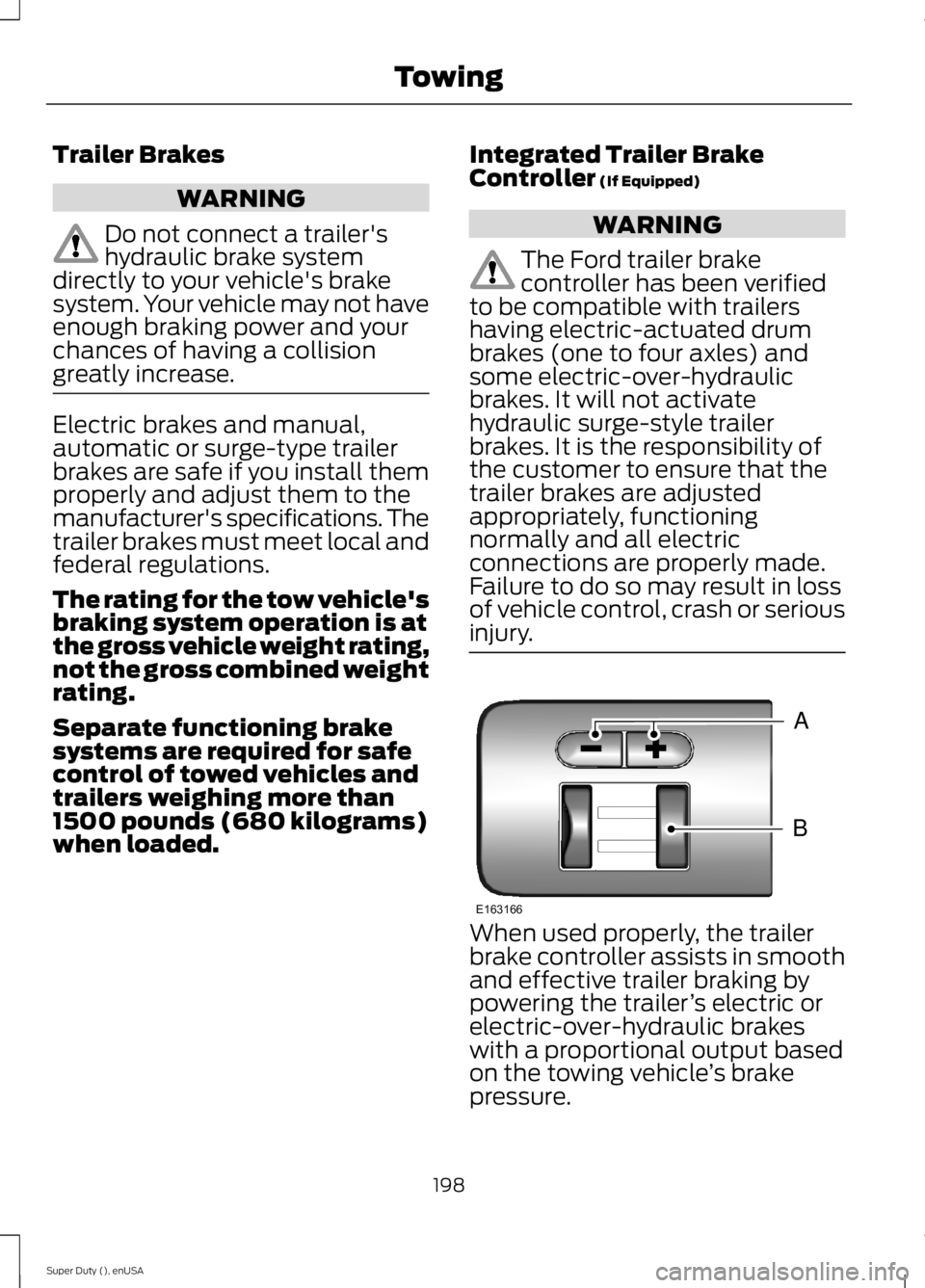
The controller user interfaceconsists of the following:
A: + and - (Gain adjustmentbuttons): Pressing these buttonsadjusts the controller's poweroutput to the trailer brakes in 0.5increments. You can increase thegain setting to 10.0 (maximumtrailer braking) or decrease it to 0(no trailer braking). Pressing andholding a button raises or lowersthe setting continuously. The gainsetting displays in the messagecenter as follows: TBC GAIN =XX.X.
B: Manual control lever: Slide thecontrol lever to the left to switchon the trailer's electric brakesindependent of the tow vehicle's.See the following Procedure foradjusting gain section forinstructions on proper use of thisfeature. If you use the manualcontrol while the brake is alsoapplied, the greater of the twoinputs determines the power sentto the trailer brakes.
•Stop lamps: Using the manualcontrol lever lights both thetrailer brake lamps and yourvehicle brake lamps except thecenter high-mount stop lamp,if you make the properelectrical connection to thetrailer. Pressing your vehiclebrake pedal also lights bothtrailer and vehicle brake lamps.
The controller shows gain setting,output bar graph, and trailerconnectivity status in theinformation display. They appearin the information display asfollows:
•TBC GAIN = XX.X NOTRAILER: Shows the currentgain setting during a givenignition cycle and when
adjusting the gain. This alsodisplays if you use the manualcontrol lever or make gainadjustments with no trailerconnected.
•TBC GAIN = XX.XOUTPUT=/ / / / / /: Displayswhen you push your vehicle'sbrake pedal, or upon use of themanual control. Bar indicatorslight in the information displayto indicate the amount ofpower going to the trailerbrakes relative to the brakepedal or manual control input.One bar indicates the leastamount of output; six barsindicate maximum output.
199
Super Duty (), enUSA
Towing
Page 203 of 470
•TRAILER CONNECTED:Displays when the systemsenses a correct trailer wiringconnection during a givenignition cycle.
•TRAILER DISCONNECTED:Displays, accompanied by asingle audible time, when thesystem senses a trailerconnection and then adisconnection, eitherintentional or unintentional,during a given ignition cycle. Italso displays if a truck ortrailer-wiring fault occurscausing the trailer to appeardisconnected. This messagecan also display if you use themanual control lever without atrailer connected.
Procedure for Adjusting Gain
Note:Only perform this procedurein a traffic-free environment atspeeds of approximately 20-25mph (30-40 km/h).
The gain setting sets the trailerbrake controller for the specifictowing condition. You shouldchange the setting as towingconditions change. Changes totowing conditions include trailerload, vehicle load, road conditionsand weather.
The gain should be set to providethe maximum trailer brakingassistance while making sure thetrailer wheels do not lock whenusing the brakes. Locked trailerwheels may lead to trailerinstability.
1.Make sure the trailer brakes arein good working condition,functioning normally andproperly adjusted. See yourtrailer dealer if necessary.
2.Hook up the trailer and makethe electrical connectionsaccording to the trailermanufacturer's instructions.
3.When you plug in a trailer withelectric orelectric-over-hydraulic brakes,TRAILER CONNECTEDappears in the informationdisplay.
4.Use the gain adjustment (+ and-) buttons to increase ordecrease the gain setting to thedesired starting point. A gainsetting of 6.0 is a good startingpoint for heavier loads.
5.In a traffic-free environment,tow the trailer on a dry, levelsurface at a speed of 20-25mph (30-40 km/h) andsqueeze the manual controllever completely.
6.If the trailer wheels lock up,indicated by squealing tires,reduce the gain setting. If thetrailer wheels turn freely,
increase the gain setting.Repeat Steps 5 and 6 until the
200
Super Duty (), enUSA
Towing
Page 204 of 470
gain setting is at a point justbelow trailer wheel lock-up. Iftowing a heavier trailer, trailerwheel lock-up may not beattainable even with themaximum gain setting of 10.
Initial Output Setting
The trailer brake controller letsyou customize how aggressivelythe trailer brakes engage. Thedefault value is set to “Light”. Werecommend this setting for themajority of trailers. If you are usingan EOH trailer with a high settingvoltage, or if you prefer to feelmore brake feedback from thetrailer, then select “Medium” or“Heavy”.
Trailer Brake Effort Setting
The trailer brake controller allowsthe user to customize howaggressively the trailer brakesengage. The default value is "Low"and is the recommended settingfor most trailers. If your trailer'sbrakes require more initial voltage,or if you prefer more aggressivetrailer braking, then select eitherthe "Medium" or the "High"setting.
Information Display WarningMessages
Note:An authorized dealer candiagnose the trailer brake controllerto determine exactly which trailerfault has occurred. However, yourFord warranty does not cover thisdiagnosis if the fault is with thetrailer.
TRAILER BRAKE MODULEFAULT
Displays in response to faultssensed by the trailer brakecontroller, accompanied by asingle tone. If this messageappears, contact an authorizeddealer as soon as possible fordiagnosis and repair. Thecontroller may still function, but
with degraded performance.
WIRING FAULT ON TRAILER
Displays when there is a shortcircuit on the electric brake outputwire.
If this message displays,accompanied by a single tone,with no trailer connected, theproblem is with your vehicle wiringbetween the trailer brakecontroller and the 7-pin connectorat the bumper.
201
Super Duty (), enUSA
Towing
Page 205 of 470
If the message only displays witha trailer connected, the problemis with the trailer wiring. Consultyour trailer dealer for assistance.This can be a short to ground(such as a chaffed wire), short tovoltage (such as a pulled pin ontrailer emergency breakawaybattery) or the trailer brakes maybe drawing too much current.
Points to Remember
Note:Do not attempt removal ofthe trailer brake controller withoutconsulting the Workshop Manual.Damage to the unit may result.
•Adjust gain setting before usingthe trailer brake controller forthe first time.
•Adjust gain setting, using theprocedure above, wheneverroad, weather and trailer orvehicle loading conditionschange from when the gainwas initially set.
•Only use the manual controllever for proper adjustment ofthe gain during trailer setup.Misuse, such as applicationduring trailer sway, could causeinstability of trailer or towvehicle.
•Avoid towing in adverseweather conditions. The trailerbrake controller does notprovide anti-lock control of thetrailer wheels. Trailer wheelscan lock up on slipperysurfaces, resulting in reducedstability of trailer and towvehicle.
•The trailer brake controller isequipped with a feature thatreduces output at vehiclespeeds below 11 mph (18 km/h)so trailer and vehicle braking isnot jerky or harsh. This featureis only available when applyingthe brakes using your vehicle'sbrake pedal, not the controller.
•The controller interacts withthe brake control system andpowertrain control system ofyour vehicle to provide the bestperformance on different roadconditions.
•Your vehicle's brake systemand the trailer brake systemwork independently of eachother. Changing the gainsetting on the controller doesnot affect the operation of yourvehicle's brakes whether youattach a trailer or not.
202
Super Duty (), enUSA
Towing