2015 FIAT 500X clock
[x] Cancel search: clockPage 30 of 240

D - climate control system compressor activation/deactivation button (not available for versions with heater only);
E - air distribution knob:
air flow from central and side ventsair flow from central vents, side vents and front / rear footwell ventsair outlet from the front and rear footwell diffusers and a light air flow also from the side vents on the dashboardair outlet from the front and rear footwell diffusers, to the windscreen, the side windows and a light air flow also at the side
vents on the dashboardair outlet to the windscreen, the side windows and a light air flow also at the side vents on the dashboard
4 further intermediate positions are also possible in the 5 main distributions described above.
F - Heated rear window on/off button;
Selecting the windscreen air distribution activates the climate control system compressor (LED on A/C button on) and the air
recirculation is set to "outside air" (LED on button B off). This logic guarantees optimum visibility at the windows. The driver can
always set air recirculation and climate control system compressor.
Additional heater(where provided)
The additional heater ensures more rapid passenger compartment heating.
It activates in cold weather conditions, if the following conditions are verified:
❒outside temperature low;
❒engine coolant temperature low;
❒engine started;
❒fan speed set at least to 1
stspeed;
❒knob C turned completely clockwise to red section.
The heater is switched off when at least one of the conditions above is no longer verified.
NoteThe power of the electric heater is modulated according to the battery voltage.
28
GETTING TO KNOW YOUR CAR
15-12-2014 8:23 Pagina 28
Page 35 of 240
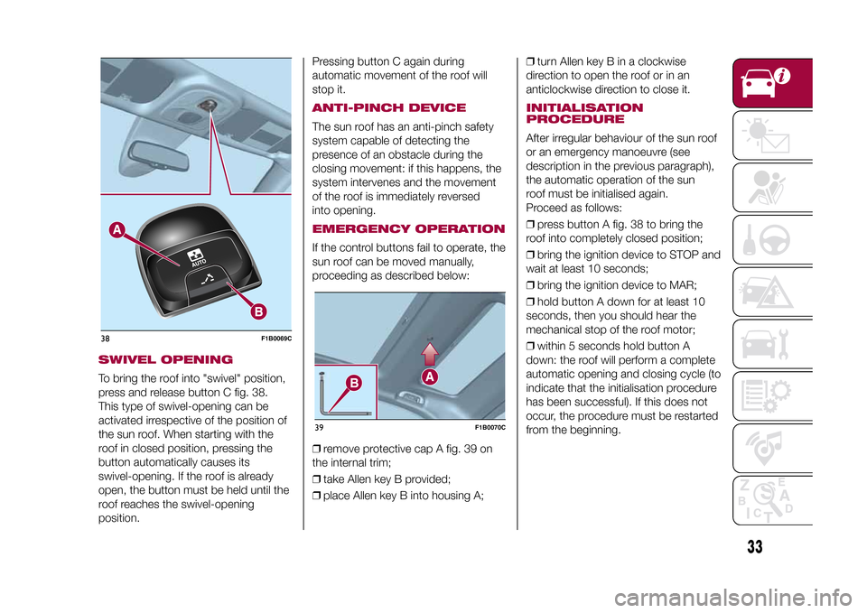
SWIVEL OPENINGTo bring the roof into "swivel" position,
press and release button C fig. 38.
This type of swivel-opening can be
activated irrespective of the position of
the sun roof. When starting with the
roof in closed position, pressing the
button automatically causes its
swivel-opening. If the roof is already
open, the button must be held until the
roof reaches the swivel-opening
position.Pressing button C again during
automatic movement of the roof will
stop it.
ANTI-PINCH DEVICEThe sun roof has an anti-pinch safety
system capable of detecting the
presence of an obstacle during the
closing movement: if this happens, the
system intervenes and the movement
of the roof is immediately reversed
into opening.EMERGENCY OPERATIONIf the control buttons fail to operate, the
sun roof can be moved manually,
proceeding as described below:
❒remove protective cap A fig. 39 on
the internal trim;
❒take Allen key B provided;
❒place Allen key B into housing A;❒turn Allen key B in a clockwise
direction to open the roof or in an
anticlockwise direction to close it.
INITIALISATION
PROCEDUREAfter irregular behaviour of the sun roof
or an emergency manoeuvre (see
description in the previous paragraph),
the automatic operation of the sun
roof must be initialised again.
Proceed as follows:
❒press button A fig. 38 to bring the
roof into completely closed position;
❒bring the ignition device to STOP and
wait at least 10 seconds;
❒bring the ignition device to MAR;
❒hold button A down for at least 10
seconds, then you should hear the
mechanical stop of the roof motor;
❒within 5 seconds hold button A
down: the roof will perform a complete
automatic opening and closing cycle (to
indicate that the initialisation procedure
has been successful). If this does not
occur, the procedure must be restarted
from the beginning.
38
F1B0069C
39
F1B0070C
33
15-12-2014 8:23 Pagina 33
Page 44 of 240

MAIN MENUThe Menu includes the following items:
❒TRIP
❒MOOD SELECTOR/GSI
❒VEHICLE INFO
❒DRIVER ASSIST
❒AUDIO
❒PHONE
❒NAVIGATION
❒ALERTS
❒VEHICLE SETUPVehicle setup (Change vehicle
settings)This menu item allows you to change
the settings for:
❒"Display";
❒"Units";
❒"Clock & Date";
❒"Security"
❒"Safety & Assistance";
❒"Lights";
❒"Doors & Locks".DisplayBy selecting item "Display" you can
access the settings/information
regarding: "Language", "See phone",
"See navigation", "Trip B automatic
reset", "Mood Selector repetition".
"Units"Select item "Units" to choose the unit of
measurement between: "Imperial",
"Metric", "Custom"."Clock & Date"Select item "Clock & Date" to make the
following adjustments: "Set time",
"Time format", Set date"."Security"Select item "Security" to make the
following adjustments: "Passenger
AIRBAG", "Speed beep", "Seat belt
buzzer", "Hill Hold Control".
"Passenger AIRBAG" adjustment allows
you to activate/deactivate the
passenger airbag:
❒Passenger's protection active: the
ONLED comes on constantly in
the instrument panel dashboard.
❒Passenger's protection not
active: the
OFFLED comes on
constantly in the instrument panel
dashboard.
"Safety & Assistance"For possible adjustments see the
Uconnect™paragraph in the
dedicated chapter.
"Lights"Select item "Lights" to make the
following adjustments: "Ambient
lighting", "Headlight sensor", "Follow
me", "Headlights while opening", "High
Beams Auto Dim", "Daytime Lights",
"Cornering lights"."Doors & Locks"Select item "Doors & Locks" to make
the following adjustments: "Autoclose",
"Auto unlock on exit", "Flash Lights
w/Lock", "Horn with Lock", "Horn
w/Remote Start", "Remote Unlock",
"Door Unlock" (versions with Keyless
Entry), "Keyless Entry".
42
KNOWING THE INSTRUMENT PANEL
15-12-2014 8:23 Pagina 42
Page 113 of 240
"Auto" MODEThis mode is aimed at comfort and
safety in normal grip and driving
conditions. On 4x4 versions, this mode
also reduces fuel consumption, since
it automatically disconnects the
transmission from the rear wheels if the
road and driving conditions allow it, in
addition to changing drive torque
distribution between the front and rear
axles.ActivationStarting from the active "Traction/All
Weather" mode, turn the ring nut
anticlockwise, keeping it in this position
for at least half a second, and in any
case until the relevant LED turns on,
and the selected mode is shown on the
display. The LED for the previously set
mode will simultaneously turn off. Upon
release, the ring nut will return to the
central position.
Starting from the active "Sport" mode,
turn the ring nut clockwise, keeping it in
this position for at least half a second,
and in any case until the relevant LED
turns on, and the selected mode is
shown on the display. The LED for the
previously set mode will simultaneously
turn off. Upon release, the ring nut will
return to the central position.
"Traction"/"All Weather" MODEIt is a driving mode for safety in poor
vehicle grip conditions (wet/slippery
road surface, rain, snow). On the 4x4
versions use is also recommended
on unsurfaced roads or off-road.ActivationStarting from the active "Auto" mode,
turn the ring nut clockwise, keeping it in
this position for at least half a second,
and in any case until the relevant LED
turns on, and the selected mode is
shown on the display. The LED for the
previously set mode will simultaneously
turn off. Upon release, the ring nut will
return to the central position.
Starting from the active "Sport" mode,
turn the ring nut anticlockwise, keeping
it in this position for at least half a
second, and in any case until the
relevant LED turns on, and the selected
mode is shown on the display. The
LED for the previously set mode will
simultaneously turn off. Upon release,
the ring nut will return to the central
position.
"Sport" MODEIt is the mode that emphasises the
pleasure of sport driving; it increases
fuel consumption however. Traction
is optimised on 4x4 versions, allowing
the vehicle road-hold performance
to be improved, even on bends.ActivationStarting from the active "Auto" mode,
turn the ring nut anticlockwise, keeping
it in this position for at least half a
second, and in any case until the
relevant LED turns on, and the selected
mode is shown on the display. The
LED for the previously set mode will
simultaneously turn off. Upon release,
the ring nut will return to the central
position.
Starting from the active "Traction/All
Weather" mode, turn the ring nut
clockwise, keeping it in this position for
at least half a second, and in any case
until the relevant LED turns on, and
the selected mode is shown on the
display. The LED for the previously set
mode will simultaneously turn off. Upon
release, the ring nut will return to the
central position.
111
15-12-2014 8:23 Pagina 111
Page 125 of 240
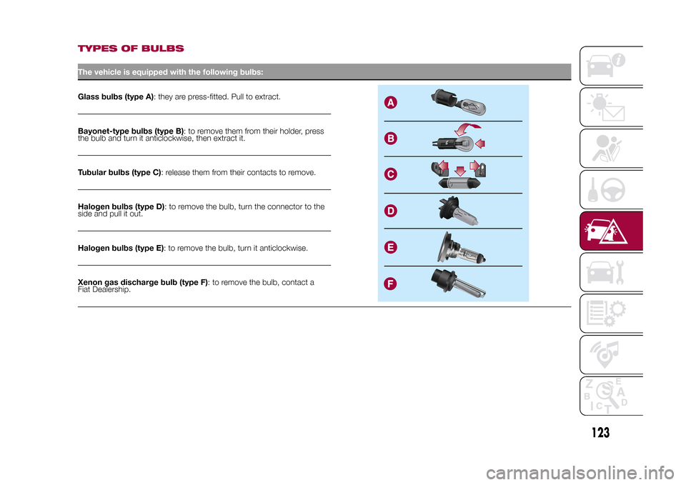
TYPES OF BULBSThe vehicle is equipped with the following bulbs:Glass bulbs (type A): they are press-fitted. Pull to extract.Bayonet-type bulbs (type B): to remove them from their holder, press
the bulb and turn it anticlockwise, then extract it.
Tubular bulbs (type C): release them from their contacts to remove.
Halogen bulbs (type D): to remove the bulb, turn the connector to the
side and pull it out.
Halogen bulbs (type E): to remove the bulb, turn it anticlockwise.
Xenon gas discharge bulb (type F): to remove the bulb, contact a
Fiat Dealership.
123
15-12-2014 8:23 Pagina 123
Page 127 of 240
REPLACING AN
EXTERNAL BULB
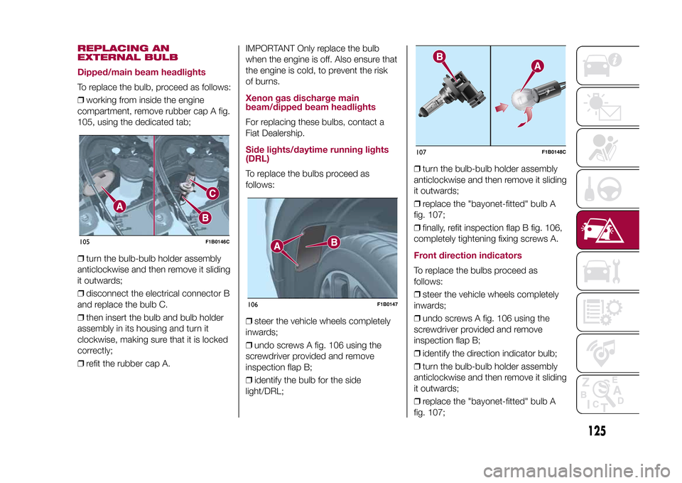
Dipped/main beam headlightsTo replace the bulb, proceed as follows:
❒working from inside the engine
compartment, remove rubber cap A fig.
105, using the dedicated tab;
❒turn the bulb-bulb holder assembly
anticlockwise and then remove it sliding
it outwards;
❒disconnect the electrical connector B
and replace the bulb C.
❒then insert the bulb and bulb holder
assembly in its housing and turn it
clockwise, making sure that it is locked
correctly;
❒refit the rubber cap A.IMPORTANT Only replace the bulb
when the engine is off. Also ensure that
the engine is cold, to prevent the risk
of burns.
Xenon gas discharge main
beam/dipped beam headlightsFor replacing these bulbs, contact a
Fiat Dealership.Side lights/daytime running lights
(DRL)To replace the bulbs proceed as
follows:
❒steer the vehicle wheels completely
inwards;
❒undo screws A fig. 106 using the
screwdriver provided and remove
inspection flap B;
❒identify the bulb for the side
light/DRL;❒turn the bulb-bulb holder assembly
anticlockwise and then remove it sliding
it outwards;
❒replace the "bayonet-fitted" bulb A
fig. 107;
❒finally, refit inspection flap B fig. 106,
completely tightening fixing screws A.
Front direction indicatorsTo replace the bulbs proceed as
follows:
❒steer the vehicle wheels completely
inwards;
❒undo screws A fig. 106 using the
screwdriver provided and remove
inspection flap B;
❒identify the direction indicator bulb;
❒turn the bulb-bulb holder assembly
anticlockwise and then remove it sliding
it outwards;
❒replace the "bayonet-fitted" bulb A
fig. 107;
105
F1B0146C
106
F1B0147
107
F1B0148C
125
15-12-2014 8:23 Pagina 125
Page 128 of 240
❒finally, refit inspection flap B fig. 106,
completely tightening fixing screws A.Fog lightsTo replace the bulbs proceed as
follows:
❒steer the vehicle wheels completely
inwards;
❒undo screws A fig. 106 using the
screwdriver provided and remove
inspection flap B;
❒identify the fog light bulb;
❒turn the bulb-bulb holder assembly
anticlockwise and then remove it sliding
it outwards;
❒disconnect the electrical connector;
❒replace the bulb-bulb holder
assembly B fig. 107.
❒reconnect the electrical connector to
the new bulb-bulb holder assembly,
then fit it ensuring that it locks correctly;
❒fit the assembly turning it clockwise,
ensuring that it locks correctly;
❒finally, refit inspection flap B fig. 106,
completely tightening fixing screws A.Side direction indicatorsIMPORTANT The procedure is only
described by way of illustration. It
is advisable to contact a Fiat Dealership
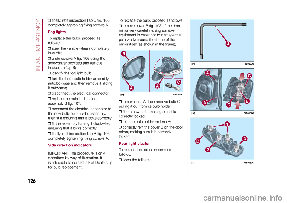
for bulb replacement.To replace the bulb, proceed as follows:
❒remove cover B fig. 108 of the door
mirror very carefully (using suitable
equipment in order not to damage the
paintwork) around the frame of the
mirror itself (as shown in the figure);
❒remove lens A, then remove bulb C
pulling it out from its bulb holder.
❒fit the new bulb, making sure it is
correctly locked;
❒refit the bulb holder on lens A;
❒correctly refit the cover B on the door
mirror, making sure it is correctly
locked.
Rear light clusterTo replace the bulbs proceed as
follows:
❒open the tailgate;108
F1B0149C
109
F1B0022C
110
F1B0151C
111
F1B0152C
126
IN AN EMERGENCY
15-12-2014 8:23 Pagina 126
Page 129 of 240
❒use the wrench A fig. 109 supplied
with the vehicle (located inside the case
with the on-board documentation),
undo the two screws A fig. 110, then
release the light cluster from the
relevant pin fastenings, pulling
cautiously;
❒disconnect the central connector B,
then undo the two screws C;
❒release the tabs indicated by the
arrows and extract the bulb holder
assembly D fig. 111;
❒identify the bulb to be replaced (1
Side/Stop - 2 Direction indicator -
3 Rear fog light or Reverse);
❒all bulbs are "bayonet-fitted";
therefore they must be lightly pressed
and simultaneously turned to be
replaced: anticlockwise for extraction,
clockwise for fitting;
❒correctly refit the bulb holder
assembly D in the light casing; stop
when you hear that the tabs click into
place;
❒tighten the two screws C fig. 110 and
reconnect the central connector B;
❒refit the lens unit, fully tightening the
two screws A;
❒reclose the tailgate.
3rd
brake lights
The 3
rd
brake lights are LED-based. For
their replacement, contact a Fiat
Dealership.
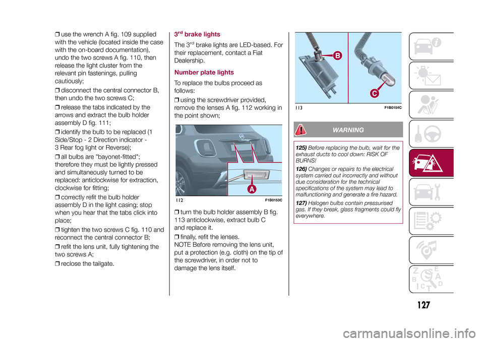
Number plate lightsTo replace the bulbs proceed as
follows:
❒using the screwdriver provided,
remove the lenses A fig. 112 working in
the point shown;
❒turn the bulb holder assembly B fig.
113 anticlockwise, extract bulb C
and replace it.
❒finally, refit the lenses.
NOTE Before removing the lens unit,
put a protection (e.g. cloth) on the tip of
the screwdriver, in order not to
damage the lens itself.
WARNING
125)Before replacing the bulb, wait for the
exhaust ducts to cool down: RISK OF
BURNS!
126)Changes or repairs to the electrical
system carried out incorrectly and without
due consideration for the technical
specifications of the system may lead to
malfunctioning and generate a fire hazard.
127)Halogen bulbs contain pressurised
gas. If they break, glass fragments could fly
everywhere.
112
F1B0153C
113
F1B0154C
127
15-12-2014 8:23 Pagina 127