2015 FIAT 500X warning
[x] Cancel search: warningPage 122 of 240

123)Do not get close to the filler of the
tank with naked flames or lit cigarettes: risk
of fire. Do not get too close to the filler
with your face, in order not to inhale
harmful vapours.
124)Do not use a mobile phone near the
fuel pump: risk of fire.
WARNING
50)Vehicles with a diesel engine must only
be filled with diesel fuel for motor vehicles,
in compliance with European Standard
EN 590. The use of other products or
mixtures may damage the engine beyond
repair and consequently invalidate the
warranty, due to the damage caused. If
you accidentally refuel with another type of
fuel, do not start the engine, and drain
the tank. If the engine has run, even for a
very short time, you will need to have
the entire fuel supply system emptied in
addition to the tank.
120
STARTING AND DRIVING
15-12-2014 8:23 Pagina 120
Page 123 of 240

IN AN EMERGENCY
A punctured tyre or a burnt-out bulb?
At times, a problem may interfere
with our journey.
The pages on emergencies can help
you to deal with critical situations
independently and with calm.
In an emergency we recommend that
you call the freephone number found in
the Warranty Booklet.
It is also possible to call the national or
international universal freephone
number to search for the nearest Fiat
Dealership.HAZARD WARNING LIGHTS...........122
BULB REPLACEMENT....................122
REPLACING FUSES........................128
CHANGING A WHEEL ....................133
FIX&GO AUTOMATIC KIT ................136
EMERGENCY STARTING ................138
FUEL CUT-OFF SYSTEM ................140
AUTOMATIC TRANSMISSION
GEAR LEVER UNLOCKING.............140
TOWING THE VEHICLE ..................142
121
15-12-2014 8:23 Pagina 121
Page 124 of 240

HAZARD WARNING
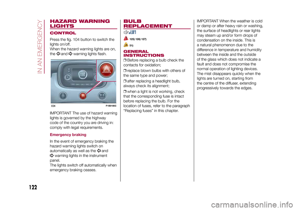
LIGHTSCONTROLPress the fig. 104 button to switch the
lights on/off.
When the hazard warning lights are on,
the
and
warning lights flash.
IMPORTANT The use of hazard warning
lights is governed by the highway
code of the country you are driving in:
comply with legal requirements.
Emergency brakingIn the event of emergency braking the
hazard warning lights switch on
automatically as well as the
and
warning lights in the instrument
panel.
The lights switch off automatically when
emergency braking ceases.
BULB
REPLACEMENT
125) 126) 127)51)
GENERAL
INSTRUCTIONS❒Before replacing a bulb check the
contacts for oxidation;
❒replace blown bulbs with others of
the same type and power;
❒after replacing a headlight bulb,
always check its alignment;
❒when a light is not working, check
that the corresponding fuse is intact
before replacing the bulb. For the
location of fuses, refer to the paragraph
“Replacing fuses” in this chapter.IMPORTANT When the weather is cold
or damp or after heavy rain or washing,
the surface of headlights or rear lights
may steam up and/or form drops of
condensation on the inside. This is
a natural phenomenon due to the
difference in temperature and humidity
between the inside and the outside
of the glass which does not indicate a
fault and does not compromise the
normal operation of lighting devices.
The mist disappears quickly when the
lights are turned on, starting from
the centre of the diffuser, extending
progressively towards the edges.
104
F1B0185C
122
IN AN EMERGENCY
15-12-2014 8:23 Pagina 122
Page 129 of 240

❒use the wrench A fig. 109 supplied
with the vehicle (located inside the case
with the on-board documentation),
undo the two screws A fig. 110, then
release the light cluster from the
relevant pin fastenings, pulling
cautiously;
❒disconnect the central connector B,
then undo the two screws C;
❒release the tabs indicated by the
arrows and extract the bulb holder
assembly D fig. 111;
❒identify the bulb to be replaced (1
Side/Stop - 2 Direction indicator -
3 Rear fog light or Reverse);
❒all bulbs are "bayonet-fitted";
therefore they must be lightly pressed
and simultaneously turned to be
replaced: anticlockwise for extraction,
clockwise for fitting;
❒correctly refit the bulb holder
assembly D in the light casing; stop
when you hear that the tabs click into
place;
❒tighten the two screws C fig. 110 and
reconnect the central connector B;
❒refit the lens unit, fully tightening the
two screws A;
❒reclose the tailgate.
3rd
brake lights
The 3
rd
brake lights are LED-based. For
their replacement, contact a Fiat
Dealership.
Number plate lightsTo replace the bulbs proceed as
follows:
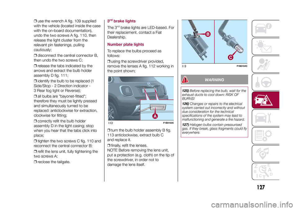
❒using the screwdriver provided,
remove the lenses A fig. 112 working in
the point shown;
❒turn the bulb holder assembly B fig.
113 anticlockwise, extract bulb C
and replace it.
❒finally, refit the lenses.
NOTE Before removing the lens unit,
put a protection (e.g. cloth) on the tip of
the screwdriver, in order not to
damage the lens itself.
WARNING
125)Before replacing the bulb, wait for the
exhaust ducts to cool down: RISK OF
BURNS!
126)Changes or repairs to the electrical
system carried out incorrectly and without
due consideration for the technical
specifications of the system may lead to
malfunctioning and generate a fire hazard.
127)Halogen bulbs contain pressurised
gas. If they break, glass fragments could fly
everywhere.
112
F1B0153C
113
F1B0154C
127
15-12-2014 8:23 Pagina 127
Page 130 of 240

WARNING
51)Halogen bulbs must be handled by
holding the metallic part only. Touching the
transparent part of the bulb with your
fingers may reduce the intensity of the
emitted light and even reduce the lifespan
of the bulb. In the case of accidental
contact, rub the lamp with a cloth and
alcohol and leave to dry.
REPLACING FUSESINTRODUCTION
128) 129) 130) 131)52) 53)
Fuses protect the electrical system:
they intervene (blow) in the event of a
failure or improper action on the
system.Fuse extracting pliersTo replace a fuse, use the pliers hooked
to the side of the engine compartment
fuse box cover (see fig. 114).
The pliers have two different ends,
specifically designed to remove the
different types of fuses present in the
vehicle.
To take out the pliers, grab them from
the upper tabs, press and pull upwards.
After being used, the pliers should be
positioned properly in their housing,
grabbing them from the upper tabs,
pressing and pushing them until a click
is heard.
FUSE LOCATIONFuses are grouped together in the fuse
boxes located in the engine
compartment, under the dashboard
and inside the boot.ENGINE COMPARTMENT
FUSE BOXThe fuse box is located by the side of
the battery fig. 115.
To access the fuses, proceed as
follows:
❒fully tighten screw A fig. 116, using
the screwdriver provided;
❒at the same time slowly rotate the
screw anticlockwise, until resistance is
encountered (do not overtighten);
❒slowly release the screw;
❒opening is indicated by the entire
screw head coming out of its housing;114
F1B0187C
128
IN AN EMERGENCY
15-12-2014 8:23 Pagina 128
Page 134 of 240

BOOT FUSE BOXNOTE The configuration of the boot may vary in accordance with the equipment on the vehicle.Fuse box BUSERSFUSE AMPEREHI-FI system F2 20
Electric sun roof F3 20
Front seat electric lumbar adjustment (driver guide) F4 7.5
Electric front seat adjustment (driver side) F5 30
Electric front seat adjustment (driver side and passenger side) F6 7.5
Electric front seat lumbar adjustment (driver side and passenger
side)F7 30
WARNING
128)If the fuse blows again contact a Fiat Dealership.
129)Never replace a fuse with another with a higher amp rating; DANGER OF FIRE
130)If a fuse NOT described on this page and on the previous one blows, contact a Fiat Dealership.
131)Before replacing a fuse, make sure that the ignition device has been taken to STOP, that the ignition key, if mechanical, has been
removed and that all the other devices are switched off and/or deactivated.
WARNING
52)Never replace a blown fuse with metal wires or other material.
53)If it is necessary to wash the engine compartment, take care not to directly hit the fuse box and the window wiper motor with the water
jet.
132
IN AN EMERGENCY
15-12-2014 8:23 Pagina 132
Page 135 of 240

CHANGING A WHEELJACKPlease note that:
❒the weight of the jack is 2.8 kg;
❒The jack requires no adjustment;
❒the jack cannot be repaired and in
the event of a fault it must be replaced
by another original one;
❒No tool other than its cranking device
may be fitted on the jack.CHANGING PROCEDURE
132) 133) 134) 135) 136) 137) 138) 139)
Proceed as follows:
❒stop the vehicle in a position that is
not dangerous for oncoming traffic
where you can change the wheel safely.
The ground should be flat if possible,
and sufficiently firm;
❒stop the engine, engage the hazard
warning lights and the electric parking
brake;
❒engage first gear or reverse or, for
versions with automatic transmission,
move the lever to position P (Park);
❒wear the reflective safety jacket
(compulsory by law in certain countries)
before getting out of the vehicle;❒open the boot and position the
reconfigurable load platform in
an inclined position (see "Boot" in the
"Knowing your vehicle" chapter);
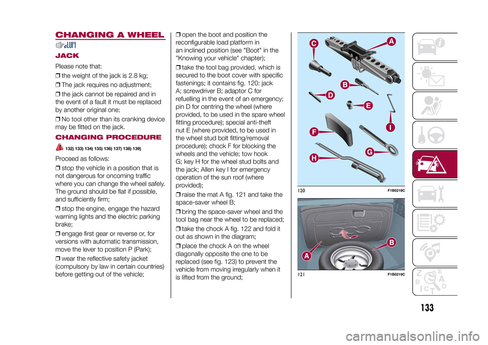
❒take the tool bag provided, which is
secured to the boot cover with specific
fastenings; it contains fig. 120: jack
A; screwdriver B; adaptor C for
refuelling in the event of an emergency;
pin D for centring the wheel (where
provided, to be used in the spare wheel
fitting procedure); special anti-theft
nut E (where provided, to be used in
the wheel stud bolt fitting/removal
procedure); chock F for blocking the
wheels and the vehicle; tow hook
G; key H for the wheel stud bolts and
the jack; Allen key I for emergency
operation of the sun roof (where
provided);
❒raise the mat A fig. 121 and take the
space-saver wheel B;
❒bring the space-saver wheel and the
tool bag near the wheel to be replaced;
❒take the chock A fig. 122 and fold it
out as shown in the diagram;
❒place the chock A on the wheel
diagonally opposite the one to be
replaced (see fig. 123) to prevent the
vehicle from moving irregularly when it
is lifted from the ground;
120
F1B0218C
121
F1B0219C
133
15-12-2014 8:23 Pagina 133
Page 137 of 240

❒place the punctured tyre in the boot
upside down (with the outer part facing
upwards), then reposition the jack
and the used tools;
❒reposition the boot mat then
reposition the reconfigurable load
platform in a flat position (see "Boot" in
the "Knowing your vehicle" chapter).
Restore the standard wheel as soon as
possible, because, once placed in the
associated compartment, the boot load
platform is rendered uneven as the
standard wheel is larger than the
space-saver wheel.
WARNING
132)If left in the passenger compartment,
the punctured wheel and jack constitute
a serious risk to the safety of occupants in
the event of accidents or sharp braking.
Therefore, always place both the jack and
punctured wheel in the dedicated housing
in the boot.
133)It is extremely dangerous to attempt
to change a wheel on the side of the
vehicle next to the driving lane: make sure
that the vehicle is at a sufficient distance
from the road, to avoid being run over.
134)Alert other drivers that the vehicle is
stationary in compliance with local
regulations: hazard warning lights, warning
triangle, etc. Any passengers on board
should leave the vehicle, especially if it is
heavily laden. Passengers should stay
away from on-coming traffic while the
wheel is being changed. For safety
reasons, always block the wheels with the
chocks provided.135)The vehicle's driving characteristics
will be modified with the space-saver wheel
fitted. Avoid violent acceleration and
braking, abrupt steering and fast cornering.
The overall duration of the space-saver
wheel is about 3000 km, after which the
relevant tyre must be replaced with another
one of the same type. Never install a
standard tyre on a rim that is designed for
use with a space-saver wheel. Have the
wheel repaired and refitted as soon as
possible. Using two or more space-saver
wheels at the same time is forbidden.
Do not grease the threads of the stud bolts
before fitting them: they might slip out
when driving!
136)The space-saver wheel is specific to
your vehicle: do not use it on other models,
or use the space-saver wheel of other
models on your vehicle. The space-saver
wheel must only be used in the event of an
emergency. It must only be used for the
distance necessary to reach a service point
and the vehicle speed must not exceed
80 km/h. The space-saver wheel has
an orange label that summarises the main
cautions for use and limitations. Never
remove or cover the sticker.
126
F1B0225C
135
15-12-2014 8:23 Pagina 135