Page 163 of 426
ELECTRONIC VEHICLE INFORMATION CENTER
(EVIC)
The Electronic Vehicle Information Center (EVIC) fea-
tures a driver-interactive display that is located in the
instrument cluster.
The EVIC consists of the following:
•System Status
•Vehicle Information Warning Message Displays
•Personal Settings (Customer-Programmable Features)
•Outside Temperature Display
•Trip Computer Functions
•Tire Pressure Monitoring Display
Electronic Vehicle Information Center (EVIC) Display
4
UNDERSTANDING YOUR INSTRUMENT PANEL 161
Page 164 of 426
EVIC Displays
1. Red Telltales (Left Bank)
•Hood Ajar
•Low Oil Pressure
•Electronic Throttle Control
•Door Ajar
•Speed Limiter — If Equipped
2. Amber Telltales
•Ice Risk
•Fuel Cut Off
•Fuel Cut Off Failed
•Hill Holder Failed
•Oil Change Request
•Check Lights
•Vehicle Lock
3. Electronic Speed Control Active
4. Amber Telltales
•Generic Warning Light
•Glow Plug Light
•Park Sensor Failed
•Stop Lamp Failed
Instrument Cluster
162 UNDERSTANDING YOUR INSTRUMENT PANEL
Page 168 of 426
after a single chime has sounded to indicate the next
scheduled oil change interval. The engine oil change
indicator system is duty cycle based, which means the
engine oil change interval may fluctuate, dependent
upon your personal driving style.
Unless reset, this message will continue to display each
time you turn the ignition switch to the ON/RUN
position. To turn off the message temporarily, push and
release theMENUbutton. To reset the oil change indica-
tor system (after performing the scheduled maintenance),
refer to the following procedure.
1. Turn the ignition switch to the ON position. (do not
start the engine.)
2. Fully push the accelerator pedal slowly, three times
within 10 seconds.
3. Turn the ignition switch to the OFF/LOCK position.
NOTE:If the indicator message illuminates when you
start the vehicle, the oil change indicator system did not
reset. If necessary, repeat this procedure.
Trip Computer
The Trip Computer is located in the instrument cluster. It
features a driver-interactive display (displays informa-
tion such as trip information, range, fuel consumption,
average speed, and travel time).
Trip Button
TheTRIPbutton, located on the right steering column
stalk, can be used to display and to reset the previously
described values.
•A short button push displays the different values.
•A long button push resets the system and then starts a
new trip.
166 UNDERSTANDING YOUR INSTRUMENT PANEL
Page 176 of 426
•CD audio, CD MP3: track number.
To activate (On) or to deactivate (Off) the sound system
info displaying, proceed as follows:
1. Briefly push and release theMENUbutton. Push and
release the UPor Downbutton to highlight
See Radio and push and release theMENUbutton.
2. Push and release the UPor DOWNbutton for
setting.
3. Briefly push and release theMENUbutton to go back
to the menu screen, or push and hold theMENU
button (approximately one second) to go back to the
main screen without storing the settings.
If the radio has BLUE&ME™, refer to the appropriate
“BLUE&ME™ Radio Supplement” for further informa-
tion.
Speed Display
When this function is activated the cluster will display
the vehicle speed (MPH or km/h).
To activate (On) or to deactivate (Off) the speed display
feature, proceed as follows:
1. Briefly push and release theMENUbutton. Push and
release the UPor DOWNbutton to highlight
Speed Display. Push and release the MENU button
to enter the Speed DisplayMENU.
2. Push and release the UPor DOWNbutton to
select display deactivation “Off”, “MPH” or
“km/h.”
3. Briefly push and release theMENUbutton to go back
to the menu screen, or push and hold theMENU
button (approximately one second) to go back to the
main screen.
174 UNDERSTANDING YOUR INSTRUMENT PANEL
Page 181 of 426
3. Push and release the UPor DOWNbutton for
setting.
4. Briefly push and release theMENUbutton to go back
to the menu screen, or push and hold the button
(approximately one second) to go back to the main
screen without storing the settings.
GSI (Gear Shift Indicator)
This function may be used to set the Gear Shift Indicator
in two submenus: “Fuel Econ On” and “Fuel Econ Off.”
•Fuel Econ On – turns on a fuel economy upshift light
in the instrument cluster, for optimum fuel economy,
when operating in base driving mode.
•Fuel Econ Off – the fuel economy upshift light is
disabled.
To set the required unit, proceed as follows:
1. Briefly push and release theMENUbutton to display
the two sub-menus.
2. Push and release the UPor DOWNbutton to
navigate the two sub-menus.
3. Select the required sub-menu and then briefly push
and release theMENUbutton.
4. Push and release the UPor DOWNbutton for
setting.
5. Briefly push and release theMENUbutton to return to
the sub-menu.
When you have made the required settings, briefly push
and release theMENUbutton to go back to the sub-menu
screen, or push and hold theMENUbutton (approxi-
mately one second) to go back to the main screen without
storing the settings.
4
UNDERSTANDING YOUR INSTRUMENT PANEL 179
Page 230 of 426

Turn the ignition switch to the AVV/ACC (START)
position and release it when the engine starts. If the
engine fails to start within 10 seconds, turn the ignition
switch to the STOP (OFF/LOCK) position, wait 10 to
15 seconds, then repeat the “Normal Starting” procedure.
Cold Weather Operation
To prevent possible engine damage while starting at low
temperatures, this vehicle will inhibit engine cranking
when the ambient temperature is less than –22° F (–30° C)
and the oil temperature sensor reading indicates an
engine block heater has not been used. An externally-
powered electric engine block heater is available as
optional equipment or from your authorized dealer.
The message “plug in engine heater” will be displayed in
the instrument cluster when the ambient temperature is
below 5° F (–15° C) at the time the engine is shut off as a
reminder to avoid possible crank delays at the next cold
start.
CAUTION!
Use of the recommended SAE 5W-40 synthetic en-
gine oil and adhering to the prescribed oil change
intervals is important to prevent engine damage and
ensure satisfactory starting in cold conditions.
Extended Park Starting
NOTE:Extended Park condition occurs when the vehicle
has not been started or driven for at least 35 days.
1. Install a battery charger or jumper cables to the battery
to ensure a full battery charge during the crank cycle.
2. Cycle the ignition in the START position and release it
when the engine starts.
228 STARTING AND OPERATING
Page 237 of 426
Key Ignition Park Interlock
This vehicle is equipped with a Key Ignition Park Inter-
lock which requires the transmission to be in PARK
before the ignition switch can be turned to the LOCK/
OFF (key removal) position. The key can only be re-
moved from the ignition when the ignition is in the
LOCK/OFF position, and once removed, the transmis-
sion is locked in PARK.
Brake/Transmission Shift Interlock System
This vehicle is equipped with a Brake Transmission Shift
Interlock System (BTSI) that holds the shift lever in PARK
unless the brakes are applied. To shift the transmission
out of PARK, the ignition switch must be turned to the
ON/RUN position (engine running or not) and the brake
pedal must be pressed.
Six-Speed Automatic Transmission
The transmission gear position display (located in the
instrument cluster) indicates the transmission gear range.
You must press the brake pedal to move the shift lever
out of PARK (Refer to “Brake/Transmission Shift Inter-
lock System” in this section). To drive, move the shift
lever from PARK or NEUTRAL to the DRIVE position.
The electronically-controlled transmission provides a
precise shift schedule. The transmission electronics are
self-calibrating; therefore, the first few shifts on a new
vehicle may be somewhat abrupt. This is a normal
condition, and precision shifts will develop within a few
hundred miles (kilometers).
5
STARTING AND OPERATING 235
Page 238 of 426
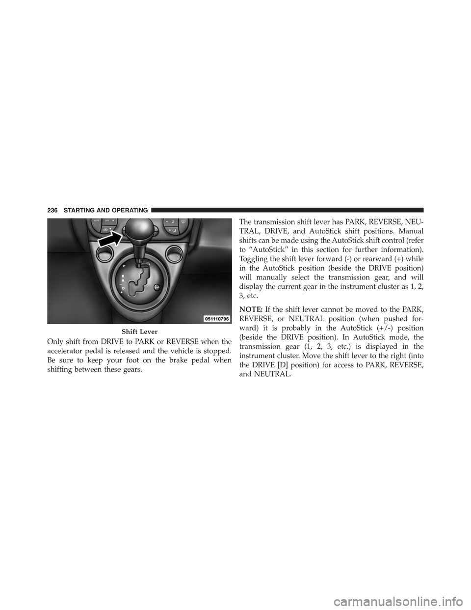
Only shift from DRIVE to PARK or REVERSE when the
accelerator pedal is released and the vehicle is stopped.
Be sure to keep your foot on the brake pedal when
shifting between these gears.
The transmission shift lever has PARK, REVERSE, NEU-
TRAL, DRIVE, and AutoStick shift positions. Manual
shifts can be made using the AutoStick shift control (refer
to “AutoStick” in this section for further information).
Toggling the shift lever forward (-) or rearward (+) while
in the AutoStick position (beside the DRIVE position)
will manually select the transmission gear, and will
display the current gear in the instrument cluster as 1, 2,
3, etc.
NOTE:If the shift lever cannot be moved to the PARK,
REVERSE, or NEUTRAL position (when pushed for-
ward) it is probably in the AutoStick (+/-) position
(beside the DRIVE position). In AutoStick mode, the
transmission gear (1, 2, 3, etc.) is displayed in the
instrument cluster. Move the shift lever to the right (into
the DRIVE [D] position) for access to PARK, REVERSE,
and NEUTRAL.
Shift Lever
236 STARTING AND OPERATING