2015 DODGE GRAND CARAVAN instrument cluster
[x] Cancel search: instrument clusterPage 3 of 164

INTRODUCTION/WELCOME
WELCOME FROM CHRYSLERGROUP LLC..................3
CONTROLS AT A GLANCE
DRIVER COCKPIT...............6INSTRUMENT CLUSTER...........8
GETTING STARTED
KEY FOB . . . . . . . . . . . . . . . . . . . 10REMOTE START . . . . . . . . . . . . . . . 11KEYLESS ENTER-N-GO™.........12VEHICLE SECURITY ALARM........16SEAT BELT SYSTEMS............17SUPPLEMENTAL RESTRAINT SYSTEM(SRS) — AIR BAGS.............18CHILD RESTRAINTS............21HEAD RESTRAINTS.............26FRONT SEATS................28REAR SEATS.................31HEATED SEATS . . . . . . . . . . . . . . . 36HEATED STEERING WHEEL........37TILT/TELESCOPING STEERINGCOLUMN...................38
OPERATING YOUR VEHICLE
ENGINE BREAK-INRECOMMENDATIONS............39TURN SIGNAL/WIPER/WASHER/HIGHBEAM LEVER.................40HEADLIGHT SWITCH AND HALO LIGHTSWITCH....................42ELECTRONIC SPEED CONTROL......43ELECTRONIC RANGE SELECTION (ERS) . . 45FUEL ECONOMY (ECON) MODE......46MANUAL CLIMATE CONTROLS.......47THREE ZONE MANUAL CLIMATECONTROLS..................48THREE ZONE AUTOMATIC TEMPERATURECONTROLS (ATC)...............50PA R K S E N S E®REAR PARK ASSIST....52PA R K V I E W®REAR BACK-UP CAMERA . . 52BLIND SPOT MONITORING WITH REARCROSS PATH.................52POWER SLIDING SIDE DOORS.......53POWER LIFTGATE..............53POWER SUNROOF..............54WIND BUFFETING..............55
ELECTRONICS
YOUR VEHICLE'S SOUND SYSTEM....56Uconnect®130 . . . . . . . . . . . . . . . . 58Uconnect®130 WITH SiriusXM SATELLITERADIO.....................60Uconnect®430/430N............63
SiriusXM SATELLITE RADIO/TRAVELLINK......................73STEERING WHEEL AUDIO CONTROLS . . 77iPod®/USB/MP3 CONTROL.........77Uconnect®PHONE..............78Uconnect®VOICE COMMAND........81Bluetooth®STREAMING AUDIO......84VIDEO ENTERTAINMENT SYSTEM(VES™)....................84ELECTRONIC VEHICLE INFORMATIONCENTER (EVIC)................86PROGRAMMABLE FEATURES.......87UNIVERSAL GARAGE DOOR OPENER(HomeLink®).................89POWER INVERTER.............91POWER OUTLETS..............92
UTILITY
IN-FLOOR STORAGE — STOW'N GO®...94ROOF LUGGAGE RACK...........94TRAILER TOWING WEIGHTS (MAXIMUMTRAILER WEIGHT RATINGS)........95RECREATIONAL TOWING (BEHINDMOTORHOME, ETC.)............96
WHAT TO DO IN EMERGENCIES
ROADSIDE ASSISTANCE..........97INSTRUMENT CLUSTER WARNINGLIGHTS....................97INSTRUMENT CLUSTER INDICATORLIGHTS...................101IF YOUR ENGINE OVERHEATS......103TIRE SERVICE KIT.............103JACKING AND TIRE CHANGING.....110JUMP-STARTING..............122SHIFT LEVER OVERRIDE.........124TOWING A DISABLED VEHICLE.....124FREEING A STUCK VEHICLE.......125EVENT DATA RECORDER (EDR).....126
MAINTAINING YOUR VEHICLE
OPENING THE HOOD...........127ENGINE COMPARTMENT.........128FLUID CAPACITIES............130FLUIDS, LUBRICANTS AND GENUINEPA RT S . . . . . . . . . . . . . . . . . . . . 1 3 0MAINTENANCE PROCEDURES......132MAINTENANCE SCHEDULE.......132MAINTENANCE RECORD.........136FUSES....................137TIRE PRESSURES.............141SPARE TIRES — IF EQUIPPED.....142ADDING FUEL................144WHEEL AND WHEEL TRIM CARE....145REPLACEMENT BULBS..........146
TABLE OF CONTENTS
Page 8 of 164

DRIVER COCKPIT
1. Headlight Switch pg. 42
2. Electronic Vehicle Information Center (EVIC) Controls pg. 86
3. Turn Signal/Wiper/Washer/High Beams Lever (behind steering wheel) pg. 40
4. Instrument Cluster pg. 8
5. Electronic Vehicle Information Center (EVIC) Display
6. Speed Control pg. 43
7. Ignition
8. Shift Lever
9. Audio System (Touchscreen Radio Shown) pg. 56
10. Manual Climate Controls pg. 47
CONTROLS AT A GLANCE
6
Page 10 of 164

INSTRUMENT CLUSTER
1. Tachometer
2. Temperature Gauge
3. Electronic Vehicle Information Center (EVIC)
(See page 97 for more Instrument Cluster Warning Light information.)
CONTROLS AT A GLANCE
8
Page 11 of 164

4. Speedometer
5. Fuel Gauge
6. Fuel Filler Door Location
(See page 101 for more Instrument Cluster Indicator Light information.)
CONTROLS AT A GLANCE
9
Page 18 of 164

VEHICLE SECURITY ALARM
This Vehicle Security Alarm monitors the doors, liftgate, and ignition switch for unauthor-
ized operation.
When the alarm is activated, the interior switches for door locks are disabled. The Vehicle
Security Alarm provides both audio and visual signals repeatedly for three minutes. If the
disturbance is still present (driver's door, passenger door, other doors, ignition) after three
minutes, the parking lights and tail lights will flash for an additional 15 minutes.
To Arm:
•Lockthedoorusingeitherthepowerdoorlockswitch(onedoormustbeopen)orthe
LOCK button on the Remote Keyless Entry (RKE) transmitter (doors can be open or
closed), and close all doors.
The Vehicle Security Light in the instrument cluster will flash for 16 seconds. This shows
that the Vehicle Security Alarm is arming. During this period, if a door is opened, the
ignition is cycled to ON/RUN, or the power door locks are unlocked in any manner, the
Vehicle Security Alarm will automatically disarm.
NOTE:
•TheVehicleSecurityAlarmwillnotarmifyoulockthedoorswiththemanualdoorlock
plungers.
•Oncearmed,theVehicleSecurityAlarmdisablestheunlockswitchonthedriverdoor
trim panel and passenger door trim panel.
To Disarm The System:
•PushtheKeyFobUNLOCKbuttonorcycletheignitiontotheON/RUNposition.
The Vehicle Security Alarm is designed to protect your vehicle; however, you can create
conditions where the Vehicle Security Alarm will give you a false alarm. If one of the
previously described arming sequences has occurred, the Vehicle Security Alarm will arm
regardless of whether you are in the vehicle or not. If you remain in the vehicle and open
adoor,thealarmwillsound.Ifthisoccurs,disarmtheVehicleSecurityAlarm.
If the Vehicle Security Alarm is armed and the battery becomes disconnected the Vehicle
Security Alarm will remain armed when the battery is reconnected. The exterior lights will
flash, and the horn will sound. If this occurs, disarm the Vehicle Security Alarm.
GETTING STARTED
16
Page 45 of 164

ELECTRONIC SPEED CONTROL
The Electronic Speed Control switches are located on the steering wheel.
Cruise ON/OFF
•PushtheON/OFFbuttontoactivatethe
Speed Control.
NOTE:
CRUISEwill appear on the instrument
cluster to indicate the Speed Control is on.
•PushtheON/OFFbuttonasecondtime
to turn the system off.
SET
With the Speed Control on, push and re-
lease the SET – button to set a desired
speed.
Accel/Decel
To Increase Speed
When the Electronic Speed Control is set,
you can increase speed by pushing the RES
+button.
The speed increment shown is dependant on the chosen speed unit of U.S. (MPH) or
Metric (km/h):
U.S. Speed (MPH)
•PushingtheRES+button once will result in a 1 MPH increase in set speed. Each
subsequent tap of the button results in an increase of 1 MPH.
•Ifthebuttoniscontinuallypushed,thesetspeedwillcontinuetoincreaseuntilthe
button is released, then the new set speed will be established.
Metric Speed (km/h)
•PushingtheRES+button once will result in a 2 km/h increase in set speed. Each
subsequent tap of the button results in an increase of 2 km/h.
•Ifthebuttoniscontinuallypushed,thesetspeedwillcontinuetoincreaseuntilthe
button is released, then the new set speed will be established.
Electronic Speed Control Switches
1—PushOn/Off2—PushResume/Accel3—PushSet/Decel4—PushCancel
OPERATING YOUR VEHICLE
43
Page 54 of 164

PARKSENSE® REAR PARK ASSIST
If an object is detected behind the rear bumper while the vehicle is in REVERSE, a
warning will display in the instrument cluster and a tone will sound, (closer the object the
faster the tone) that changes speed depending on the distance of the object from the
bumper, will sound.
When the Instrument Cluster reads either “Clean Sensor” or “Blinded”, clean off the
bumper sensors to see if the condition is corrected.
PARKVIEW® REAR BACK-UP CAMERA
Yo u c a n s e e a n o n - s c r e e n i m a g e o f t h e r e a r o f y o u r v e h i c l e w h e n e v e r t h e s h i f t l e v e r i s p u t
into REVERSE. The ParkView®Rear Back-Up Camera image will be displayed on the radio
display screen, located on the center stack of the instrument panel.
If the radio display screen appears foggy, clean the camera lens located on the liftgate.
Refer to your Owner's Manual on the DVD for further details.
WARNING!
Drivers must be careful when backing up; even when using the ParkView®Rear
Back-Up Camera. Always check carefully behind your vehicle, and be sure to check for
pedestrians, animals, other vehicles, obstructions, or blind spots before backing up.
Yo u m u s t c o n t i n u e t o p a y a t t e n t i o n w h i l e b a c k i n g u p . F a i l u r e t o d o s o c a n r e s u l t i n
serious injury or death.
BLIND SPOT MONITORING WITH REAR CROSS PATH
The Blind Spot Monitoring (BSM) system uses two radar-based sensors, located inside the
rear bumper fascia, to detect Highway licensable vehicles (automobiles, trucks, motor-
cycles etc.) that enter the blind spot zones from the rear/front/side of the vehicle.
The Blind Spot Monitoring (BSM) system warning light, located in the outside mirrors, will
illuminate if a vehicle moves into a blind spot zone.
The BSM system can also be configured to sound an audible (chime) alert and mute the
radio to notify you of objects that have entered the detection zones.
Refer to your Owner's Manual on the DVD for further details.
OPERATING YOUR VEHICLE
52
Page 88 of 164

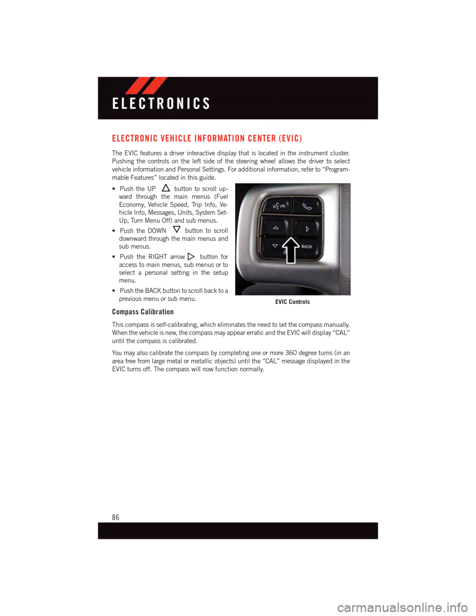
ELECTRONIC VEHICLE INFORMATION CENTER (EVIC)
The EVIC features a driver interactive display that is located in the instrument cluster.
Pushing the controls on the left side of the steering wheel allows the driver to select
vehicle information and Personal Settings. For additional information, refer to “Program-
mable Features” located in this guide.
•PushtheUPbutton to scroll up-
ward through the main menus (Fuel
Economy, Vehicle Speed, Trip Info, Ve-
hicle Info, Messages, Units, System Set-
Up, Turn Menu Off) and sub menus.
•PushtheDOWNbutton to scroll
downward through the main menus and
sub menus.
•PushtheRIGHTarrowbutton for
access to main menus, sub menus or to
select a personal setting in the setup
menu.
•PushtheBACKbuttontoscrollbacktoa
previous menu or sub menu.
Compass Calibration
This compass is self-calibrating, which eliminates the need to set the compass manually.
When the vehicle is new, the compass may appear erratic and the EVIC will display “CAL”
until the compass is calibrated.
Yo u m a y a l s o c a l i b r a t e t h e c o m p a s s b y c o m p l e t i n g o n e o r m o r e 3 6 0 d e g r e e t u r n s ( i n a n
area free from large metal or metallic objects) until the “CAL” message displayed in the
EVIC turns off. The compass will now function normally.
EVIC Controls
ELECTRONICS
86