2015 DODGE DART radio
[x] Cancel search: radioPage 89 of 164
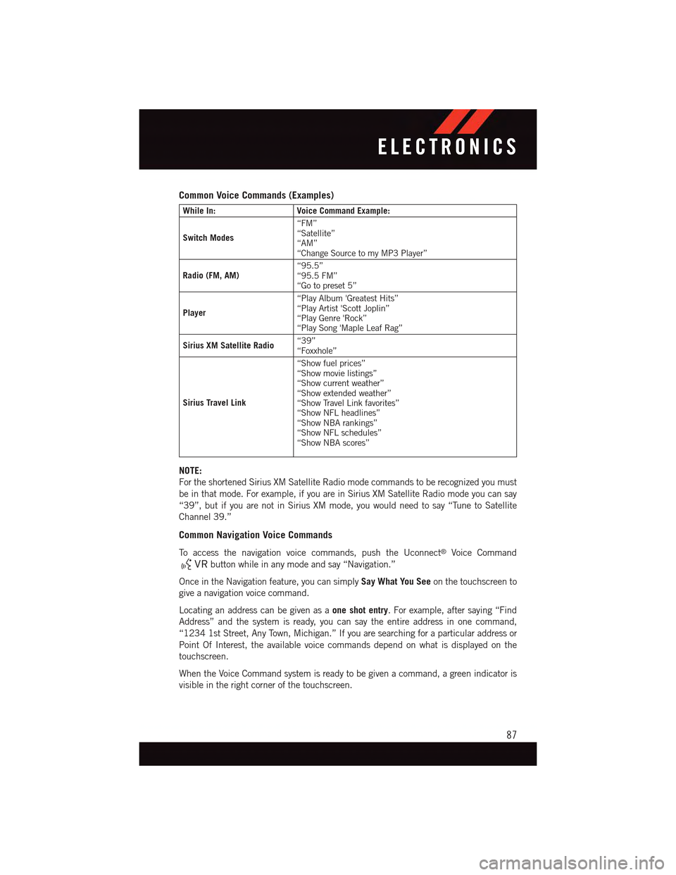
Common Voice Commands (Examples)
While In:Voice Command Example:
Switch Modes
“FM”“Satellite”“AM”“Change Source to my MP3 Player”
Radio (FM, AM)“95.5”“95.5 FM”“Go to preset 5”
Player
“Play Album 'Greatest Hits”“Play Artist 'Scott Joplin”“Play Genre 'Rock”“Play Song 'Maple Leaf Rag”
Sirius XM Satellite Radio“39”“Foxxhole”
Sirius Travel Link
“Show fuel prices”“Show movie listings”“Show current weather”“Show extended weather”“Show Travel Link favorites”“Show NFL headlines”“Show NBA rankings”“Show NFL schedules”“Show NBA scores”
NOTE:
For the shortened Sirius XM Satellite Radio mode commands to be recognized you must
be in that mode. For example, if you are in Sirius XM Satellite Radio mode you can say
“39”, but if you are not in Sirius XM mode, you would need to say “Tune to Satellite
Channel 39.”
Common Navigation Voice Commands
To a c c e s s t h e n a v i g a t i o n v o i c e c o m m a n d s , p u s h t h e U c o n n e c t®Voice Command
button while in any mode and say “Navigation.”
Once in the Navigation feature, you can simplySay What You Seeon the touchscreen to
give a navigation voice command.
Locating an address can be given as aone shot entry.Forexample,aftersaying“Find
Address” and the system is ready, you can say the entire address in one command,
“1234 1st Street, Any Town, Michigan.” If you are searching for a particular address or
Point Of Interest, the available voice commands depend on what is displayed on the
touchscreen.
When the Voice Command system is ready to be given a command, a green indicator is
visible in the right corner of the touchscreen.
ELECTRONICS
87
Page 91 of 164
•Pushthebuttoninthecentertoselectthenextpresetstation(radio)ortochangeCDs
if equipped with a CD Changer.
ELECTRONIC VEHICLE INFORMATION CENTER (EVIC) —
STANDARD (2 BUTTON)
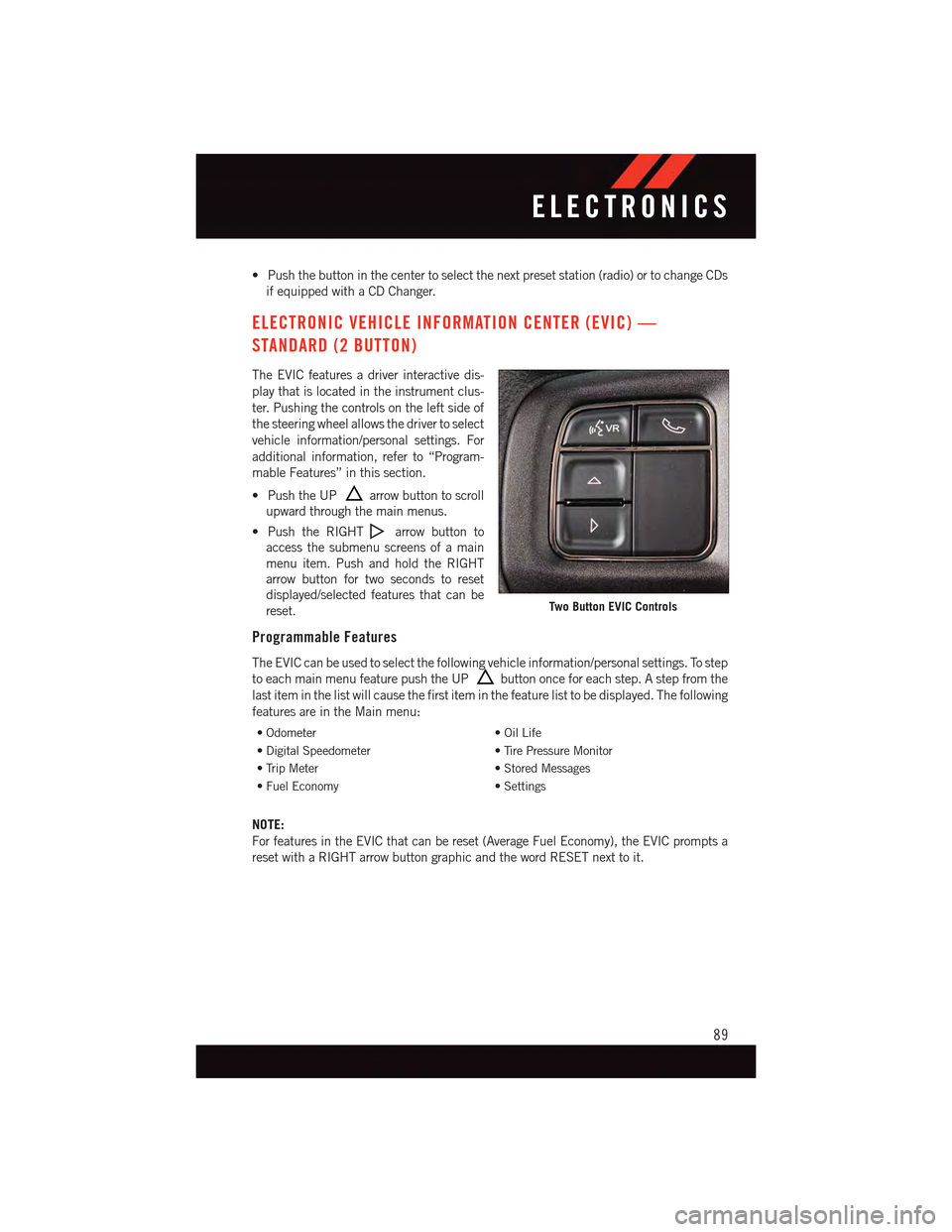
The EVIC features a driver interactive dis-
play that is located in the instrument clus-
ter. Pushing the controls on the left side of
the steering wheel allows the driver to select
vehicle information/personal settings. For
additional information, refer to “Program-
mable Features” in this section.
•PushtheUParrow button to scroll
upward through the main menus.
•PushtheRIGHTarrow button to
access the submenu screens of a main
menu item. Push and hold the RIGHT
arrow button for two seconds to reset
displayed/selected features that can be
reset.
Programmable Features
The EVIC can be used to select the following vehicle information/personal settings. To step
to each main menu feature push the UPbutton once for each step. A step from the
last item in the list will cause the first item in the feature list to be displayed. The following
features are in the Main menu:
•Odometer•OilLife
•DigitalSpeedometer•TirePressureMonitor
•TripMeter•StoredMessages
•FuelEconomy•Settings
NOTE:
For features in the EVIC that can be reset (Average Fuel Economy), the EVIC prompts a
reset with a RIGHT arrow button graphic and the word RESET next to it.
Two Button EVIC Controls
ELECTRONICS
89
Page 92 of 164
DRIVER INFORMATION DISPLAY (DID) — PREMIUM (4 BUTTON)
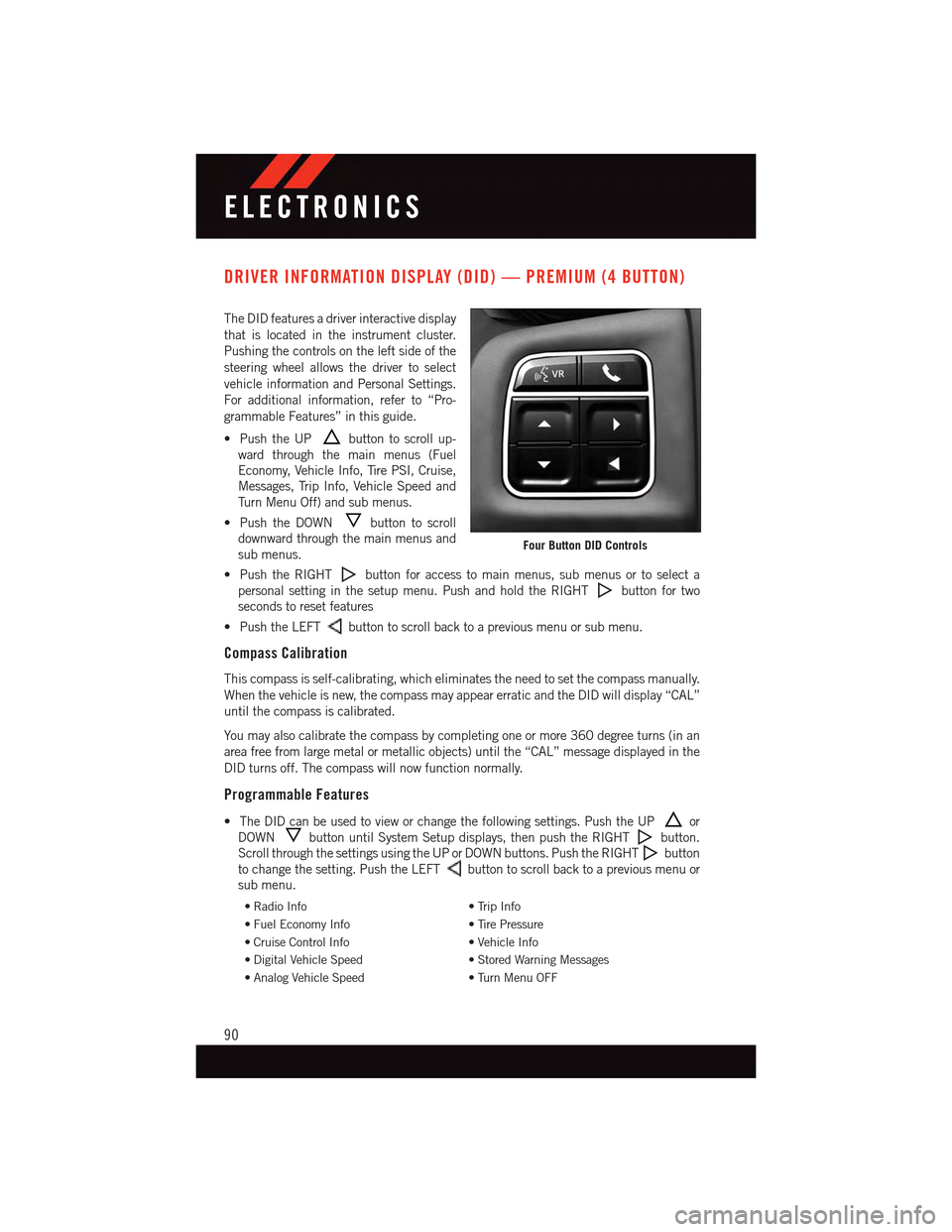
The DID features a driver interactive display
that is located in the instrument cluster.
Pushing the controls on the left side of the
steering wheel allows the driver to select
vehicle information and Personal Settings.
For additional information, refer to “Pro-
grammable Features” in this guide.
•PushtheUPbutton to scroll up-
ward through the main menus (Fuel
Economy, Vehicle Info, Tire PSI, Cruise,
Messages, Trip Info, Vehicle Speed and
Tu r n M e n u O f f ) a n d s u b m e n u s .
•PushtheDOWNbutton to scroll
downward through the main menus and
sub menus.
•PushtheRIGHTbutton for access to main menus, sub menus or to select a
personal setting in the setup menu. Push and hold the RIGHTbutton for two
seconds to reset features
•PushtheLEFTbutton to scroll back to a previous menu or sub menu.
Compass Calibration
This compass is self-calibrating, which eliminates the need to set the compass manually.
When the vehicle is new, the compass may appear erratic and the DID will display “CAL”
until the compass is calibrated.
Yo u m a y a l s o c a l i b r a t e t h e c o m p a s s b y c o m p l e t i n g o n e o r m o r e 3 6 0 d e g r e e t u r n s ( i n a n
area free from large metal or metallic objects) until the “CAL” message displayed in the
DID turns off. The compass will now function normally.
Programmable Features
•TheDIDcanbeusedtovieworchangethefollowingsettings.PushtheUPor
DOWNbutton until System Setup displays, then push the RIGHTbutton.
Scroll through the settings using the UP or DOWN buttons. Push the RIGHTbutton
to change the setting. Push the LEFTbutton to scroll back to a previous menu or
sub menu.
•RadioInfo•TripInfo
•FuelEconomyInfo•TirePressure
•CruiseControlInfo•VehicleInfo
•DigitalVehicleSpeed•StoredWarningMessages
•AnalogVehicleSpeed•TurnMenuOFF
Four Button DID Controls
ELECTRONICS
90
Page 96 of 164
Uconnect® 8.4 CUSTOMER PROGRAMMABLE FEATURES
The Uconnect®8.4 system allows you to access Customer Programmable feature settings
such as Display, Clock, Safety/Assistance, Lights, Doors & Locks, Heated Seats, Engine
Off Operation, Compass Settings, Audio, Phone/Bluetooth®and SiriusXM Setup through
buttons on the touchscreen.
Press the “More” button on the touchscreen on the bottom of the screen, then press the
“Settings” button on the touchscreen to access the Settings screen. When making a
selection, scroll up or down until the preferred setting is highlighted, then press and
release the preferred setting until a check-mark appears next to the setting, showing that
setting has been selected. The following feature settings are available:
•Display•Clock
•Safety/Assistance•Lights
•Doors&Locks•Auto-OnComfort&RemoteStart
•EngineOffOptions•CompassSettings
•Audio•Phone/Bluetooth®
•SiriusXMSetup
UNIVERSAL GARAGE DOOR OPENER (HomeLink®)
HomeLink®replaces up to three hand-held transmitters that operate devices such as
garage door openers, motorized gates, lighting or home security systems. The HomeLink®
unit is powered by your vehicles 12 Volt battery.
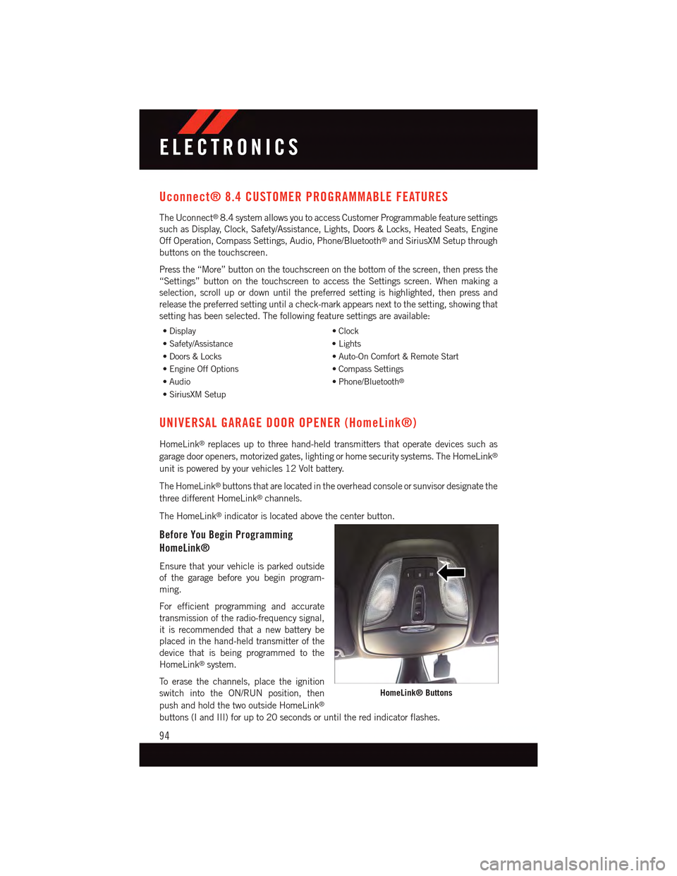
The HomeLink®buttons that are located in the overhead console or sunvisor designate the
three different HomeLink®channels.
The HomeLink®indicator is located above the center button.
Before You Begin Programming
HomeLink®
Ensure that your vehicle is parked outside
of the garage before you begin program-
ming.
For efficient programming and accurate
transmission of the radio-frequency signal,
it is recommended that a new battery be
placed in the hand-held transmitter of the
device that is being programmed to the
HomeLink®system.
To e r a s e t h e c h a n n e l s , p l a c e t h e i g n i t i o n
switch into the ON/RUN position, then
push and hold the two outside HomeLink®
buttons (I and III) for up to 20 seconds or until the red indicator flashes.
HomeLink® Buttons
ELECTRONICS
94
Page 99 of 164

POWER OUTLET
There is a 12 Volt power outlet located in
the front storage bin below the radio. This
outlet has power available when the ignition
switch in the ON position.
Asecond12Voltpoweroutletislocated
inside the center console (if equipped).
This outlet has power available when the
ignition switch is in the LOCK, ON, or ACC
position.
NOTE:
•Donotexceedthemaximumpowerof
160 Watts (13 Amps) at 12 Volts. If the
160 Watt (13 Amp) power rating is ex-
ceeded, the fuse protecting the system
will need to be replaced.
•Poweroutletsaredesignedforaccessoryplugsonly.Donotinsertanyotherobjectin
the power outlet as this will damage the outlet and blow the fuse. Improper use of the
power outlet can cause damage not covered by your new vehicle warranty.
Front Power Outlet
Power Outlet Fuses
1—F30Fuse20AmpYellowPowerOutlet — Center Console2—F84Fuse20AmpYellowCigarLighter/Power Outlet Instrument Panel
ELECTRONICS
97
Page 122 of 164

JUMP-STARTING
If your vehicle has a discharged battery it
can be jump-started using a set of jumper
cables and a battery in another vehicle or by
using a portable battery booster pack.
Jump-starting can be dangerous if done
improperly so please follow the procedures
in this section carefully.
NOTE:
When using a portable battery booster pack
follow the manufacturer’s operating instruc-
tions and precautions.
Preparations For Jump-Start
The battery in your vehicle is located in the
front of the engine compartment, behind
the left headlight assembly.
NOTE:
The positive battery post is covered with a protective cap. Lift up on the cap to gain access
to the positive battery post.
•Settheparkingbrake,shifttheautomatictransmissionintoPARK(manualtransmis-
sion in NEUTRAL) and turn the ignition to LOCK.
•Turnofftheheater,radio,andallunnecessaryelectricalaccessories.
•Ifusinganothervehicletojump-startthebattery,parkthevehiclewithinthejumper
cables reach, set the parking brake and make sure the ignition is OFF.
Jump-Starting Procedure
1. Connect the positive(+)end of the jumper cable to the positive(+)post of the vehicle
with the discharged battery.
2. Connect the opposite end of the positive(+)jumper cable to the positive(+)post of the
booster battery.
3. Connect the negative(-)end of the jumper cable to the negative(-)post of the booster
battery.
4. Connect the opposite end of the negative(-)jumper cable to a good engine ground
(exposed metal part of the discharged vehicle’s engine) away from the battery and the
fuel injection system.
5. Start the engine in the vehicle that has the booster battery, let the engine idle a few
minutes, and then start the engine in the vehicle with the discharged battery.
Positive Post (Under Cover)
WHAT TO DO IN EMERGENCIES
120
Page 141 of 164

FUSES
Interior Fuses
The interior fuses are located on the drivers side under the instrument panel.
Cavity Cartridge Fuse Mini FuseDescription
F1–20AmpYellowFrontHeatedSeats–IfEquipped
F2–20AmpYellowRear Heated Seats, Heated Steer-ing Wheel – If Equipped
F3–10AmpRedPark Assist Module, Rear Camera,Left and Right Blind Spot Sensor,Compass – If Equipped
F4–15AmpBlueInstrumentCluster
F5–10AmpRedHVAC, Humidity Sensor, In-CarTe m p e r a t u r e S e n s o r, I n s i d e M i r r o rAssembly
F18–15AmpBlueRadio
F20–10AmpRedSteering Column Control Module,Switch Bank
F21–10AmpRedDiagnosticPort
F22–10AmpRedUniversal Garage Door Opener,EOM
F23–20AmpYellowSunroof
F24–5AmpTan Run/AccessoryRelay
F25–5AmpTan TransmissionControlModule#4
F26–5AmpTan StopLampSwitch
F27–10AmpRedPneumaticLumbarSupport
MAINTAINING YOUR VEHICLE
139
Page 143 of 164
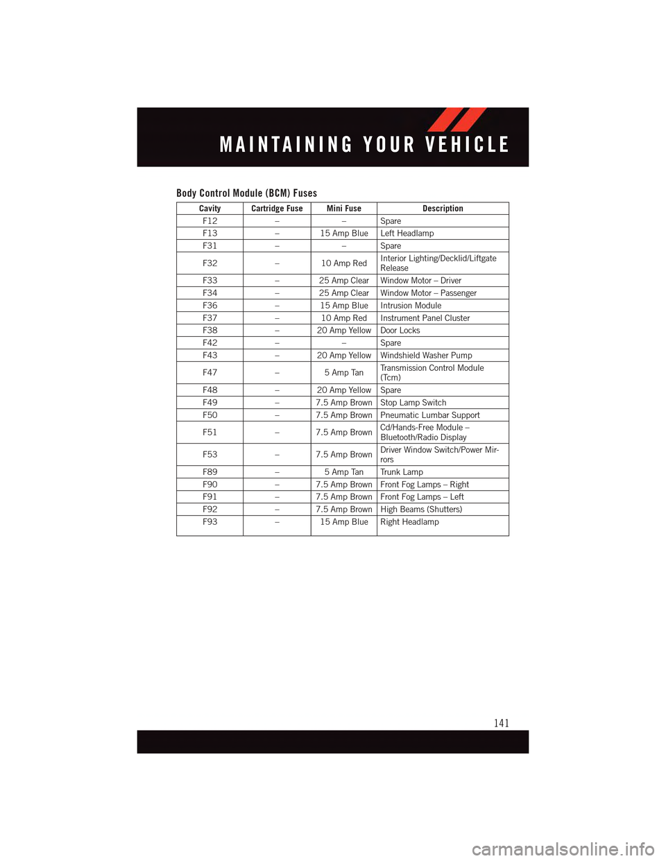
Body Control Module (BCM) Fuses
Cavity Cartridge Fuse Mini FuseDescription
F12––Spare
F13–15AmpBlueLeftHeadlamp
F31––Spare
F32–10AmpRedInterior Lighting/Decklid/LiftgateRelease
F33–25AmpClearWindowMotor–Driver
F34–25AmpClearWindowMotor–Passenger
F36–15AmpBlueIntrusionModule
F37–10AmpRedInstrumentPanelCluster
F38–20AmpYellowDoorLocks
F42––Spare
F43–20AmpYellowWindshieldWasherPump
F47–5AmpTanTr a n s m i s s i o n C o n t r o l M o d u l e(Tcm)
F48–20AmpYellowSpare
F49–7.5AmpBrownStopLampSwitch
F50–7.5AmpBrownPneumaticLumbarSupport
F51–7.5AmpBrownCd/Hands-Free Module –Bluetooth/Radio Display
F53–7.5AmpBrownDriver Window Switch/Power Mir-rors
F89–5AmpTan TrunkLamp
F90–7.5AmpBrownFrontFogLamps–Right
F91–7.5AmpBrownFrontFogLamps–Left
F92–7.5AmpBrownHighBeams(Shutters)
F93–15AmpBlueRightHeadlamp
MAINTAINING YOUR VEHICLE
141