Page 137 of 164
Required Maintenance
Refer to the Maintenance Schedules on the following pages for required maintenance.
At Every Oil Change Interval As Indicated By Oil Change Indicator System:
•Change engine oil and filter.
•Rotatethetires.Rotate at the first sign of irregular wear, even if it occurs before the oil
indicator system turns on.
•Inspect battery and clean and tighten terminals as required.
•Inspect brake pads, shoes, rotors, drums, hoses and park brake.
•Inspect engine cooling system protection and hoses.
•Inspect exhaust system.
•Inspect engine air cleaner if using in dusty or off-road conditions.
MAINTAINING YOUR VEHICLE
135
Page 138 of 164

Maintenance Chart
Mileage Or Time Passed (Whichever Comes First)
20,000
30,000
40,000
50,000
60,000
70,000
80,000
90,000
100,000
110,000
120,000
130,000
140,000
150,000
Or Years: 2 3 4 5 6 7 8 9 10 11 12 13 14 15
Or Kilometers:
32,000
48,000
64,000
80,000
96,000
112,000
128,000
144,000
160,000
176,000
192,000
208,000
224,000
240,000
Additional InspectionsInspect CV joint boots. X X X X XInspect front suspension, tie rod ends and replace as necessary. X X X X X X XInspect brake linings, parking brake function. X X X X X X XAdditional MaintenanceReplace the cabin/air conditioning filter. X X X X X X XReplace the engine air cleaner filter. X X X X XReplace the spark plugs (1.4L Turbo Engine).** X X X X XReplace the spark plugs (2.0L and 2.4L Engine).**
X
Flush and replace the engine coolant at 10 years or 150,000 miles(240,000 km) whichever comes first.
XX
Change the transmission fluid (manual, or 1.4L turbo automatic) if using yourvehicle for any of the following: trailer towing, heavy loading, taxi, police, deliv-ery service (commercial service), off-road, desert operation or more than 50% ofyour driving is at sustained speeds during hot weather, above 90°F (32°C).
XX X
Change the automatic transmission fluid and filter (2.0L, 2.4L engines only)if you frequently drive: on rough or unpaved roads, on mountain roads, onshort trips, in heavy city traffic during hot weather, or while towing a trailer, orif you use the vehicle for police, taxi, or in a commercial fleet.
XX
Inspect and replace PCV valve if necessary.
X
Replace the timing belt (1.4L Turbo Engine).
X
** The spark plug change interval is mileage based only, yearly intervals do not apply.
MAINTAINING YOUR VEHICLE
136
Page 139 of 164
WARNING!
•Youcanbebadlyinjuredworkingonoraroundamotorvehicle.Doonlyserviceworkforwhichyouhavetheknowledgeandtheright
equipment. If you have any doubt about your ability to perform a service job, take your vehicle to a competent mechanic.
•Failuretoproperlyinspectandmaintainyourvehiclecouldresultinacomponentmalfunctionandeffectvehiclehandlingand
performance. This could cause an accident.
MAINTAINING YOUR VEHICLE
137
Page 140 of 164
MAINTENANCE RECORD
Odometer Date Signature, Autho-
rized Service Center
20,000 Miles(32,000 km) or2Years30,000 Miles(48,000 km) or3Years40,000 Miles(64,000 km) or4Years50,000 Miles(80,000 km) or5Years60,000 Miles(96,000 km) or6Years70,000 Miles(112,000 km) or7Years80,000 Miles(128,000 km) or8Years
Odometer Date Signature, Autho-
rized Service Center
90,000 Miles(144,000 km) or9Years100,000 Miles(160,000 km) or10 Years110,000 Miles(176,000 km) or11 Years120,000 Miles(192,000 km) or12 Years130,000 Miles(208,000 km) or13 Years140,000 Miles(224,000 km) or14 Years150,000 Miles(240,000 km) or15 Years
MAINTAINING YOUR VEHICLE
138
Page 141 of 164
FUSES
Interior Fuses
The interior fuses are located on the drivers side under the instrument panel.
Cavity Cartridge Fuse Mini FuseDescription
F1–20AmpYellowFrontHeatedSeats–IfEquipped
F2–20AmpYellowRear Heated Seats, Heated Steer-ing Wheel – If Equipped
F3–10AmpRedPark Assist Module, Rear Camera,Left and Right Blind Spot Sensor,Compass – If Equipped
F4–15AmpBlueInstrumentCluster
F5–10AmpRedHVAC, Humidity Sensor, In-CarTe m p e r a t u r e S e n s o r, I n s i d e M i r r o rAssembly
F18–15AmpBlueRadio
F20–10AmpRedSteering Column Control Module,Switch Bank
F21–10AmpRedDiagnosticPort
F22–10AmpRedUniversal Garage Door Opener,EOM
F23–20AmpYellowSunroof
F24–5AmpTan Run/AccessoryRelay
F25–5AmpTan TransmissionControlModule#4
F26–5AmpTan StopLampSwitch
F27–10AmpRedPneumaticLumbarSupport
MAINTAINING YOUR VEHICLE
139
Page 142 of 164

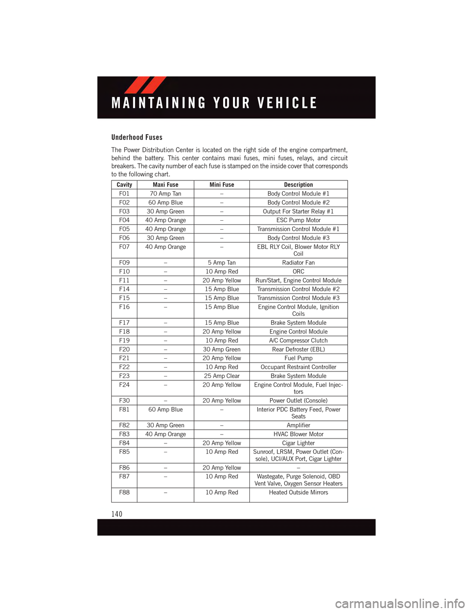
Underhood Fuses
The Power Distribution Center is located on the right side of the engine compartment,
behind the battery. This center contains maxi fuses, mini fuses, relays, and circuit
breakers. The cavity number of each fuse is stamped on the inside cover that corresponds
to the following chart.
Cavity Maxi FuseMini FuseDescription
F01 70 Amp Tan–Body Control Module #1
F02 60 Amp Blue–Body Control Module #2
F03 30 Amp Green–Output For Starter Relay #1
F04 40 Amp Orange–ESC Pump Motor
F05 40 Amp Orange–Tr a n s m i s s i o n C o n t r o l M o d u l e # 1
F06 30 Amp Green–Body Control Module #3
F07 40 Amp Orange–EBL RLY Coil, Blower Motor RLYCoil
F09–5AmpTanRadiator Fan
F10–10 Amp RedORC
F11–20 Amp Yellow Run/Start, Engine Control Module
F14–15 Amp Blue Transmission Control Module #2
F15–15 Amp Blue Transmission Control Module #3
F16–15 Amp Blue Engine Control Module, IgnitionCoils
F17–15 Amp BlueBrake System Module
F18–20 Amp Yellow Engine Control Module
F19–10 Amp RedA/C Compressor Clutch
F20–30 Amp GreenRear Defroster (EBL)
F21–20 Amp YellowFuel Pump
F22–10 Amp Red Occupant Restraint Controller
F23–25 Amp ClearBrake System Module
F24–20 Amp Yellow Engine Control Module, Fuel Injec-tors
F30–20 Amp Yellow Power Outlet (Console)
F81 60 Amp Blue–Interior PDC Battery Feed, PowerSeats
F82 30 Amp Green–Amplifier
F83 40 Amp Orange–HVAC Blower Motor
F84–20 Amp YellowCigar Lighter
F85–10 Amp Red Sunroof, LRSM, Power Outlet (Con-sole), UCI/AUX Port, Cigar Lighter
F86–20 Amp Yellow–
F87–10 Amp Red Wastegate, Purge Solenoid, OBDVent Valve, Oxygen Sensor Heaters
F88–10 Amp Red Heated Outside Mirrors
MAINTAINING YOUR VEHICLE
140
Page 143 of 164
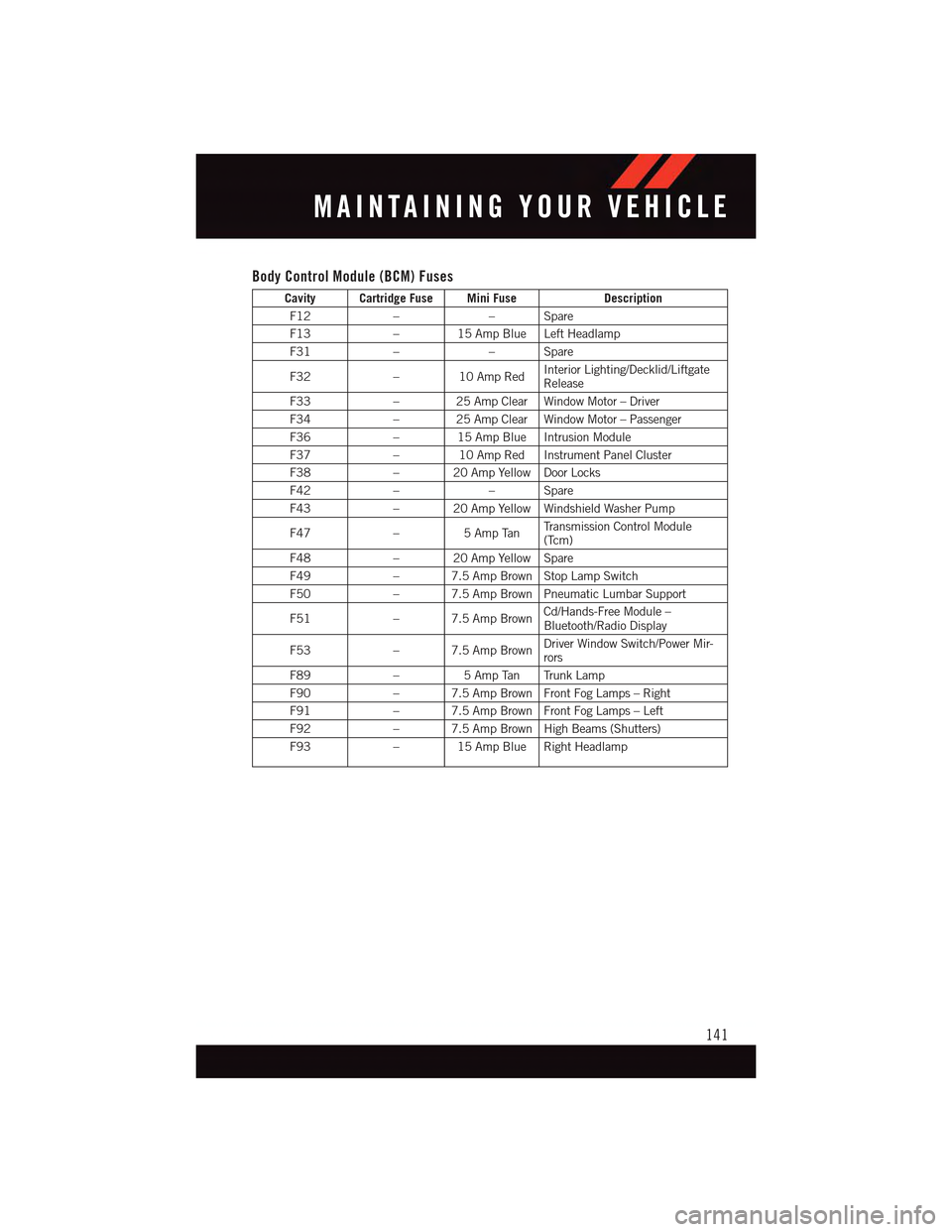
Body Control Module (BCM) Fuses
Cavity Cartridge Fuse Mini FuseDescription
F12––Spare
F13–15AmpBlueLeftHeadlamp
F31––Spare
F32–10AmpRedInterior Lighting/Decklid/LiftgateRelease
F33–25AmpClearWindowMotor–Driver
F34–25AmpClearWindowMotor–Passenger
F36–15AmpBlueIntrusionModule
F37–10AmpRedInstrumentPanelCluster
F38–20AmpYellowDoorLocks
F42––Spare
F43–20AmpYellowWindshieldWasherPump
F47–5AmpTanTr a n s m i s s i o n C o n t r o l M o d u l e(Tcm)
F48–20AmpYellowSpare
F49–7.5AmpBrownStopLampSwitch
F50–7.5AmpBrownPneumaticLumbarSupport
F51–7.5AmpBrownCd/Hands-Free Module –Bluetooth/Radio Display
F53–7.5AmpBrownDriver Window Switch/Power Mir-rors
F89–5AmpTan TrunkLamp
F90–7.5AmpBrownFrontFogLamps–Right
F91–7.5AmpBrownFrontFogLamps–Left
F92–7.5AmpBrownHighBeams(Shutters)
F93–15AmpBlueRightHeadlamp
MAINTAINING YOUR VEHICLE
141
Page 144 of 164

TIRE PRESSURES
Check the inflation pressure of each tire, including the spare tire, at least monthly and
inflate to the recommended pressure for your vehicle.
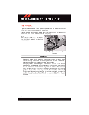
The tire pressures recommended for your vehicle are found on the “Tire and Loading
Information” label located on the driver’s side door opening.
NOTE:
Refer to the Owner's Manual on the DVD for
more information regarding tire warnings
and instructions.
WARNING!
•Overloadingofyourtiresisdangerous.Overloadingcancausetirefailure,affect
vehicle handling, and increase your stopping distance. Use tires of the recom-
mended load capacity for your vehicle. Never overload them.
•Improperlyinflatedtiresaredangerousandcancausecollisions.Under-inflation
increases tire flexing and can result in over-heating and tire failure. Over-inflation
reduces a tire’s ability to cushion shock. Objects on the road and chuck holes can
cause damage that results in tire failure. Unequal tire pressures can cause steering
problems. You could lose control of your vehicle. Over-inflated or under-inflated
tires can affect vehicle handling and can fail suddenly, resulting in loss of vehicle
control. Always drive with each tire inflated to the recommended cold tire inflation
pressure.
Tire And Loading Information Location(Example)
MAINTAINING YOUR VEHICLE
142