2015 BMW X1 SDRIVE28I light
[x] Cancel search: lightPage 253 of 297

Headlight setting
Changing the bulbs and lights may influence
the headlight settings. Have the headlight set‐
ting checked by a service center and corrected
if necessary after changing bulbs or lights.
Removing the headlight cover
The high-beam bulbs can be replaced via the
engine compartment, and the low beam and
turn signal bulbs can be replaced via a folding
cover in the wheel arch.1High-beam cover2Low beam cover3Turn signal bulb socket
To remove the covers:
▷High-beams: fold out the bracket, arrow 4,
and take the cover out of the guide.▷Low beams: unscrew the cover, arrow 5.
Attach the covers carefully
When attaching the covers, proceed
carefully; otherwise, leaks may occur, causing
damage to the headlamp system.◀
Proceed in reverse order when attaching the
covers.
Access via the wheel arch For low beams and turn signals only:
1.Turn the wheel inward.2.Open the folding cover in the wheel arch.
To open the locks, turn them counter‐clockwise all the way using a coin, for ex‐
ample.
Halogen headlights
At a glance
1High-beams/headlight flasher2Parking lights3Low beams4Turn signal
Low beams and high-beams Wear protective goggles and gloves
Halogen bulbs are pressurized. There‐
fore, wear protective goggles and gloves. Oth‐
erwise, there is a danger of injuries if the bulb
is accidentally damaged during replacement.◀
The low beams and high-beams have separate
covers.
Seite 251Replacing componentsMobility251
Online Edition for Part no. 01 40 2 954 052 - II/15
Page 254 of 297
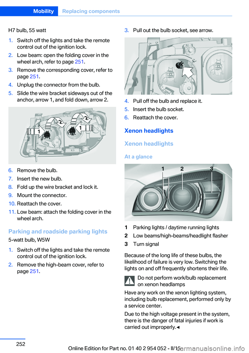
H7 bulb, 55 watt1.Switch off the lights and take the remote
control out of the ignition lock.2.Low beam: open the folding cover in the
wheel arch, refer to page 251.3.Remove the corresponding cover, refer to
page 251.4.Unplug the connector from the bulb.5.Slide the wire bracket sideways out of the
anchor, arrow 1, and fold down, arrow 2.6.Remove the bulb.7.Insert the new bulb.8.Fold up the wire bracket and lock it.9.Mount the connector.10.Reattach the cover.11.Low beam: attach the folding cover in the
wheel arch.
Parking and roadside parking lights
5-watt bulb, W5W
1.Switch off the lights and take the remote
control out of the ignition lock.2.Remove the high-beam cover, refer to
page 251.3.Pull out the bulb socket, see arrow.4.Pull off the bulb and replace it.5.Insert the bulb socket.6.Reattach the cover.
Xenon headlights
Xenon headlights
At a glance
1Parking lights / daytime running lights2Low beams/high-beams/headlight flasher3Turn signal
Because of the long life of these bulbs, the
likelihood of failure is very low. Switching the
lights on and off frequently shortens their life.
Do not perform work/bulb replacement
on xenon headlamps
Have any work on the xenon lighting system,
including bulb replacement, performed only by
a service center.
Due to the high voltage present in the system,
there is the danger of fatal injuries if work is
carried out improperly.◀
Seite 252MobilityReplacing components252
Online Edition for Part no. 01 40 2 954 052 - II/15
Page 255 of 297
Adhere to the general instructions, refer to
page 250.
With Xenon headlights, the following lights are
designed with LED technology:▷Parking and roadside parking lights.▷Daytime running lights.
Contact your service center in the event of a
malfunction.
Parking lights and roadside parking
lights, daytime running lights
H8 bulb, 35 watt
1.Switch off the lights and take the remote
control out of the ignition lock.2.Remove the high-beam cover, refer to
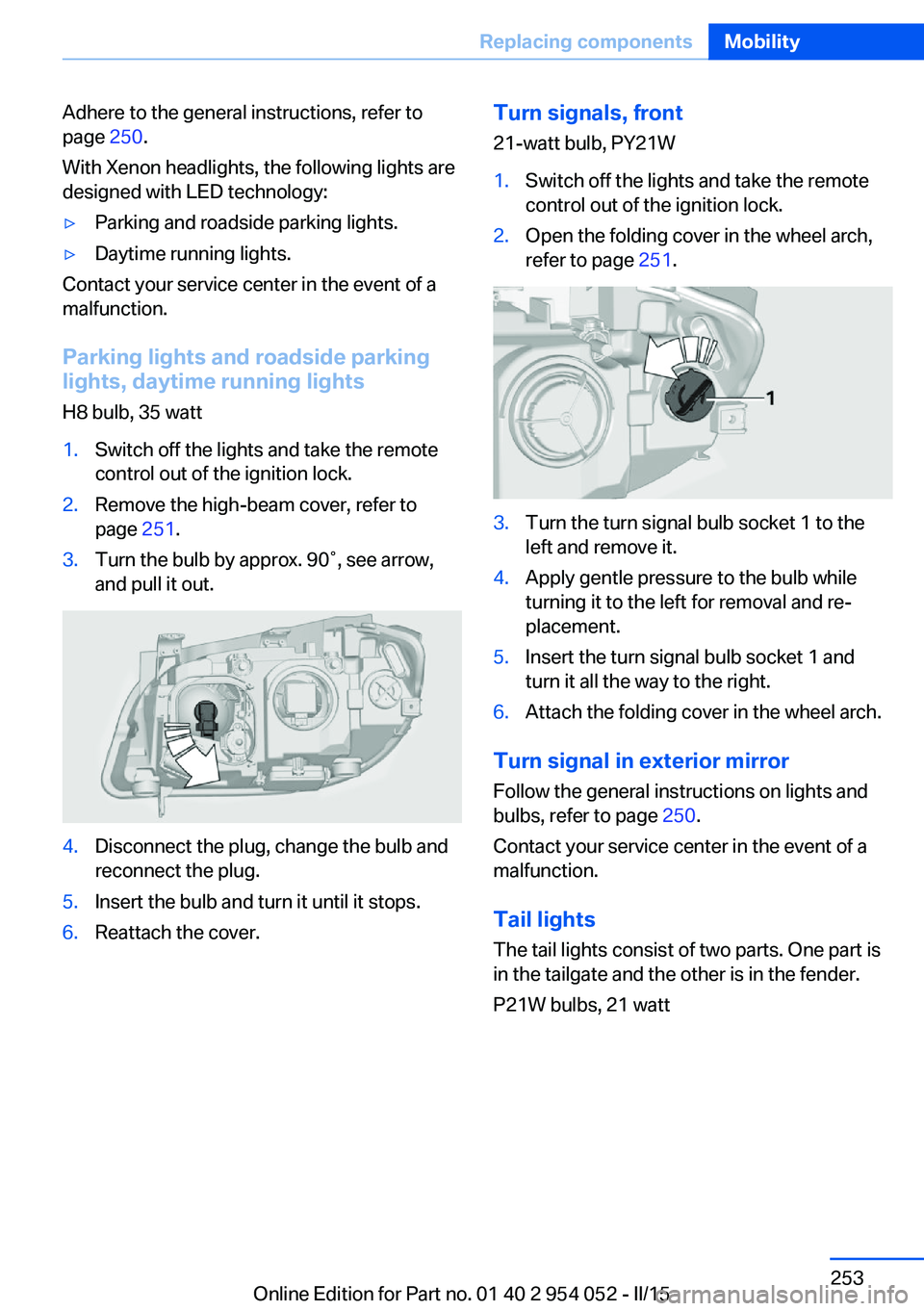
page 251.3.Turn the bulb by approx. 90˚, see arrow,
and pull it out.4.Disconnect the plug, change the bulb and
reconnect the plug.5.Insert the bulb and turn it until it stops.6.Reattach the cover.Turn signals, front
21-watt bulb, PY21W1.Switch off the lights and take the remote
control out of the ignition lock.2.Open the folding cover in the wheel arch,
refer to page 251.3.Turn the turn signal bulb socket 1 to the
left and remove it.4.Apply gentle pressure to the bulb while
turning it to the left for removal and re‐
placement.5.Insert the turn signal bulb socket 1 and
turn it all the way to the right.6.Attach the folding cover in the wheel arch.
Turn signal in exterior mirror
Follow the general instructions on lights and
bulbs, refer to page 250.
Contact your service center in the event of a
malfunction.
Tail lights
The tail lights consist of two parts. One part is
in the tailgate and the other is in the fender.
P21W bulbs, 21 watt
Seite 253Replacing componentsMobility253
Online Edition for Part no. 01 40 2 954 052 - II/15
Page 256 of 297
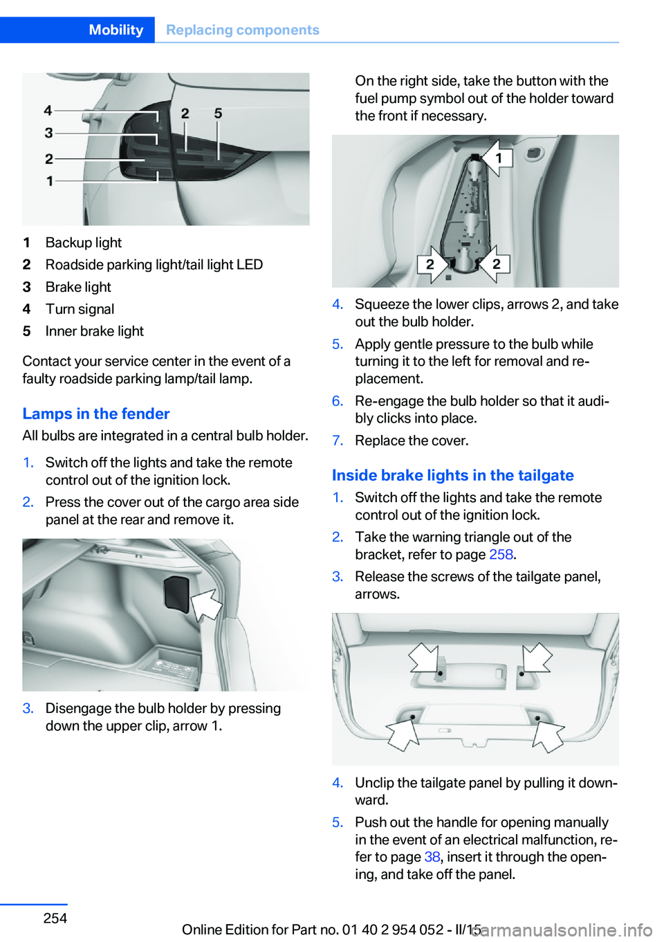
1Backup light2Roadside parking light/tail light LED3Brake light4Turn signal5Inner brake light
Contact your service center in the event of a
faulty roadside parking lamp/tail lamp.
Lamps in the fender All bulbs are integrated in a central bulb holder.
1.Switch off the lights and take the remote
control out of the ignition lock.2.Press the cover out of the cargo area side
panel at the rear and remove it.3.Disengage the bulb holder by pressing
down the upper clip, arrow 1.On the right side, take the button with the
fuel pump symbol out of the holder toward
the front if necessary.4.Squeeze the lower clips, arrows 2, and take
out the bulb holder.5.Apply gentle pressure to the bulb while
turning it to the left for removal and re‐
placement.6.Re-engage the bulb holder so that it audi‐
bly clicks into place.7.Replace the cover.
Inside brake lights in the tailgate
1.Switch off the lights and take the remote
control out of the ignition lock.2.Take the warning triangle out of the
bracket, refer to page 258.3.Release the screws of the tailgate panel,
arrows.4.Unclip the tailgate panel by pulling it down‐
ward.5.Push out the handle for opening manually
in the event of an electrical malfunction, re‐
fer to page 38, insert it through the open‐
ing, and take off the panel.Seite 254MobilityReplacing components254
Online Edition for Part no. 01 40 2 954 052 - II/15
Page 258 of 297
General information
Ensure that the battery is sufficiently charged
to achieve the full battery life.
It may be necessary to charge the battery in
the following cases:▷When the vehicle is frequently used to
drive short distances.▷When the vehicle has not been driven for
more than one month.
Starting aid terminals
Only charge using the starting aid terminals,
refer to page 259, in the engine compartment
while the engine is switched off.
Power failure
After a temporary power loss, some equipment
needs to be reinitialized.
Individual settings need to be reprogrammed:
▷Seat and mirror memory: store the posi‐
tions again, refer to page 50.▷Time: update, refer to page 77.▷Date: update, refer to page 78.▷Radio station: save again, refer to
page 168.▷Navigation system: wait for the navigation
system to be operational.▷Panoramic glass sunroof: it may only be
possible to tilt the roof. Have the system
initialized by the service center.▷Digital compass: recalibrate, refer to
page 117.▷xDrive: the system automatically initializes
as you drive. During this time, indicator
lamps light up. If the lamps do not disap‐
pear during the current trip, have the sys‐
tem checked.
Disposing of old batteries
Have old batteries disposed of by your
service center or bring them to a recy‐
cling center.
Maintain the battery in an upright position for
transport and storage. Secure the battery so
that it does not tip over during transport.
Fuses Replacing fuses
Never attempt to repair a blown fuse and
do not replace a defective fuse with a substi‐
tute of another color or amperage rating; this
could lead to a circuit overload, ultimately re‐
sulting in a fire in the vehicle.◀
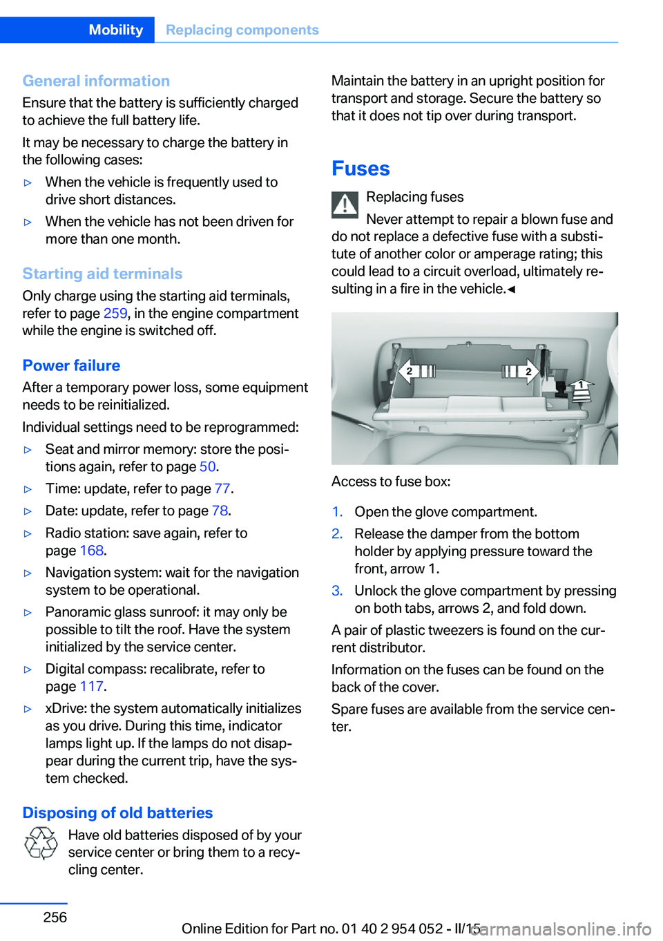
Access to fuse box:
1.Open the glove compartment.2.Release the damper from the bottom
holder by applying pressure toward the
front, arrow 1.3.Unlock the glove compartment by pressing
on both tabs, arrows 2, and fold down.
A pair of plastic tweezers is found on the cur‐
rent distributor.
Information on the fuses can be found on the
back of the cover.
Spare fuses are available from the service cen‐
ter.
Seite 256MobilityReplacing components256
Online Edition for Part no. 01 40 2 954 052 - II/15
Page 259 of 297
Breakdown assistanceVehicle equipment
This chapter describes all series equipment as
well as country-specific and special equipment
offered for this model series. Therefore, it also
describes equipment that may not be found in
your vehicle, for instance due to the selected
special equipment or the country version. This
also applies to safety-related functions and
systems.
When using the features and systems descri‐
bed here, adhere to local regulations.
Hazard warning flashers
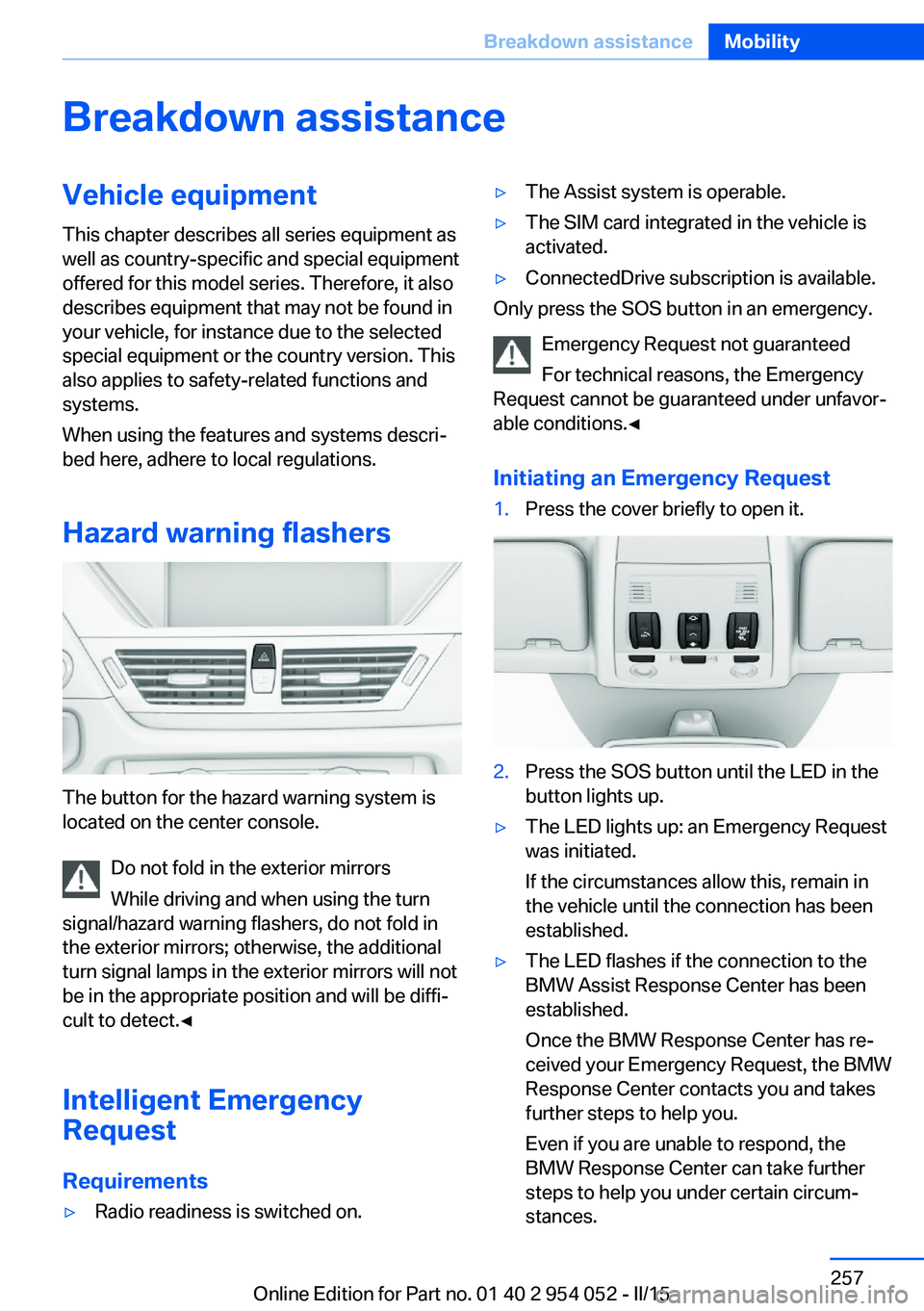
The button for the hazard warning system is
located on the center console.
Do not fold in the exterior mirrors
While driving and when using the turn
signal/hazard warning flashers, do not fold in
the exterior mirrors; otherwise, the additional
turn signal lamps in the exterior mirrors will not
be in the appropriate position and will be diffi‐
cult to detect.◀
Intelligent Emergency
Request
Requirements
▷Radio readiness is switched on.▷The Assist system is operable.▷The SIM card integrated in the vehicle is
activated.▷ConnectedDrive subscription is available.
Only press the SOS button in an emergency.
Emergency Request not guaranteed
For technical reasons, the Emergency
Request cannot be guaranteed under unfavor‐
able conditions.◀
Initiating an Emergency Request
1.Press the cover briefly to open it.2.Press the SOS button until the LED in the
button lights up.▷The LED lights up: an Emergency Request
was initiated.
If the circumstances allow this, remain in
the vehicle until the connection has been
established.▷The LED flashes if the connection to the
BMW Assist Response Center has been
established.
Once the BMW Response Center has re‐
ceived your Emergency Request, the BMW
Response Center contacts you and takes
further steps to help you.
Even if you are unable to respond, the
BMW Response Center can take further
steps to help you under certain circum‐
stances.Seite 257Breakdown assistanceMobility257
Online Edition for Part no. 01 40 2 954 052 - II/15
Page 262 of 297
Automatic transmission, 8-gear:
transporting your vehicle
Note Your vehicle is not permitted to be towed.
Therefore, contact a service center in the
event of a breakdown.
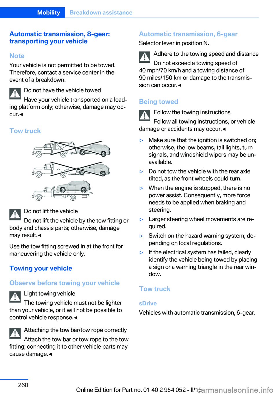
Do not have the vehicle towed
Have your vehicle transported on a load‐
ing platform only; otherwise, damage may oc‐
cur.◀
Tow truck
Do not lift the vehicle
Do not lift the vehicle by the tow fitting or
body and chassis parts; otherwise, damage
may result.◀
Use the tow fitting screwed in at the front for
maneuvering the vehicle only.
Towing your vehicle
Observe before towing your vehicle Light towing vehicle
The towing vehicle must not be lighter
than your vehicle, or it will not be possible to
control vehicle response.◀
Attaching the tow bar/tow rope correctly
Attach the tow bar or tow rope to the tow
fitting; connecting it to other vehicle parts may
cause damage.◀
Automatic transmission, 6-gear
Selector lever in position N.
Adhere to the towing speed and distance
Do not exceed a towing speed of
40 mph/70 km/h and a towing distance of
90 miles/150 km or damage to the transmis‐
sion can occur.◀
Being towed Follow the towing instructions
Follow all towing instructions, or vehicle
damage or accidents may occur.◀▷Make sure that the ignition is switched on;
otherwise, the low beams, tail lights, turn
signals, and windshield wipers may be un‐
available.▷Do not tow the vehicle with the rear axle
tilted, as the front wheels could turn.▷When the engine is stopped, there is no
power assist. Consequently, more force
needs to be applied when braking and
steering.▷Larger steering wheel movements are re‐
quired.▷Switch on the hazard warning system, de‐
pending on local regulations.▷If the electrical system has failed, clearly
identify the vehicle being towed by placing
a sign or a warning triangle in the rear win‐
dow.
Tow truck
sDrive
Vehicles with automatic transmission, 6-gear.
Seite 260MobilityBreakdown assistance260
Online Edition for Part no. 01 40 2 954 052 - II/15
Page 263 of 297
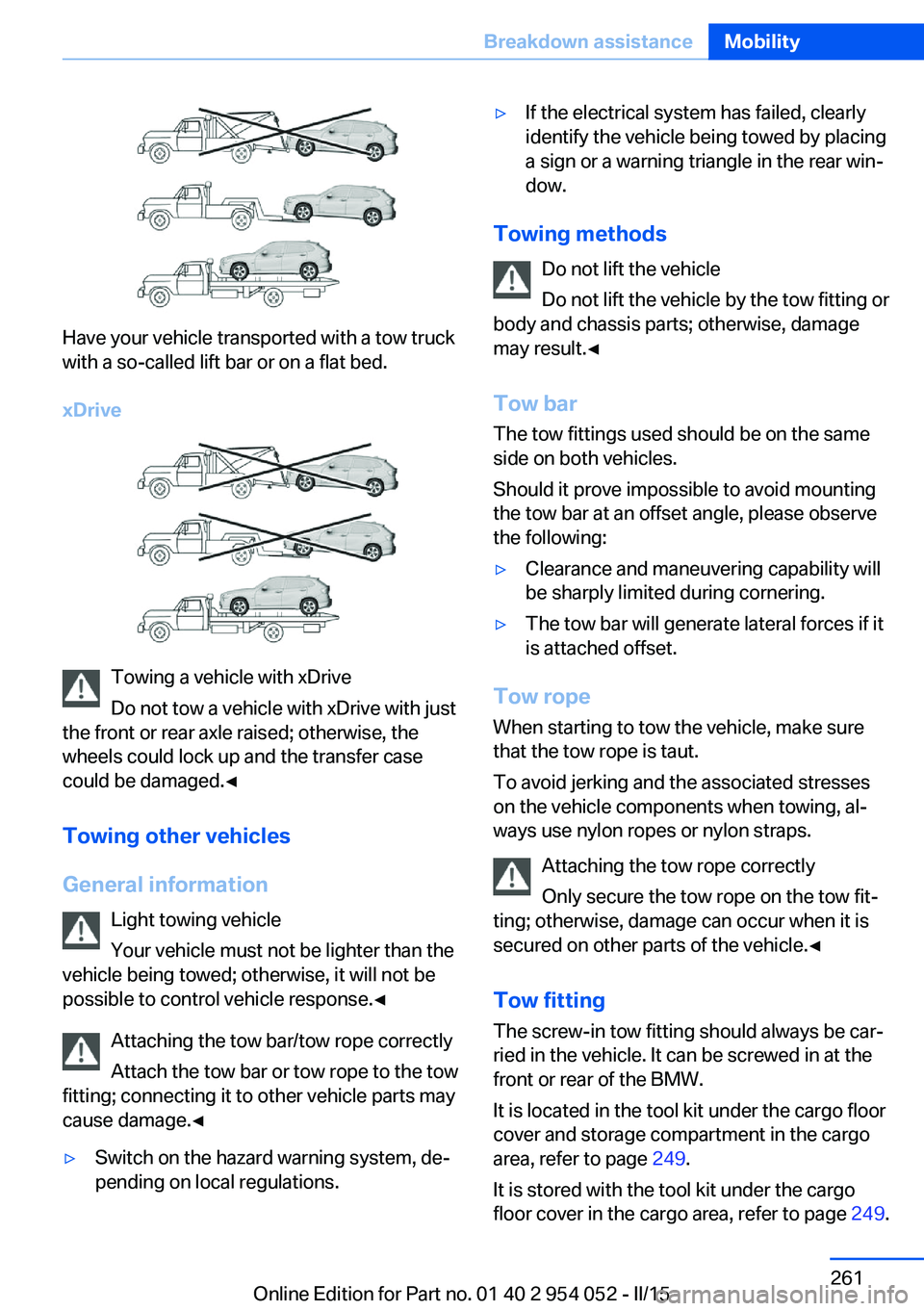
Have your vehicle transported with a tow truck
with a so-called lift bar or on a flat bed.
xDrive
Towing a vehicle with xDrive
Do not tow a vehicle with xDrive with just
the front or rear axle raised; otherwise, the
wheels could lock up and the transfer case
could be damaged.◀
Towing other vehicles
General information Light towing vehicle
Your vehicle must not be lighter than the
vehicle being towed; otherwise, it will not be possible to control vehicle response.◀
Attaching the tow bar/tow rope correctly
Attach the tow bar or tow rope to the tow
fitting; connecting it to other vehicle parts may
cause damage.◀
▷Switch on the hazard warning system, de‐
pending on local regulations.▷If the electrical system has failed, clearly
identify the vehicle being towed by placing
a sign or a warning triangle in the rear win‐
dow.
Towing methods
Do not lift the vehicle
Do not lift the vehicle by the tow fitting or
body and chassis parts; otherwise, damage
may result.◀
Tow bar The tow fittings used should be on the same
side on both vehicles.
Should it prove impossible to avoid mounting
the tow bar at an offset angle, please observe
the following:
▷Clearance and maneuvering capability will
be sharply limited during cornering.▷The tow bar will generate lateral forces if it
is attached offset.
Tow rope
When starting to tow the vehicle, make sure
that the tow rope is taut.
To avoid jerking and the associated stresses
on the vehicle components when towing, al‐
ways use nylon ropes or nylon straps.
Attaching the tow rope correctly
Only secure the tow rope on the tow fit‐
ting; otherwise, damage can occur when it is
secured on other parts of the vehicle.◀
Tow fitting
The screw-in tow fitting should always be car‐
ried in the vehicle. It can be screwed in at the
front or rear of the BMW.
It is located in the tool kit under the cargo floor
cover and storage compartment in the cargo
area, refer to page 249.
It is stored with the tool kit under the cargo floor cover in the cargo area, refer to page 249.
Seite 261Breakdown assistanceMobility261
Online Edition for Part no. 01 40 2 954 052 - II/15