2015 BMW I8 tow
[x] Cancel search: towPage 59 of 224
Malfunction
Remote control detection by the vehicle can
among others be malfunctioning under the fol‐
lowing circumstances:▷The battery of the remote control is dis‐
charged. Replace the battery, refer to
page 39.▷Interference of the radio connection from
transmission towers or other equipment
with high transmit power.▷Shielding of the remote control due to
metal objects.▷Interference of the radio connection from
mobile phones or other electronic devices
in direct proximity.
Do not transport the remote control together
with metal objects or electronic devices.
In the case of interference, the vehicle can also
be unlocked and locked from the outside with‐
out remote control, refer to page 43.
For US owners only
The transmitter and receiver units comply with
part 15 of the FCC/Federal Communication
Commission regulations. Operation is gov‐
erned by the following:
FCC ID:
▷LX8766S.▷LX8766E.▷LX8CAS.▷LX8CAS2.▷MYTCAS4.
Compliance statement:
This device complies with part 15 of the FCC
Rules. Operation is subject to the following
two conditions:
▷This device may not cause harmful inter‐
ference, and▷this device must accept any interference
received, including interference that may
cause undesired operation.Any unauthorized modifications or changes to
these devices could void the user's authority to
operate this equipment.
Without remote control
Locking from the outside1.Close the driver's door from the outside.2.Enter the vehicle via the front passenger
side and close front passenger door.3. Press button for central locking
system.
Vehicle is locked.4.Unlock the front passenger door via the
lever in the door frame, refer to page 44.5.Exit the vehicle on the front passenger
side:
Make sure that the remote control is not in
the vehicle.6.Close the front passenger door.
Unlocking from the outside
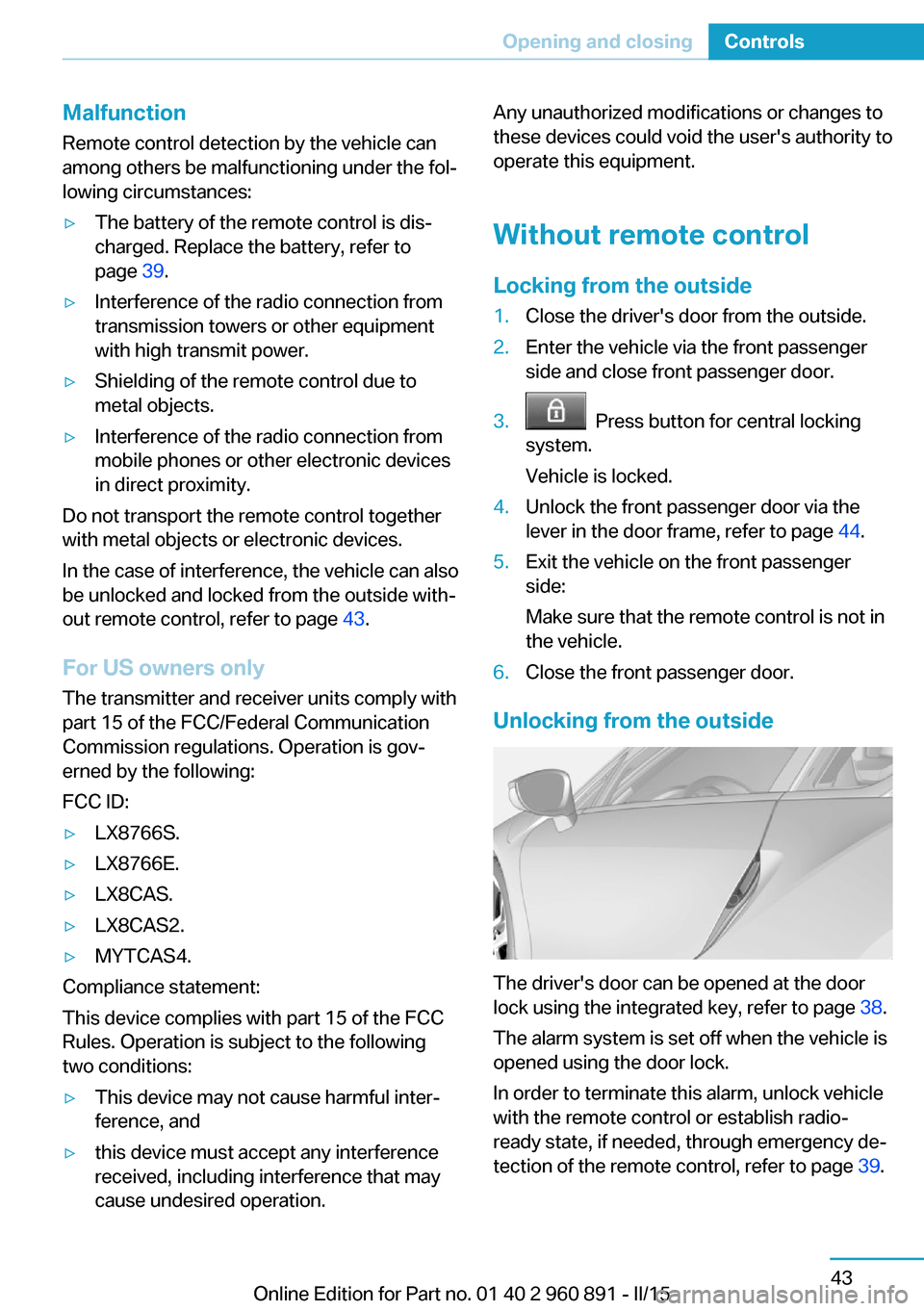
The driver's door can be opened at the door
lock using the integrated key, refer to page 38.
The alarm system is set off when the vehicle is
opened using the door lock.
In order to terminate this alarm, unlock vehicle
with the remote control or establish radio-
ready state, if needed, through emergency de‐
tection of the remote control, refer to page 39.
Seite 43Opening and closingControls43
Online Edition for Part no. 01 40 2 960 891 - II/15
Page 62 of 224
Locking
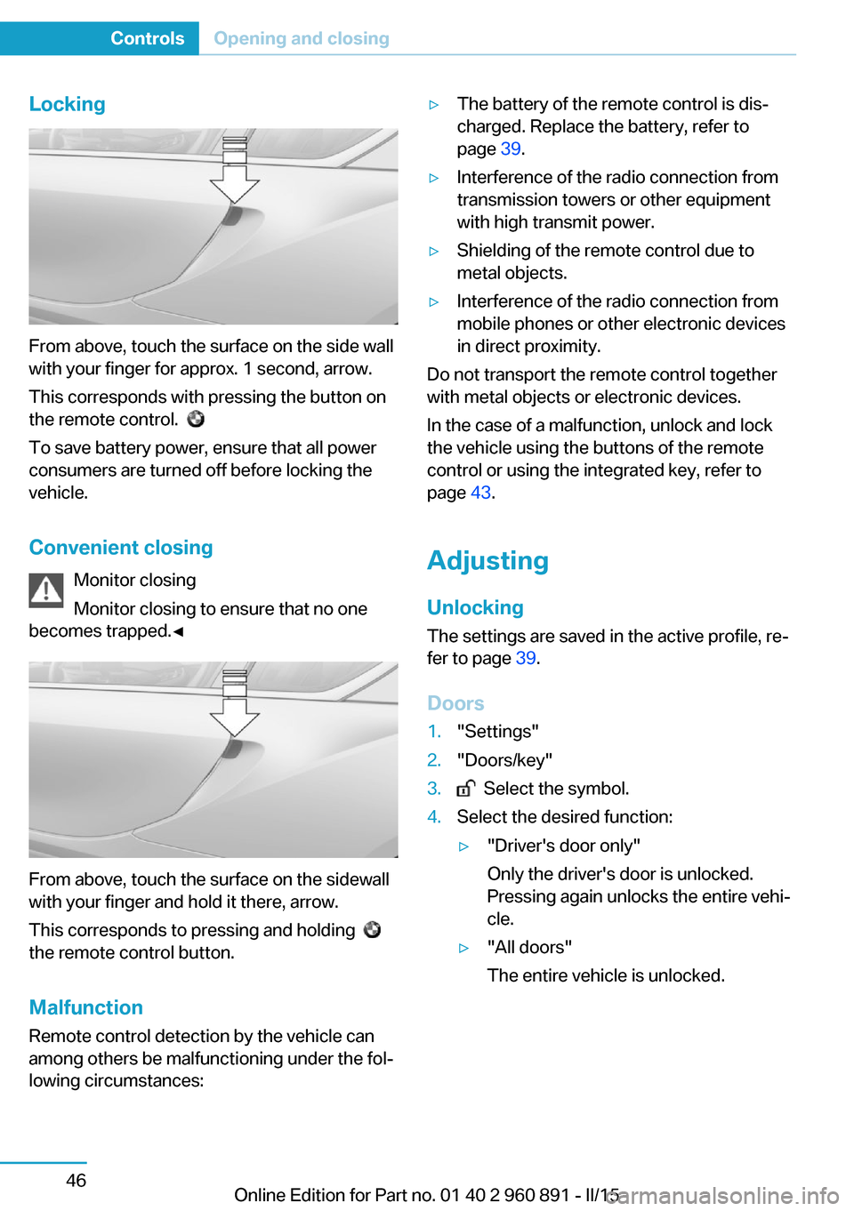
From above, touch the surface on the side wall
with your finger for approx. 1 second, arrow.
This corresponds with pressing the button on
the remote control.
To save battery power, ensure that all power
consumers are turned off before locking the
vehicle.
Convenient closing Monitor closing
Monitor closing to ensure that no one
becomes trapped.◀
From above, touch the surface on the sidewall
with your finger and hold it there, arrow.
This corresponds to pressing and holding
the remote control button.
Malfunction
Remote control detection by the vehicle can
among others be malfunctioning under the fol‐
lowing circumstances:
▷The battery of the remote control is dis‐
charged. Replace the battery, refer to
page 39.▷Interference of the radio connection from
transmission towers or other equipment
with high transmit power.▷Shielding of the remote control due to
metal objects.▷Interference of the radio connection from
mobile phones or other electronic devices
in direct proximity.
Do not transport the remote control together
with metal objects or electronic devices.
In the case of a malfunction, unlock and lock
the vehicle using the buttons of the remote
control or using the integrated key, refer to
page 43.
Adjusting
Unlocking The settings are saved in the active profile, re‐
fer to page 39.
Doors
1."Settings"2."Doors/key"3. Select the symbol.4.Select the desired function:▷"Driver's door only"
Only the driver's door is unlocked.
Pressing again unlocks the entire vehi‐
cle.▷"All doors"
The entire vehicle is unlocked.Seite 46ControlsOpening and closing46
Online Edition for Part no. 01 40 2 960 891 - II/15
Page 85 of 224

▷To switch off fast wipe: press down twice.
Interval mode or rain sensor
The concept The rain sensor automatically controls the time
between wipes depending on the intensity of the rainfall. The sensor is located on the wind‐
shield, directly behind the interior rearview mir‐
ror.
Activating/deactivating
Press button on the wiper lever.
Wiping is started. If the vehicle is equipped
with a rain sensor: LED in wiper lever lights up.
When wipers are frozen to windshield, wiper
operation is deactivated.
Deactivate the rain sensor in car washes
Deactivate the rain sensor when passing
through an automatic car wash; otherwise, un‐
intentional wiping can cause damages.◀
Setting the frequency or sensitivity of
the rain sensor
Turn the thumbwheel.
Clean the windshield
Pull the wiper lever towards you.
The system sprays washer fluid on the wind‐
shield and activates the wipers briefly.
Do not use the washer system at freezing
temperatures
Do not use the washers if fluid could freeze
onto the windshield which might impede your
viewing field. Therefore use antifreeze fluid.
Avoid using the washer when the reservoir is
empty; operation might damage pump.◀
Windshield washer nozzles The windshield washer nozzles are automati‐
cally heated while the ignition is switched on.
Seite 69DrivingControls69
Online Edition for Part no. 01 40 2 960 891 - II/15
Page 102 of 224
Speed limit detectionCurrent speed limit.
Speed limit detection is not
available.
Speed limit detection can also be displayed in
the Head-up Display.
System limits
The system may not be fully functional and
may provide incorrect information in the fol‐
lowing situations:▷In heavy fog, rain or snowfall.▷When signs are concealed by objects.▷When driving very close to the vehicle in
front of you.▷When driving toward bright lights.▷When the windshield behind the interior
rearview mirror is fogged over, dirty or cov‐
ered by a sticker, etc.▷In the event of incorrect detection by the
camera.▷If the speed limits stored in the navigation
system are incorrect.▷In areas not covered by the navigation sys‐
tem.▷When roads differ from the navigation,
such as due to changes in road routing.▷When passing buses or trucks with a
speed sticker.▷If the traffic signs are non-conforming.▷During calibration of the camera immedi‐
ately after vehicle shipment.Selection lists in the
instrument cluster
The concept Depending on your vehicle's optional features,
the following can be displayed or operated us‐
ing the buttons and the thumbwheel on the
steering wheel as well as the displays in the in‐
strument cluster and the Head-up Display:▷Current audio source.▷Redial phone feature.▷Turn on voice activation system.
It also displays programs of the Driving Dy‐
namics Control.
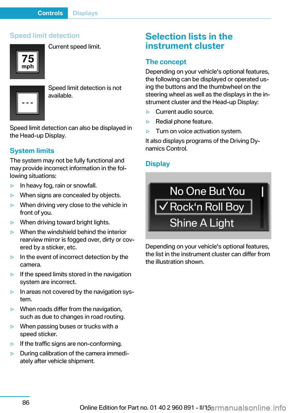
Display
Depending on your vehicle's optional features,
the list in the instrument cluster can differ from
the illustration shown.
Seite 86ControlsDisplays86
Online Edition for Part no. 01 40 2 960 891 - II/15
Page 110 of 224
Malfunction
A Check Control message is displayed.
Variable light distribution is disrupted or failed.
Have the system checked as soon as possible.
High-beam Assistant
The concept When the low beams are activated, this system
automatically switches the high beams on and
off. The procedure is controlled by a camera
on the front of the interior rearview mirror. The assistant ensures that the high beams are acti‐
vated whenever the traffic situation allows. The
driver can intervene at any time and switch the
high beams non and off as usual.
Note Personal responsibility
The High-beam Assistant cannot serve
as a substitute for the driver's personal judg‐
ment of when to use the high beams. There‐
fore, manually reel off the high beams in situa‐
tions where required to avoid a safety risk.◀
Activating1.Depending on the equipment, turn the light
switch into position
or .
2.Press button on the turn signal lever, ar‐
row.
The indicator lamp in the instrument
cluster lights up.
When the low beams are on, the lights are au‐
tomatically brightened or dimmed.
The system responds to light from oncoming
traffic and traffic driving ahead of you, and to
adequate illumination, e.g., in towns and cities.
The blue indicator lamp in the instru‐
ment cluster lights up when the system
switches on the high beams.
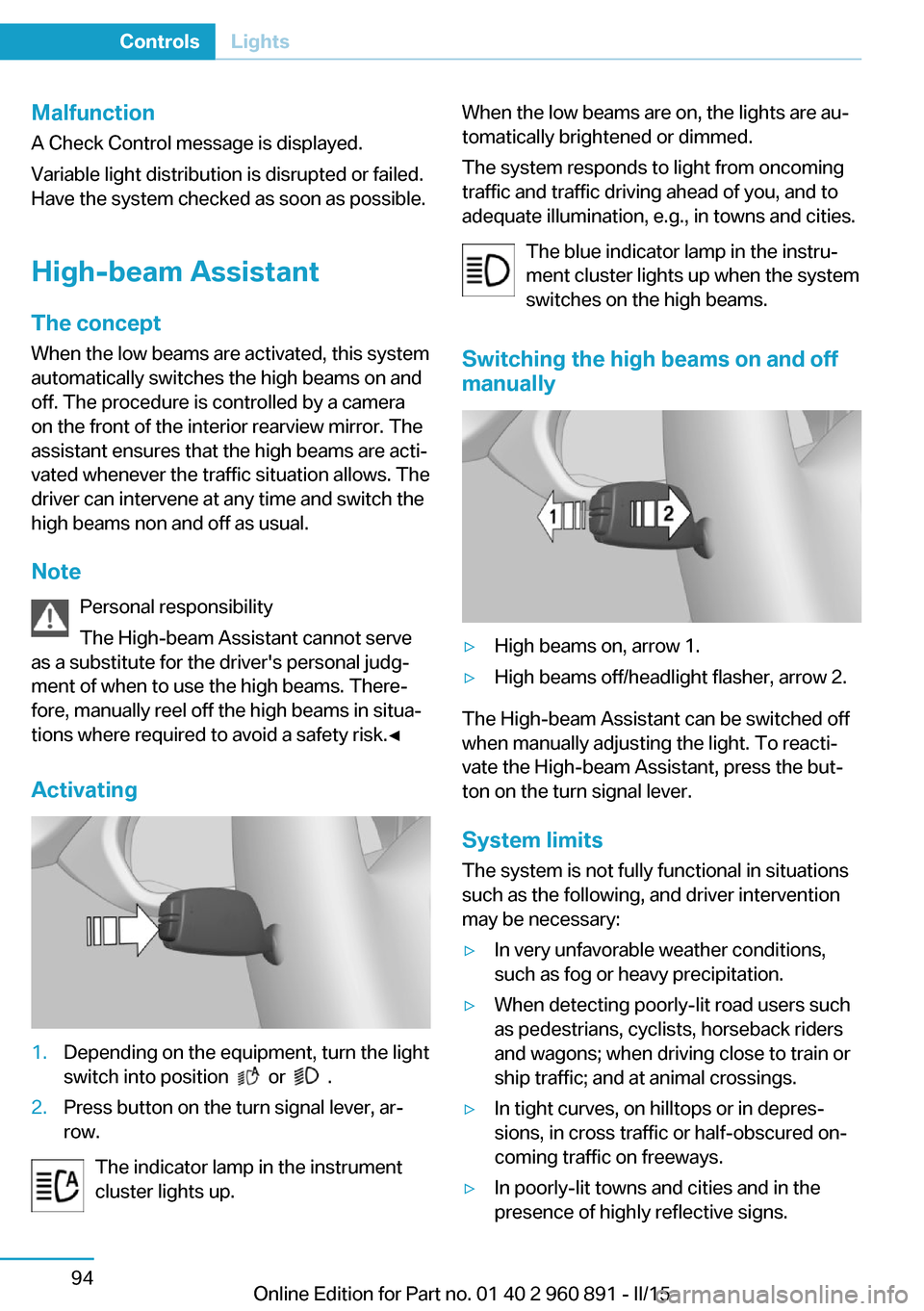
Switching the high beams on and off manually▷High beams on, arrow 1.▷High beams off/headlight flasher, arrow 2.
The High-beam Assistant can be switched off
when manually adjusting the light. To reacti‐
vate the High-beam Assistant, press the but‐
ton on the turn signal lever.
System limits
The system is not fully functional in situations such as the following, and driver intervention
may be necessary:
▷In very unfavorable weather conditions,
such as fog or heavy precipitation.▷When detecting poorly-lit road users such
as pedestrians, cyclists, horseback riders
and wagons; when driving close to train or
ship traffic; and at animal crossings.▷In tight curves, on hilltops or in depres‐
sions, in cross traffic or half-obscured on‐
coming traffic on freeways.▷In poorly-lit towns and cities and in the
presence of highly reflective signs.Seite 94ControlsLights94
Online Edition for Part no. 01 40 2 960 891 - II/15
Page 133 of 224

▷For persons with certain clothing, e.g.
coats.▷With external interference of the ultra‐
sound, e.g. from passing vehicles or loud
machines.▷When sensors are dirty, iced over, dam‐
aged or out of position.▷Under certain weather conditions such as
high relative humidity, rain, snowfall, ex‐
treme heat or strong wind.▷With tow bars and trailer couplings of other
vehicles.▷With thin or wedge-shaped objects.▷With moving objects.▷With elevated, protruding objects such as
ledges or cargo.▷With objects with corners and sharp edges.▷With objects with a fine surface structure
such as fences.▷For objects with porous surfaces.
Low objects already displayed, e.g., curbs, can
move into the blind area of the sensors before
or after a continuous tone sounds.
False warnings
PDC may issue a warning under the following conditions even though there is no obstacle
within the detection range:
▷In heavy rain.▷When sensors are very dirty or covered
with ice.▷When sensors are covered in snow.▷On rough road surfaces.▷On uneven surfaces, such as speed
bumps.▷In large buildings with right angles and
smooth walls, e.g., in underground ga‐
rages.▷In automatic car washes.▷Through heavy pollution.▷Due to other ultrasound sources, e.g.,
sweeping machines, high pressure steam
cleaners or neon lights.
Malfunction
A Check Control message is displayed.
Red symbol is displayed, and the range
of the sensors is dimmed on the Con‐
trol Display.
PDC has failed. Have the system checked.
To ensure full functionality:
▷Keep the sensors clean and free of ice.▷dimmedDo not put any stickers on sen‐
sors.▷When using high-pressure washers, do not
spray the sensors for long periods and
maintain a distance of at least 12 in/30 cm.
Surround View
The concept Surround View comprises various camera as‐
sistance systems that help the driver when
parking, maneuvering, and at complex exits
and intersections.
▷Rearview camera, refer to page 117▷Top View, refer to page 120.▷Side View, refer to page 122.
Rearview camera
The concept The rearview camera provides assistance in
parking and maneuvering backwards. The area
behind the vehicle is shown on the Control
Display.
Seite 117Driving comfortControls117
Online Edition for Part no. 01 40 2 960 891 - II/15
Page 150 of 224
Storage compartmentsVehicle features and optionsThis chapter describes all standard, country-
specific and optional features offered with the
series. It also describes features that are not
necessarily available in your car, e. g., due to
the selected options or country versions. This
also applies to safety-related functions and
systems. The respectively applicable country
provisions must be observed when using the
respective features and systems.
Hints No loose objects in the car's interior
Do not stow any objects in the car's inte‐
rior without securing them; otherwise, they
may present a danger to occupants e.g., during
braking and evasive maneuvers.◀
Do not place anti-slip mats on the dash‐
board
Do not place anti-slip mats on the dashboard.
The mat materials could damage the dash‐
board.◀
Storage compartments The following storage compartments are avail‐
able in the vehicle interior:▷Glove compartment on the front passenger
side, refer to page 134.▷Between the front seats, refer to
page 134.▷Rear seat, refer to page 135.Glove compartment
Front passenger side
Note Close the glove compartment again im‐
mediately
Close the glove compartment immediately af‐
ter use while driving; otherwise, injury may oc‐
cur during accidents.◀
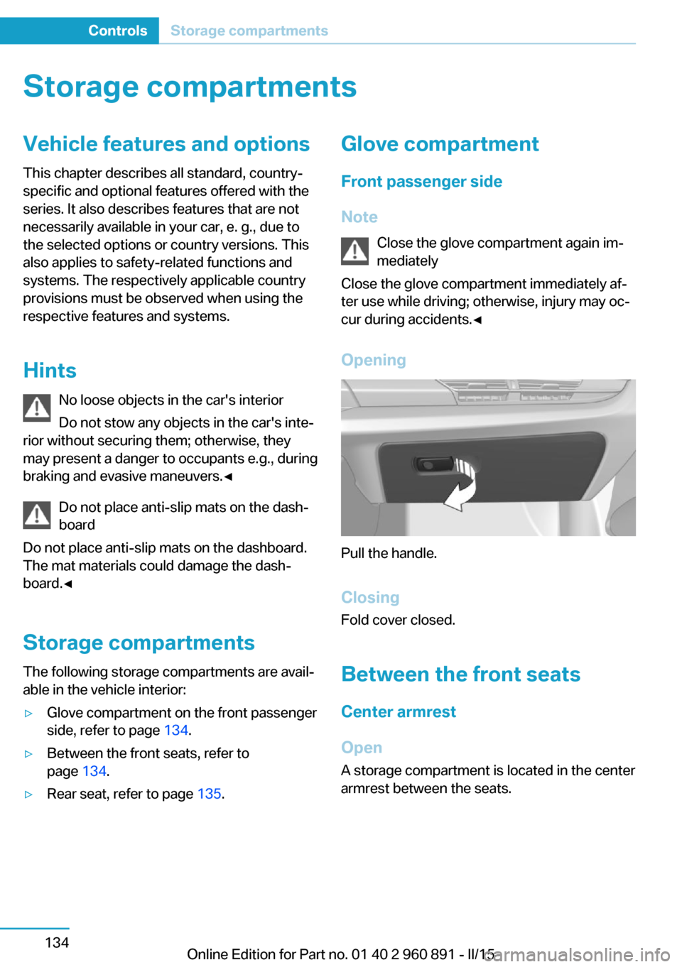
Opening
Pull the handle.
ClosingFold cover closed.
Between the front seats
Center armrest
Open A storage compartment is located in the center
armrest between the seats.
Seite 134ControlsStorage compartments134
Online Edition for Part no. 01 40 2 960 891 - II/15
Page 158 of 224
LoadingVehicle features and options
This chapter describes all standard, country-
specific and optional features offered with the
series. It also describes features that are not
necessarily available in your car, e. g., due to
the selected options or country versions. This
also applies to safety-related functions and
systems. The respectively applicable country
provisions must be observed when using the
respective features and systems.
Hints Overloading the vehicle
To avoid exceeding the approved ca‐
pacity of the tires, never overload the vehicle.
Overloading can lead to overheating and in‐
creases the rate at which damage develops in‐
side the tires. This could result in a sudden
loss of tire inflation pressure.◀
No fluids in the cargo area
Make sure that fluids do not leak into the
cargo area; otherwise, the vehicle may be dam‐
aged.◀
Heavy and hard objects
Do not stow any heavy and hard objects
in the car's interior without securing them; oth‐
erwise, they may present a danger to occu‐
pants, e.g., during braking and evasive maneu‐
vers.◀
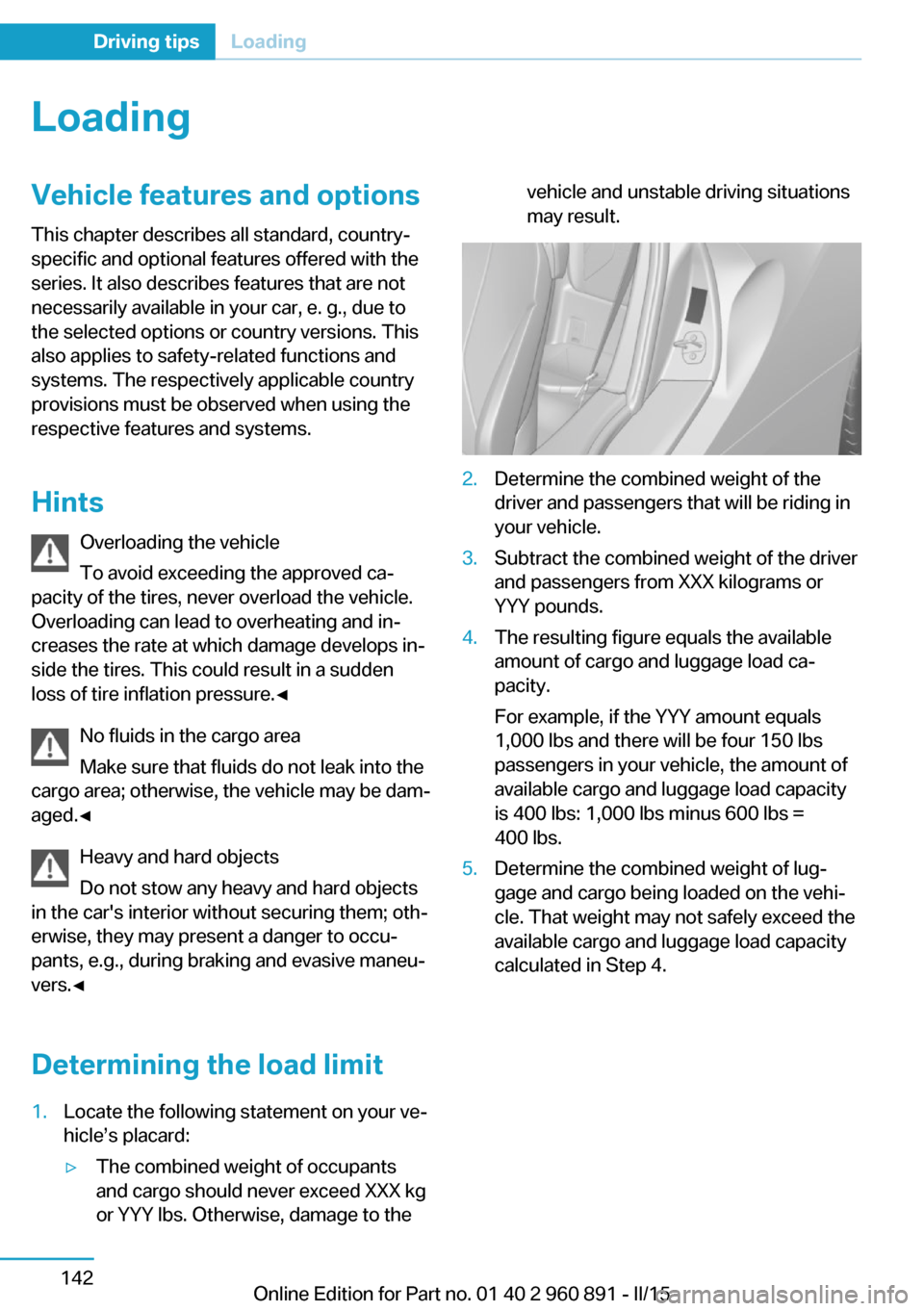
Determining the load limit1.Locate the following statement on your ve‐
hicle’s placard:▷The combined weight of occupants
and cargo should never exceed XXX kg
or YYY lbs. Otherwise, damage to thevehicle and unstable driving situations
may result.2.Determine the combined weight of the
driver and passengers that will be riding in
your vehicle.3.Subtract the combined weight of the driver
and passengers from XXX kilograms or
YYY pounds.4.The resulting figure equals the available
amount of cargo and luggage load ca‐
pacity.
For example, if the YYY amount equals
1,000 lbs and there will be four 150 lbs
passengers in your vehicle, the amount of
available cargo and luggage load capacity
is 400 lbs: 1,000 lbs minus 600 lbs =
400 lbs.5.Determine the combined weight of lug‐
gage and cargo being loaded on the vehi‐
cle. That weight may not safely exceed the
available cargo and luggage load capacity
calculated in Step 4.Seite 142Driving tipsLoading142
Online Edition for Part no. 01 40 2 960 891 - II/15