2015 BMW I8 remote start
[x] Cancel search: remote startPage 55 of 224

Replacing the battery1.Remove integrated key from remote con‐
trol.2.Raise the cover of the battery compart‐
ment, arrow 1.3.Remove the cover of the battery compart‐
ment, arrow 2.4.Insert a battery of the same type with the
positive side facing up.5.Press the cover closed.
Take the used battery to a recycling
center or to your service center.
New remote controls New remote controls are available from the
service center.
Loss of the remote controls Lost remote controls can be disabled by your
service center.
Emergency detection of remote
control
Also in the following situations, radio-ready
state and drive readiness can be established:
▷Interference of radio transmission to re‐
mote control by external sources e.g., by
radio masts.▷Empty battery in remote control.▷Interference from radio transmissions
through mobile devices in close proximity
to remote control.▷Interference of radio transmission by
charger while charging items such as mo‐
bile devices in the vehicle.
A Check Control message is displayed if one
attempts to turn on the radio-ready state or ac‐
tivate engine readiness.
Activation of drive readiness via
emergency detection of the remote
control
If a respective Check Control message ap‐
pears, hold the remote control with its back
against the marked area on the steering col‐
umn. The BMW logo on the remote control
should be at the same height as the marked
area. Press the Start/Stop button within
10 seconds while pressing the brake pedal.
If the remote control is not recognized: slightly
change the height position of the remote con‐
trol and repeat the procedure.
Personal Profile
The concept Personal Profile provides three profiles, using
which personal vehicle settings can be stored.
Every remote control has one of these profiles
assigned.
If the vehicle is unlocked using a remote con‐
trol, the assigned personal profile will be acti‐
vated. All settings stored in the profile are au‐
tomatically applied.
If several drivers use their own remote control,
the vehicle will adjust the personal settings
Seite 39Opening and closingControls39
Online Edition for Part no. 01 40 2 960 891 - II/15
Page 57 of 224
3."Export profile"4.BMW Online: "BMW Online"
USB interface: "USB device"
Alternatively, the settings and contacts can be
exported via an app to a suitable smartphone.
Importing profiles Profiles exported via BMW Online can also be
imported via BMW Online.
Profiles stored on a USB device can be im‐
ported via the USB interface.
Existing settings are overwritten with the im‐
ported profile.
1."Settings"2."Profiles"3."Import profile"4.BMW Online: "BMW Online"
USB interface: "USB device"
Alternatively, the settings and contacts can be
imported via an app from a suitable smart‐
phone.
Using the guest profile The guest profile is for individual settings that
are saved in none of the three personal pro‐
files.
This can be useful for drivers who are using
the vehicle temporarily and do not have their
own profile.
1."Settings"2."Profiles"3."Guest"
The guest profile cannot be renamed. It is not
assigned to the current remote control.
Display profile list during start
The profile list can be displayed during each
start to select the desired profile.
1."Settings"2."Profiles"3."Options"4."Display user list at startup"
LED in the driver's door
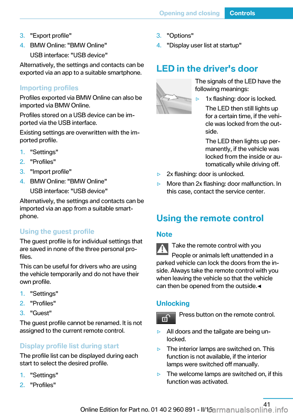
The signals of the LED have the
following meanings:
▷1x flashing: door is locked.
The LED then still lights up
for a certain time, if the vehi‐
cle was locked from the out‐
side.
The LED then lights up per‐
manently, if the vehicle was
locked from the inside or au‐
tomatically while driving off.▷2x flashing: door is unlocked.▷More than 2x flashing: door malfunction. In
this case, contact the service center.
Using the remote control
Note Take the remote control with youPeople or animals left unattended in a
parked vehicle can lock the doors from the in‐
side. Always take the remote control with you
when leaving the vehicle so that the vehicle
can then be opened from the outside.◀
Unlocking Press button on the remote control.
▷All doors and the tailgate are being un‐
locked.▷The interior lamps are switched on. This
function is not available, if the interior
lamps were switched off manually.▷The welcome lamps are switched on, if this
function was activated.Seite 41Opening and closingControls41
Online Edition for Part no. 01 40 2 960 891 - II/15
Page 63 of 224
Tailgate
Depending on optional features and country
version, this setting is not offered in some
cases.1."Settings"2."Doors/key"3. Select the symbol.4.Select the desired function:▷"Tailgate"
The tailgate is unlocked.▷"Tailgate + door(s)"
The tailgate and the doors are un‐
locked.
Confirmation signals from the vehicle
The settings are saved in the active profile, re‐
fer to page 39.
1."Settings"2."Doors/key"3.Deactivate or activate the desired confir‐
mation signals.▷"Acoustic sig. lock/unlock"▷"Flash when lock/unlock"
Automatic locking
The settings are saved in the active profile, re‐fer to page 39.
1."Settings"2."Doors/key"3.Select the desired function:▷"Lock if no door is opened"
The vehicle locks automatically after a
short period of time if no door is
opened.▷"Lock after start driving"
The vehicle locks automatically after
you drive off.Without alarm system: headlamp
courtesy delay feature/standing
climate control
The settings are saved in the active profile, re‐
fer to page 39.1."Settings"2."Doors/key"3. Select the symbol.4.Select the desired function:▷"Pathway lighting"
Headlight courtesy delay feature▷"Comfort climate control"
Stationary climate control
Alarm system
The conceptWhen the vehicle is locked, the vehicle alarm
system responds to:
▷Opening a door, the hood or the tailgate.▷Movements in the interior.▷Changes in the vehicle tilt, e. g., during at‐
tempts at stealing a wheel.▷Disconnected battery voltage.
The alarm system briefly signals tampering:
▷By sounding an acoustic alarm.▷By switching on the hazard warning sys‐
tem.▷By flashing the high beams.
Arming and disarming the alarm
system
When you unlock or lock the vehicle, either
with the remote control or via the Comfort Ac‐
cess, the alarm system is disarmed or armed at
the same time.
Seite 47Opening and closingControls47
Online Edition for Part no. 01 40 2 960 891 - II/15
Page 82 of 224
Energy recovery: CHARGEThe high-voltage battery is recharged in part
through energy recovery. The electric motor
acts as a generator when decelerating and
converts the kinetic energy into electrical en‐
ergy.
Energy can be recovered if the following condi‐
tions are met:▷The vehicle is moving.▷Speed higher than approx.
12 mph/20 km/h.▷Selector lever in selector lever position D,
R or S.▷The high-voltage battery is not fully
charged.▷Accelerator pedal is not operated.
Energy cannot be recovered in the following
situations:
▷Selector lever position N is set.▷While drive stability control systems con‐
trol the vehicle, even though it is not indi‐
cated by an indicator light.▷The high-voltage battery is fully charged.▷When temperature of the high-voltage bat‐
tery is very low or very high.
With cold external temperatures, it is pos‐
sible that the energy recovery is tempora‐
rily unavailable after startup.
Parking brake
The concept The parking brake is used to prevent the vehi‐
cle from rolling when it is parked.
Overview
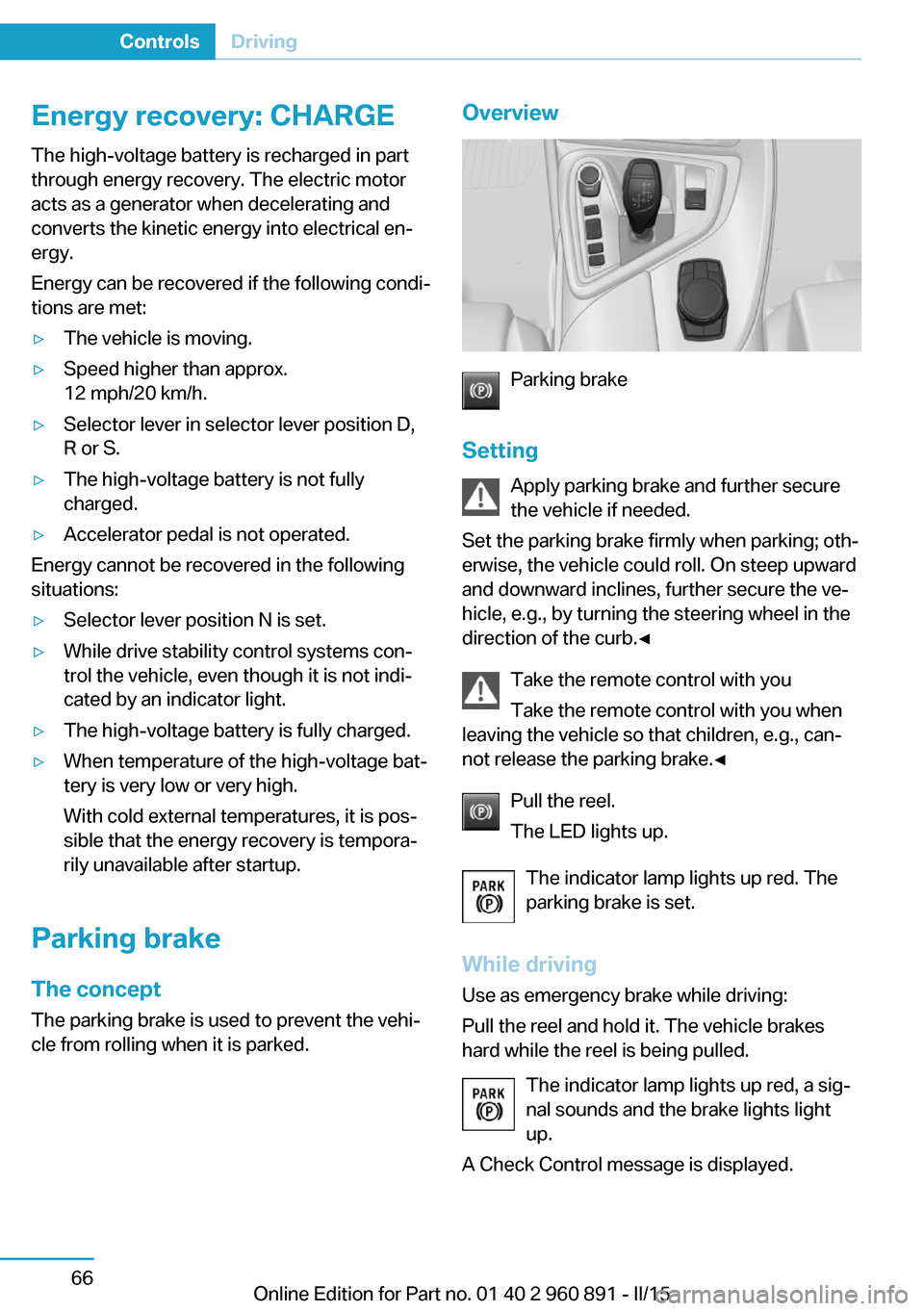
Parking brake
Setting Apply parking brake and further secure
the vehicle if needed.
Set the parking brake firmly when parking; oth‐
erwise, the vehicle could roll. On steep upward
and downward inclines, further secure the ve‐
hicle, e.g., by turning the steering wheel in the
direction of the curb.◀
Take the remote control with youTake the remote control with you when
leaving the vehicle so that children, e.g., can‐
not release the parking brake.◀
Pull the reel.
The LED lights up.
The indicator lamp lights up red. The
parking brake is set.
While driving
Use as emergency brake while driving:
Pull the reel and hold it. The vehicle brakes
hard while the reel is being pulled.
The indicator lamp lights up red, a sig‐
nal sounds and the brake lights light
up.
A Check Control message is displayed.
Seite 66ControlsDriving66
Online Edition for Part no. 01 40 2 960 891 - II/15
Page 147 of 224
4.Likewise, press and hold the button of the
desired function on the hand-held trans‐
mitter.5.Release both buttons as soon as the inte‐
rior rearview mirror LED flashes more rap‐
idly. The LED flashing faster indicates that
the button on the interior rearview mirror
has been programmed. The system can
then be controlled by the button on the in‐
terior rearview mirror.
If the LED does not flash faster after at
least 60 seconds, change the distance and
repeat the step. Several more attempts at
different distances may be necessary. Wait
at least 15 seconds between attempts.
Canada: if programming with the hand-
held transmitter was interrupted, hold
down the interior rearview mirror button
and repeatedly press and release the
hand-held transmitter button for 2 sec‐
onds.
Controls
Before operation
Before operating a system using the uni‐
versal garage door opener, ensure that there are no people, animals, or objects within the
range of movement of the remote-controlled
system; otherwise, there is a risk of injury or
damage.
Also follow the safety instructions of the hand-
held transmitter.◀
The system, such as the garage door, can be
operated using the button on the interior rear‐
view mirror while the engine is running or when
the ignition is started. To do this, hold down
the button within receiving range of the system
until the function is activated. The interior rear‐ view mirror LED stays lit while the wireless sig‐
nal is being transmitted.
Deleting stored functions Press and hold the left and right button on the
interior rearview mirror simultaneously for ap‐
proximately 20 seconds until the LED flashes
rapidly. All stored functions are deleted. The
functions cannot be deleted individually.
Sun visor Glare shieldFold the sun visor down or up.
Vanity mirror A vanity mirror is located in the sun visor be‐
hind a cover. When the cover is opened, the
mirror lighting switches on.
Connecting electricaldevices
Hints Do not connect charging devices to the12 volt socket in the vehicle
Do not connect battery chargers to the fac‐
tory-installed 12 volt sockets in the vehicle as
this may damage the vehicle battery due to an
increased power consumption.◀
Replace the cover after use
Reinsert the lighter or socket cover after
use, otherwise objects may get into the lighter
socket or fixture and cause a short circuit.◀
Sockets
General information
The lighter socket can be used as a socket for
electrical equipment while the engine is run‐
ning or when the ignition is switched on.
Note
The total load of all sockets must not exceed 140 watts at 12 volts.
Do not damage the socket by using unsuitable
connectors.Seite 131Interior equipmentControls131
Online Edition for Part no. 01 40 2 960 891 - II/15
Page 170 of 224
4.Connect either a Level 1 or Level 2 charg‐
ing cable to the household socket or the
port on the charging station.5.Open charging port flap.6.Connect charging cable to the vehicle, re‐
fer to page 152.
At high temperatures, initially the high-voltage
battery is cooled. The charging process can be
started with a delay.
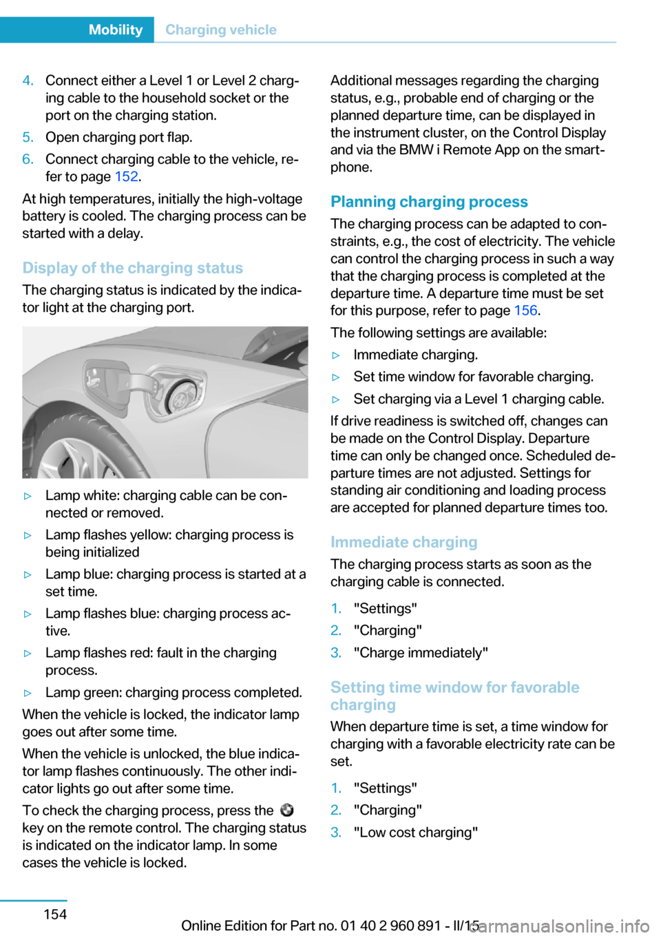
Display of the charging status
The charging status is indicated by the indica‐
tor light at the charging port.
▷Lamp white: charging cable can be con‐
nected or removed.▷Lamp flashes yellow: charging process is
being initialized▷Lamp blue: charging process is started at a
set time.▷Lamp flashes blue: charging process ac‐
tive.▷Lamp flashes red: fault in the charging
process.▷Lamp green: charging process completed.
When the vehicle is locked, the indicator lamp
goes out after some time.
When the vehicle is unlocked, the blue indica‐
tor lamp flashes continuously. The other indi‐
cator lights go out after some time.
To check the charging process, press the
key on the remote control. The charging status
is indicated on the indicator lamp. In some
cases the vehicle is locked.
Additional messages regarding the charging
status, e.g., probable end of charging or the
planned departure time, can be displayed in
the instrument cluster, on the Control Display
and via the BMW i Remote App on the smart‐
phone.
Planning charging process The charging process can be adapted to con‐
straints, e.g., the cost of electricity. The vehicle
can control the charging process in such a way
that the charging process is completed at the
departure time. A departure time must be set
for this purpose, refer to page 156.
The following settings are available:▷Immediate charging.▷Set time window for favorable charging.▷Set charging via a Level 1 charging cable.
If drive readiness is switched off, changes can
be made on the Control Display. Departure
time can only be changed once. Scheduled de‐
parture times are not adjusted. Settings for
standing air conditioning and loading process
are accepted for planned departure times too.
Immediate chargingThe charging process starts as soon as the
charging cable is connected.
1."Settings"2."Charging"3."Charge immediately"
Setting time window for favorable
charging
When departure time is set, a time window for
charging with a favorable electricity rate can be
set.
1."Settings"2."Charging"3."Low cost charging"Seite 154MobilityCharging vehicle154
Online Edition for Part no. 01 40 2 960 891 - II/15
Page 215 of 224

Braking, hints 140
Breakdown assistance 183
Break-in 138
Brightness of Control Dis‐ play 90
Bulb replacement 180
Bulbs and lamps 180
Button, Start/Stop 61
Bypassing, refer to Jump- starting 184
C
California Proposition 65 Warning 8
Camera lenses, care 190
Camera, rearview cam‐ era 118
Camera, Side View 122
Camera, Top View 121
Car battery 181
Car care products 188
Care, displays 190
Care, vehicle 188
Cargo 142
Cargo area 132
Cargo cover 132
Car key, refer to Remote con‐ trol 38
Carpet, care 189
Car wash 187
Catalytic converter, refer to Hot exhaust system 140
CBS Condition Based Serv‐ ice 178
Center armrest 134
Center console 16
Central locking system 44
Central screen, refer to Con‐ trol Display 18
Changes, technical, refer to Safety 7
Changing wheels 181
Changing wheels/tires 167
CHARGE, energy recov‐ ery 66 Charging battery, see Vehicle
charging 150
Charging, refer to Charging vehicle 150
Charging, refer to Vehicle charging 150
Charging screen 76
Charging state indicator, high-voltage battery 77
Charging status, see display of the charging status 154
Charging vehicle 150
Charging vehicle, refer to Ve‐ hicle charging 150
Chassis number, see vehicle identification number 10
Check Control 79
Checking the engine oil level electronically 173
Checking the oil level elec‐ tronically 173
Children, seating position 57
Children, transporting safely 57
Child restraint fixing sys‐ tem 57
Child restraint fixing system LATCH 58
Child restraint fixing systems, mounting 57
Child seat, mounting 57
Child seats 57
Chrome parts, care 189
Cleaning displays 190
Climate control 124
Clock 83
Closing/opening via door lock 43
Closing/opening with remote control 41
Combination reel, refer to Turn signals 67
Combination switch, refer to Wiper system 68
Combustion engine, start‐ ing 63 Comfort Access 45
COMFORT program, Dy‐ namic Driving Control 111
Compressor 168
Computer, refer to On-board computer 87
Condensation on win‐ dows 127
Condensation under the vehi‐ cle 141
Condition Based Service CBS 178
Confirmation signal 47
ConnectedDrive 6
ConnectedDrive Services 6
Connecting electrical devi‐ ces 131
Contact with water, high-volt‐ age system 34
Control Display 18
Control Display, settings 89
Controller 18
Control systems, driving sta‐ bility 109
Convenient opening with the remote control 42
Coolant 177
Coolant temperature 83
Cooling function 125
Cooling, maximum 125
Cooling system 177
Corrosion on brake discs 141
Cosmetic mirror 131
Courtesy lamps during un‐ locking 41
Courtesy lamps with the vehi‐ cle locked 42
Cruise control 113
Cruising range 83
Current fuel consumption 87
D
Damage, tires 166
Data, technical 194
Date 83 Seite 199Everything from A to ZReference199
Online Edition for Part no. 01 40 2 960 891 - II/15
Page 216 of 224

Daytime running lights 93
Deactivating drive readi‐ ness 63
Defrosting, refer to Windows, defrosting 127
Dehumidifying, air 125
Deleting personal data 24
Deletion of personal data 24
Departure times, stationary climate control 128
Destination distance 88
Digital clock 83
Dimensions 194
Dimmable exterior mirrors 55
Dimmable interior rearview mirror 55
Direction indicator, refer to Turn signals 67
Display in windshield 90
Display lighting, refer to In‐ strument lighting 95
Displays 75
Displays, cleaning 190
Displays, hybrid system 77
Disposal, vehicle battery 182
Distance control, refer to PDC 115
Distance to destination 88
Divided screen view, split screen 23
Door lock 43
Door lock, refer to Remote control 38
Drive-off assistant 112
Drive-off assistant, refer to DSC 109
Driver's door, LED 41
Drive readiness 61
Drive readiness in detail 62
Drive readuness, deacti‐ vate 63
Driving Dynamics Con‐ trol 111
Driving instructions, break- in 138 Driving instructions, eDRIVE
drive system 138
Driving mode 111
Driving notes, general 139
Driving stability control sys‐ tems 109
Driving tips 139
Driving with combustion en‐ gine, POWER 65
DSC Dynamic Stability Con‐ trol 109
DTC Dynamic Traction Con‐ trol 110
Dynamic Stability Control DSC 109
Dynamic Traction Control DTC 110
E
eBOOST 65
ECO PRO 145
ECO PRO display 145
ECO PRO driving mode 145
ECO PRO mode 145
ECO PRO Tip - driving in‐ struction 146
eDRIVE drive system, driving instructions 138
eDRIVE, electric driving, see BMW eDRIVE 32
eDrive system, at a glance 31
EfficientDynamics 146
Electric drive readiness, Si‐ lent Start 63
Electric driving, ePOWER 64
Electric driving, max eDRIVE 64
Electric driving, see BMW eDRIVE 32
Electronic oil measure‐ ment 173
Electronic Stability Program ESP, refer to DSC 109
Emergency charging, refer to Backup charging 156 Emergency detection, remote
control 39
Emergency release, fuel filler flap 159
Emergency Request 183
Emergency start function, en‐ gine start 39
Emergency unlocking, tail‐ gate 45
Emergency unlocking, trans‐ mission lock 73
Energy Control 87
Energy recovery, CHARGE 66
Engine coolant 177
Engine noise, artificial 65
Engine oil 173
Engine oil, adding 175
Engine oil additives 175
Engine oil change 176
Engine oil filler neck 175
Engine oil temperature 83
Engine oil types, alterna‐ tive 176
Engine oil types, ap‐ proved 175
Engine start during malfunc‐ tion 39
Engine start, jump-start‐ ing 184
Engine temperature 83
Entering a car wash 187
ePOWER, electric driving 64
Equipment, interior 129
Error displays, see Check Control 79
ESP Electronic Stability Pro‐ gram, refer to DSC 109
Exchanging wheels/tires 167
Exhaust system 140
Exterior mirror, automatic dimming feature 55
Exterior mirrors 54
External start 184
External temperature dis‐ play 83 Seite 200ReferenceEverything from A to Z200
Online Edition for Part no. 01 40 2 960 891 - II/15