2015 BMW 5 SERIES GRAN TURISMO Blind
[x] Cancel search: BlindPage 129 of 263
▷If the driving stability control systems are
deactivated, e.g. DSC OFF.▷If the camera viewing field or the front
windshield are dirty or covered.▷Up to 10 seconds after the start of the en‐
gine, via the Start/Stop knob.▷During calibration of the camera immedi‐
ately after vehicle shipment.▷If there is constant blinding effects be‐
cause of oncoming light, e. g., from the sun
low in the sky.▷When it is dark outside.
Night Vision with Pedestrian
and Animal Detection
The concept Night Vision with pedestrian and animal detec‐
tion is a night vision system.
An infrared camera scans the area in front of
the vehicle and issues a warning if it detects
pedestrians and animals on the street. Warm
objects that are similar in shape to human be‐
ings or animals are detected by the system. If necessary, the heat image can be displayed on
the Control Display.
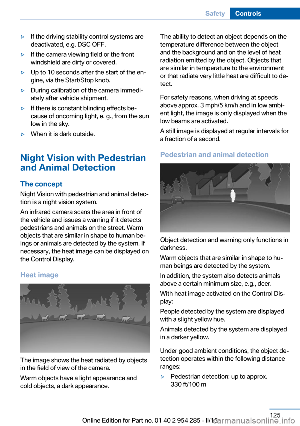
Heat image
The image shows the heat radiated by objects
in the field of view of the camera.
Warm objects have a light appearance and
cold objects, a dark appearance.
The ability to detect an object depends on the
temperature difference between the object
and the background and on the level of heat
radiation emitted by the object. Objects that
are similar in temperature to the environment
or that radiate very little heat are difficult to de‐
tect.
For safety reasons, when driving at speeds
above approx. 3 mph/5 km/h and in low ambi‐
ent light, the image is only displayed when the
low beams are activated.
A still image is displayed at regular intervals for
a fraction of a second.
Pedestrian and animal detection
Object detection and warning only functions in
darkness.
Warm objects that are similar in shape to hu‐
man beings are detected by the system.
In addition, the system also detects animals
above a certain minimum size, e.g., deer.
With heat image activated on the Control Dis‐
play:
People detected by the system are displayed
with a slight yellow hue.
Animals detected by the system are displayed
in a darker yellow.
Under good ambient conditions, the object de‐
tection operates within the following distance
ranges:
▷Pedestrian detection: up to approx.
330 ft/100 mSeite 125SafetyControls125
Online Edition for Part no. 01 40 2 954 285 - II/15
Page 134 of 263
Active Blind Spot Detection
The concept
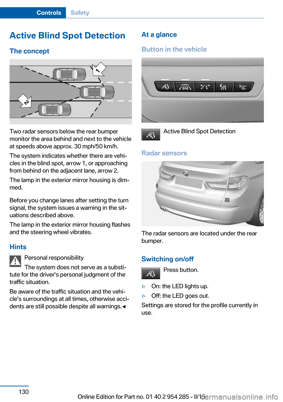
Two radar sensors below the rear bumper
monitor the area behind and next to the vehicle
at speeds above approx. 30 mph/50 km/h.
The system indicates whether there are vehi‐
cles in the blind spot, arrow 1, or approaching
from behind on the adjacent lane, arrow 2.
The lamp in the exterior mirror housing is dim‐
med.
Before you change lanes after setting the turn
signal, the system issues a warning in the sit‐
uations described above.
The lamp in the exterior mirror housing flashes
and the steering wheel vibrates.
Hints Personal responsibility
The system does not serve as a substi‐
tute for the driver's personal judgment of the
traffic situation.
Be aware of the traffic situation and the vehi‐
cle's surroundings at all times, otherwise acci‐
dents are still possible despite all warnings.◀
At a glance
Button in the vehicle
Active Blind Spot Detection
Radar sensors
The radar sensors are located under the rear
bumper.
Switching on/off Press button.
▷On: the LED lights up.▷Off: the LED goes out.
Settings are stored for the profile currently in
use.
Seite 130ControlsSafety130
Online Edition for Part no. 01 40 2 954 285 - II/15
Page 135 of 263
Display
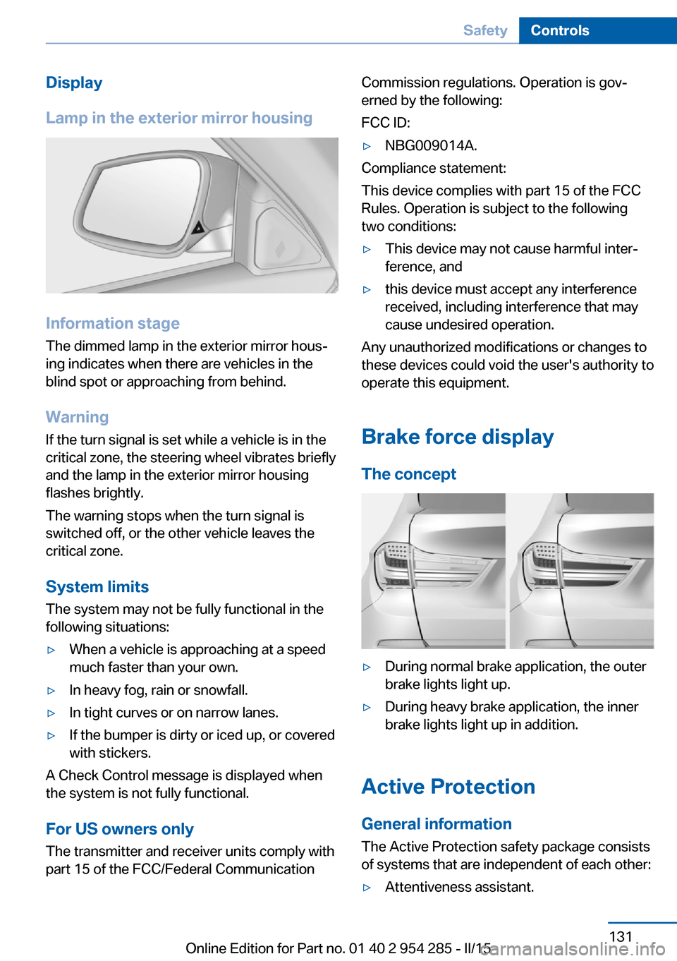
Lamp in the exterior mirror housing
Information stage
The dimmed lamp in the exterior mirror hous‐
ing indicates when there are vehicles in the
blind spot or approaching from behind.
Warning If the turn signal is set while a vehicle is in the
critical zone, the steering wheel vibrates briefly
and the lamp in the exterior mirror housing
flashes brightly.
The warning stops when the turn signal is
switched off, or the other vehicle leaves the
critical zone.
System limits
The system may not be fully functional in the
following situations:
▷When a vehicle is approaching at a speed
much faster than your own.▷In heavy fog, rain or snowfall.▷In tight curves or on narrow lanes.▷If the bumper is dirty or iced up, or covered
with stickers.
A Check Control message is displayed when
the system is not fully functional.
For US owners only The transmitter and receiver units comply with
part 15 of the FCC/Federal Communication
Commission regulations. Operation is gov‐
erned by the following:
FCC ID:▷NBG009014A.
Compliance statement:
This device complies with part 15 of the FCC
Rules. Operation is subject to the following
two conditions:
▷This device may not cause harmful inter‐
ference, and▷this device must accept any interference
received, including interference that may
cause undesired operation.
Any unauthorized modifications or changes to
these devices could void the user's authority to
operate this equipment.
Brake force display
The concept
▷During normal brake application, the outer
brake lights light up.▷During heavy brake application, the inner
brake lights light up in addition.
Active Protection
General information
The Active Protection safety package consists
of systems that are independent of each other:
▷Attentiveness assistant.Seite 131SafetyControls131
Online Edition for Part no. 01 40 2 954 285 - II/15
Page 157 of 263
Low objects already displayed, e.g., curbs, can
move into the blind area of the sensors before
or after a continuous tone sounds.
False warnings
PDC may issue a warning under the following conditions even though there is no obstacle
within the detection range:▷In heavy rain.▷When sensors are very dirty or covered
with ice.▷When sensors are covered in snow.▷On rough road surfaces.▷On uneven surfaces, such as speed
bumps.▷In large buildings with right angles and
smooth walls, e.g., in underground ga‐
rages.▷In automatic car washes.▷Through heavy pollution.▷Due to other ultrasound sources, e.g.,
sweeping machines, high pressure steam
cleaners or neon lights.
Malfunction
A Check Control message is displayed.
The range of the sensors is shown as a shaded
area on the Control Display.
PDC has failed. Have the system checked.
To ensure full functionality:
▷Keep the sensors clean and free of ice.▷dimmedDo not put any stickers on sen‐
sors.▷When using high-pressure washers, do not
spray the sensors for long periods and
maintain a distance of at least 12 in/30 cm.Surround View
The concept Surround View comprises various camera as‐
sistance systems that help the driver when
parking, maneuvering, and at complex exits
and intersections.▷Rearview camera, refer to page 153▷Side View, refer to page 156.▷Top View, refer to page 157.
Rearview camera
The concept The rearview camera provides assistance in
parking and maneuvering backwards. The area
behind the vehicle is shown on the Control
Display.
Hints Check the traffic situation as well
Check the traffic situation around the ve‐
hicle with your own eyes. Otherwise, an acci‐
dent could result from road users or objects
that are not lidtured by the camera.◀
At a glance
Button in the vehicle
Rearview camera
Seite 153Driving comfortControls153
Online Edition for Part no. 01 40 2 954 285 - II/15
Page 160 of 263
System limits
Detection of objects
Very low obstacles as well as high, protruding
objects such as ledges may not be detected by
the system.
Assistance functions also take into account
data of the PDC.
Follow instructions in the PDC chapter, refer to
page 151.
The objects displayed on the Control Display
under certain circumstances are closer than
they appear. Do not estimate the distance from
the objects on the display.
Side View The concept Side View provides an early look at cross traffic
at blind driveways and intersections. Road
users concealed by obstacles to the left and
right of the vehicle can only be detected rela‐
tively late from the driver's seat. To improve
visibility, two cameras in the front of the vehi‐
cle record the traffic situation on each side.
Hints
The images from both cameras are shown si‐
multaneously on the Control Display.
Check the traffic situation as well
Check the traffic situation around the ve‐
hicle on blind driveways and intersections with
your own eyes. Otherwise, an accident could
result from road users or objects located out‐
side the picture area of the Side View cam‐
eras.◀At a glance
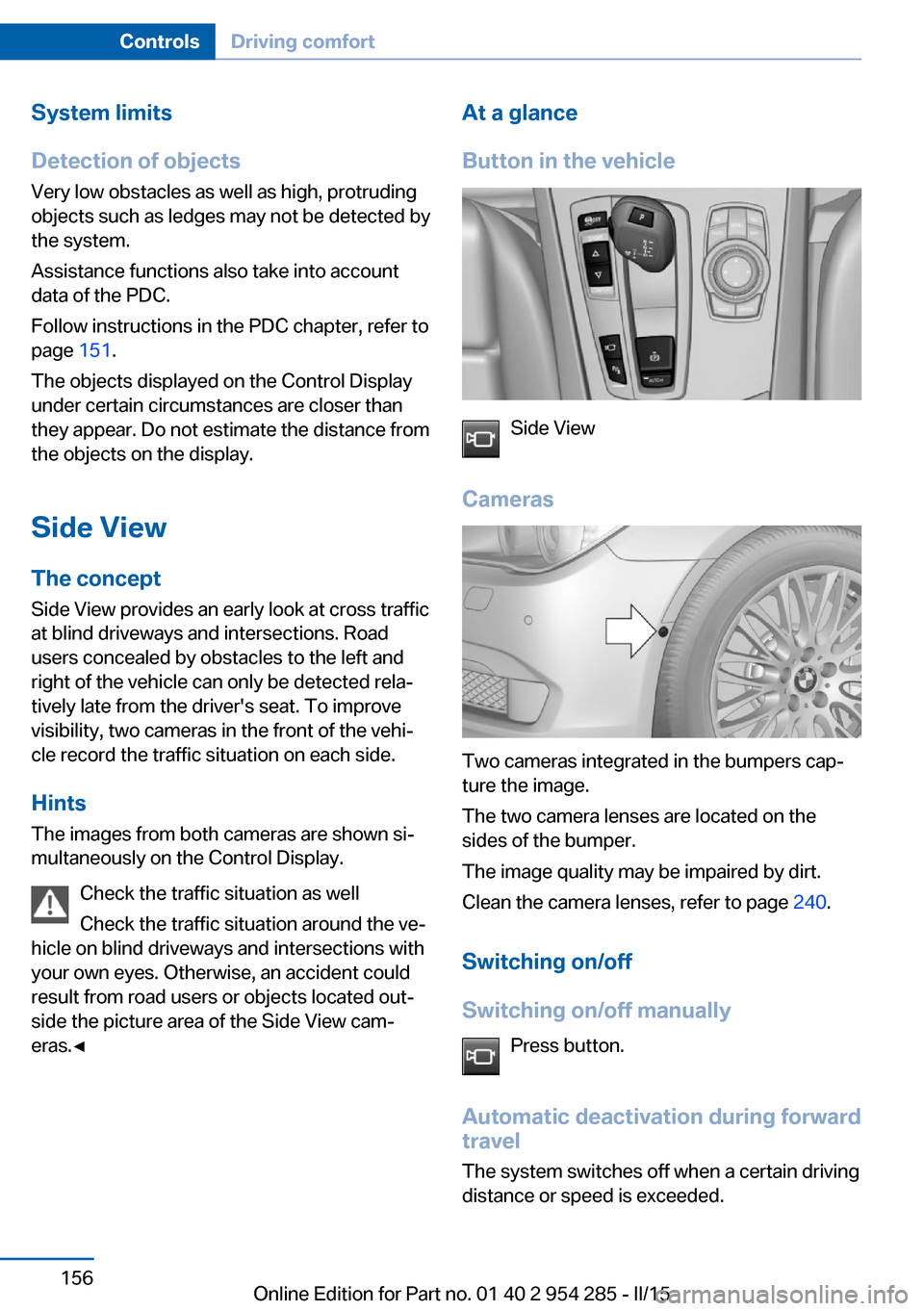
Button in the vehicle
Side View
Cameras
Two cameras integrated in the bumpers cap‐
ture the image.
The two camera lenses are located on the
sides of the bumper.
The image quality may be impaired by dirt.
Clean the camera lenses, refer to page 240.
Switching on/off
Switching on/off manually Press button.
Automatic deactivation during forward travel
The system switches off when a certain driving
distance or speed is exceeded.
Seite 156ControlsDriving comfort156
Online Edition for Part no. 01 40 2 954 285 - II/15
Page 166 of 263
▷Possible on snow-covered or slippery road
surfaces.▷When there are obstacles that are hard to
overcome, such as curbs.▷When there are obstacles that suddenly
arise.▷If the Park Distance Control PDC displays
clearances that are too small.▷If a maximum number of parking attempts
or the time taken for parking is exceeded.▷If a turn signal has been actuated contrary
to the desired side for parking.▷When switching to another function on the
Control Display.
A Check Control message is displayed.
Resume An interrupted parking procedure can be con‐
tinued if needed.
Follow the instructions on the Control Display
to do this.
System limits
No parking assistance
The parking assistant does not offer assis‐
tance in the following situations:
▷In tight curves.
Functional limitations
The system may not be fully functional in the
following situations:
▷On bumpy road surfaces such as gravel
roads.▷On slippery ground.▷On steep uphill or downhill grades.▷With accumulations of leaves/snow in the
parking space.
Limits of ultrasonic measurement
Ultrasonic measuring might not function under
the following circumstances:
▷For small children and animals.▷For persons with certain clothing, e.g.
coats.▷With external interference of the ultra‐
sound, e.g. from passing vehicles or loud
machines.▷When sensors are dirty, iced over, dam‐
aged or out of position.▷Under certain weather conditions such as
high relative humidity, rain, snowfall, ex‐
treme heat or strong wind.▷With tow bars and trailer couplings of other
vehicles.▷With thin or wedge-shaped objects.▷With moving objects.▷With elevated, protruding objects such as
ledges or cargo.▷With objects with corners and sharp edges.▷With objects with a fine surface structure
such as fences.▷For objects with porous surfaces.
Low objects already displayed, e.g., curbs, can
move into the blind area of the sensors before
or after a continuous tone sounds.
The parking assistant may identify parking
spaces that are not suitable for parking.
Malfunction
A Check Control message is displayed.
The parking assistant failed. Have the system
checked.
Seite 162ControlsDriving comfort162
Online Edition for Part no. 01 40 2 954 285 - II/15
Page 252 of 263
Everything from A to Z
IndexA ABS, Antilock Brake Sys‐ tem 134
ACC, Active Cruise Control with Stop & Go 142
Accessories and parts 7
Activated-charcoal filter 166
Active Blind Spot Detec‐ tion 130
Active Cruise Control with Stop & Go, ACC 142
Active Protection 131
Active seat, front 57
Active seat ventilation, front 57
Active Steering, integral 138
Adaptive brake assistant 134
Adaptive brake lights, refer to Brake force display 131
Adaptive drive 137
Adaptive Light Control 103
Additives, oil 219
Adjustments, seats/head re‐ straints 54
After washing vehicle 238
Airbags 107
Airbags, indicator/warning light 108
Air circulation, refer to Recir‐ culated-air mode 165
Air, dehumidifying, refer to Cooling function 165
Air distribution, manual 164
Air flow, automatic climate control 164
Air outlets, see ventila‐ tion 166
Air pressure, tires 204
Alarm system 48
Alarm, unintentional 49 All around the center con‐
sole 16
All around the roofliner 17
All around the steering wheel 14
All-season tires, refer to Win‐ ter tires 211
All-wheel-drive 136
Alternating-code hand-held transmitter 171
Alternative oil types 220
Ambient light 106
Animal detection, see Night Vision 125
Antifreeze, washer fluid 80
Antilock Brake System, ABS 134
Anti-slip control, refer to DSC 134
Approved axle load 245
Approved engine oils, see Suitable engine oil
types 220
Armrest, refer to Center arm‐ rest 179
Arrival time 97
Ashtray 172
Assistance when driving off 134
Attentiveness assistant 132
AUTO H button 74
AUTO H button, refer to Au‐ tomatic Hold 74
AUTO intensity 164
Automatic car wash 237
Automatic climate con‐ trol 163
Automatic Cruise Control with Stop & Go 142
Automatic Curb Monitor 64 Automatic deactivation, front-
seat passenger airbags 109
Automatic headlight con‐ trol 103
Automatic Hold 74
Automatic locking 47
Automatic recirculated-air control 165
Automatic Soft Closing, doors 40
Automatic tailgate 41
Automatic transmission, see Steptronic transmission 81
AUTO program, automatic cli‐ mate control 164
AUTO program, intensity 164
Auto Start/Stop function 71
Average fuel consumption 97
Average speed 97
Axle loads, weights 245
B Backrest curvature, refer to Lumbar support 56
Backrest, seats 54
Backrest, width 57
Band-aids, refer to First aid kit 233
Bar for tow-starting/ towing 235
Battery replacement, vehicle battery 230
Battery replacement, vehicle remote control 35
Battery, vehicle 229
Belts, safety belts 59
Beverage holder, cu‐ pholder 180
Blinds, sun protection 50 Seite 248ReferenceEverything from A to Z248
Online Edition for Part no. 01 40 2 954 285 - II/15
Page 259 of 263

Replacement fuse 230
Replacing parts 225
Replacing wheels/tires 210
Reporting safety defects 9
RES button 145
RES button, see Active Cruise Control, ACC 142
RES button, see Cruise con‐ trol 149
Reserve warning, refer to Range 92
Reset, Tire Pressure Monitor TPM 113
Residual heat, automatic cli‐ mate control 166
Retaining straps, securing cargo 190
Retreaded tires 211
Reversing lamp, bulb replace‐ ment 228
Roadside parking lights 103
Roller sunblinds 50
Roll stabilization, refer to Adaptive Drive 137
Roll stabilization, refer to Dy‐ namic Drive 137
RON recommended fuel grade 202
Roofliner 17
Roof load capacity 245
Roof-mounted luggage rack 190
Rope for tow-starting/ towing 235
RSC Run Flat System Com‐ ponent, refer to Run-flat
tires 211
Rubber components, care 239
Run-flat tires 211
S Safe braking 187
Safety 7 Safety belt reminder for driv‐
er's seat and front passen‐
ger seat 60
Safety belts 59
Safety belts, care 240
Safety Package, refer to Ac‐ tive Protection 131
Safety switch, windows 50
Safety systems, airbags 107
Saving fuel 192
Screen, refer to Control Dis‐ play 18
Screwdriver, see Onboard ve‐ hicle tool kit 225
Screw thread, refer to Screw thread for tow fitting, screw
thread for tow fitting 236
Sealant 212
Seat belts, refer to Safety belts 59
Seat heating, front 57
Seat heating, rear 58
Seating position for chil‐ dren 66
Seat, mirror, and steering wheel memory 62
Seats 54
Seats, front 54
Seats, rear 58
Seat ventilation, front 57
Selection list in instrument cluster 96
Selector lever, Steptronic transmission 81
Self-leveling suspension, air suspension 139
Self-leveling suspension, malfunction 139
Sensors, care 240
Service and warranty 8
Service requirements, Condi‐ tion Based Service
CBS 223
Service requirements, dis‐ play 93
Services, ConnectedDrive SET button, see Active Cruise Control, ACC 142
SET button, see Cruise con‐ trol 149
Settings, locking/unlock‐ ing 46
Settings on Control Dis‐ play 98
Settings, storing for seat, mir‐ rors, steering wheel 62
Shift paddles on the steering wheel 82
Shoulder support 57
Side airbags 107
Side View 156
Signaling, horn 14
Signals when unlocking 47
Sitting safely 54
Size 244
Ski and snowboard bag 177
Slide/tilt glass roof 51
Smallest turning radius 244
Small tailgate via remote con‐ trol 38
Smoker's package 172
Snow chains 215
Socket 173
Socket, OBD Onboard Diag‐ nostics 224
SOS button 232
Spare fuse 230
Speaker lighting 106
Specified engine oil types 220
Speed, average 97
Speed limit detection, on- board computer 97
Speed limiter, display 94
Speed Limit Information 94
Speed warning 98
Split screen 23
SPORT+ - program, Dynamic Driving Control 140
Sport displays, torque dis‐ play, performance dis‐
play 98 Seite 255Everything from A to ZReference255
Online Edition for Part no. 01 40 2 954 285 - II/15