2015 AUDI S3 SEDAN weight
[x] Cancel search: weightPage 229 of 282
.&_ WARNING
Please note the important safe
ty precautions regarding tire pressure ¢
page 224 and load
limits¢
page 227.
Tires and vehicle load limits
There are limits to the amount of load or weight that any vehicle
and any tire can carry . A vehicle
that is overloaded will not handle
well and is more difficult to stop .
Overloading can not only lead to
loss of vehicle control, but can al
so damage important parts of the
vehicle and can lead to sudden
tire failure, including a blowout
and sudden deflation that can
cause the vehicle to crash.
Your safety and that of your pas
sengers also depends on making
sure that load limits are not ex ceeded. Vehicle load includes ev
erybody and everything in and on
the vehicle. These load limits are
technically referred to as the vehi cle's
Gro ss Vehicle We ight Rating
("GVWR").
The "GVWR" includes the weight of the basic vehicle, all factory in
stalled accessories, a full tank of
fuel, oil, coolant and other fluids
Tires and wheels
plus maximum load . The maxi
mum load includes the number of
passengers that the vehicle is in
tended to carry ("seating capac i
ty") with an assumed weight of
150 lbs . (68 kg) for each passen
ger at a designated seating posi
tion and the total weight of any luggage in the vehicle . If you tow
a trailer, the weight of the trailer
hitch and the tongue weight of
the loaded trailer must be includ ed as part of the vehicle load.
The
Gross Ax le Weight Rating
("GAWR") is the maximum load
that can be applied at each of the
vehicle's two ax les.
T he fact that there is an upper
limit to your vehicle's Gross Vehi
cle Weight Rating means that the
total weight of whatever is being
carried in the vehic le (inc luding
the weight of a trai ler hitch and
the tongue weight of the loaded
trailer) is limited. The more pas
sengers in the vehicle or passen
gers who are heavier than the
standard we ights assumed mean
that less weight can be carried as luggage.
The Gross Vehicle Weight Rating
and the Gross Axle Weight Rating .,..
227
Page 230 of 282
Tires and wheels
are listed on the safety compli
ance sticker label located on the
driver's side B-pillar
¢ page 224,
fig. 170 .
& WAR NING
-
Overloading a vehicle can cause
loss of vehicle control, a crash
or other acc ident, serious per
sonal injury, and even death.
-Carrying more weight than your vehicle was designed to carry will prevent the vehicle
from handling properly and in crease the risk of the loss of
vehicle control.
-The brakes on a vehicle that
has been overloaded may not
be able to stop the vehicle
within a safe distance .
-Tires on a vehicle that has been overloaded can fail sud
denly, including a blowout and
sudden deflation, causing loss of control and a crash.
-Always make sure that the to tal load being transported -
inc luding the weight of a trail
er hitch and the tongue
weight of a loaded trailer -
does not make the vehicle
heavier than the vehicle's
Gross Vehicle Weight Rating.
228
Determining correct load
limit
Use the example below to calcu
late the total weight of the pas
sengers and luggage or other
things that you plan to transport so that you can make sure that
your vehicle will not be overload
ed.
Step s for Determining Correct
Load Limit
1. Locate the statement "THE
COMBINED WE IGHT OF OCCU
PANTS AND CARGO SHOULD
NEVER EXCEED XXX KG OR XXX
L BS"on your vehicle's placard
(tire inflation pressure label)
¢ page 224, fig . 170 .
2. Determine the combined
weight of the drive r and pas
sengers that will be riding in
your vehic le.
3. Subtract the combined weight of the driver and passengers
from "XXX" kilograms or "XXX"
pounds shown on the sticker
¢ page 224, fig . 170 .
4. The resulting figure equals the
available amount of cargo and luggage load capacity . For ex
ample, if the
"XXX" amount
equals 1400 lbs . and there will ...
Page 231 of 282

M N
0 > co ,...., \!) 1.1'1
1.1'1
1.1'1
,....,
be five 150 lbs. passengers in
your vehicle, the amount of
available cargo and luggage load capacity is 650 lbs.
(1400-750 (5
X 150) = 650
lbs.)
5. Determine the combined weight of luggage and cargo
being loaded on the vehicle.
That weight may not safely
ex
ceed the available cargo and
luggage load capacity calculat
ed in Step 4.
6. If your vehicle will be towing a trailer, load from your trailer
will be transferred to your vehi
cle. Consult this manual to de
termine how this reduces the available cargo and luggage
load capacity of your vehicle.
.,.Check the tire sidewall
(c> page 214, fig. 168) to deter
mine the designated load rating
for a specific tire.
Wheel bolts and rims
Wheel bolts
Wheel bolts must be clean and loosen/tighten
easily.
Rims
Rims with a bolted rim ring* or with bolted wheel
covers* consis t of mul tiple pieces. These compo
nents were bolted together using special bolts
and a special procedure . You must not repair or
disassemble them
Q ,& .
Tires and wheels
A WARNING
Wheel bolts that are tightened or repaired in
correctly can become loose and result in loss
of vehicle control, which increases the risk of
an accident . For the correct tightening specifi
cation, refer to~
page 242, A~er changing a
wheel.
- Always keep the wheel bolts and the threads
in the wheel hub clean and free of grease.
- Only use wheel bolts that fit the rim.
-Always have damaged rims repaired by an
authorized Audi dealer or authorized Audi
Service Facility. Never repair or disassemble
rims yourself, because this increases the risk
of an accident.
Winter tires
Winter tires significantly improve the vehicle's
handling when driving in winter conditions. Be
cause of their construction (width, compound,
tread pattern), summer tires provide less traction on ice and snow.
.. Use winter tires on all four wheels.
.. Only use winter tires that are approved for your
vehicle .
.. Please note that the maximum permitted
speed may be lower with winter tires
Q _& . An
authorized Audi dealer or authorized Audi Serv
ice Facility can inform you about the maximum
permitted speed for your tires.
.. Check the tire pressure after installing wheels
Qpage 224.
The effectiveness of winter tires is reduced great
ly when the tread is worn down to a depth of
0.157 inch (4 mm). The characteristics of winter
tires also decrease greatly as the tire ages, re
gardless of the remaining tread.
A WARNING
-Never drive faster than the maximum per
mitted speed for your tires. This could cause
the tires to heat up too much. This increases
the risk of an accident because it can cause
the tire to burst.
229
Page 258 of 282
Emergency situation s
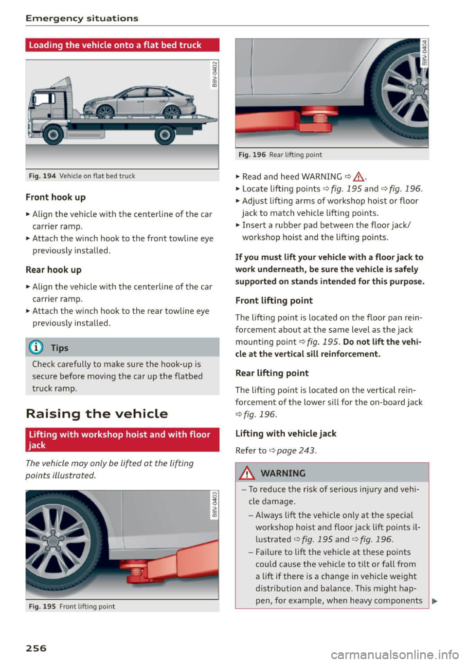
Loading the vehicle onto a flat bed truck
Fig. 194 Ve hicle on flat bed tr uck
Front hook up
.. Align the vehicle w ith the centerline of the car
carrier ramp.
.. Attach the winch hook to the front towline eye
previously installed .
Rear hook up
.. Align the vehicle with the centerline of the car
carr ier ramp .
.. At tach the winch hook to the rear towline eye
previously installed .
@ Tips
Check carefully to make sure the hook-up is
secure before moving the car up the flatbed
truck ramp .
Raising the vehicle
Lifting with workshop hoist and with floor
jack
The vehicle may only be lifted at the lifting
points illustrat ed .
F ig . 19 5 Fron t lifti ng po int
256
Fig . 19 6 Rear lift ing po int
.. Read and heed WARNING ¢ .&, .
.. Locate lifting poi nts ¢ fig . 195 and ¢ fig. 196 .
.. Adjust lifting arms of wo rkshop hoist o r floor
jack to match vehicle lift ing points .
.. Insert a rubbe r pad between the floor jack/
workshop hoist and the lift ing po ints .
If you mu st lift your vehicle with a floor jack to
work underneath, be sure the vehicle is safely
supported on stands intended for this pu rpose .
Front lifting point
The lifti ng point is located o n the floo r pan rein
fo rcement about at the same level as the ja ck
moun ting poin t¢
fig. 195. Do not lift the vehi·
cle at the ve rtical sill reinfor cement.
Rear lifting point
The lifting po int is located o n the vert ica l re in
forcement of the lower s ill for the on -boa rd ja ck
¢ fig . 196.
Lifting with vehicle jack
Refer to ¢ page 243.
,&. WARNING
-To reduce the risk of serious injury and vehi
cle damage.
- Always lift the vehicle only at the specia l
wor kshop hoist and f loor jack lift points il
l ustrated ¢
fig. 195 and¢ fig. 196.
-Fail ure to lift the veh icle at these points
could cause the vehicle to tilt or fall from
a lift if there is a cha nge in vehicle weight
distributi on and balance . This might hap-
pen, for example, when heavy components .,,_
Page 259 of 282

M N
0 > co ,...., \!) 1.1"1
1.1"1
1.1"1
,....,
such as the engine b lock or transmission
are removed .
- When removing heavy components like
these, anchor vehicle to ho ist o r add corre
sponding weights to maintain the center of
gravity . Otherwise, the vehicle might tilt or
s li p off the hoist , causi ng se rious pe rsonal
injury .
([) Note
-Be awa re of the fo llowing points befo re lift
i ng t he ve hicle:
-The vehicle should never be lifted or
jacked up from underneath the engine oil pan, the transmission housing, the front
or rear axle or the body side members.
This could lead to serious damage.
- To avoid damage to the underbody or
chassis frame , a rubber pad must be in·
serted between the floo r jack and the lift
points.
- Before driving over a wo rkshop hoist,
check that the veh icle weight does not
e xceed the permiss ible lift ing capacity of
the hoist.
- Before driv ing over a workshop hoist, en
sure that there is sufficient clearance be
tween the hoist and low parts of the ve
hicle .
Emergency s ituations
257
Page 260 of 282

Technical data
Technical data
Vehicle identification
F ig. 197 Ve hicle Ident if icat ion Number (VlN) p late: loca·
tio n on d river 's side dash pane l
XXXXX XX -X -XX XX XXX XX
@-+ ~J:~t::1 ::: xxxxxxxx xx x xxxx xxx x
IYP lf'VPE XXX X XX
XX XXXXXXX XX X X XX
XXX KW XXX
\YT IM:.COll/fAANS ,COOE XXX XXX 15\_L I MOIOlll
@-+ ~~
1
:tr:~i XXXX I XXXX XXX I XX
II. -AUSST . / OPTIO NS
EO A 7D5 4UB 6X
M SSG SR W
2EH JOZ lLB lAS
1BA
3FC SM U 7 X1
FO A
9G3 O
G7 OY H
OJF
TL 6 3 KA BEH UlA X 9B Q
Z7
l XW
803 908
8Z4 020
7T6 C V7 7 KO 4X3 2K2
3L4 4KC 3YO 413
502
lS A 7GB 01A
4GO
XX X XX X
XX X xxxx
Fig. 198 The ve hicle ide ntif ic ati on label - inside t he lug ·
gage compar tmen t
Vehicle Identificat ion Number (VlN )
The Veh icle Iden tifica tion Number is located in
differen t places :
- u nder the windshield on the driver's side
¢ fig . 197.
- in the MMI: Select: the I MENU I button> Car >
System s* cont ro l button > Service & control >
VIN number .
-on the vehicl e identification label.
258
Vehicle identification label
The vehicle identification label is located i n the
l uggage compartment in the spare whee l we ll.
The label
9 fig . 198 shows the follow ing vehicle
da ta:
(D Vehicle Ident ificat ion Number (VIN)
@ Vehicle type, engine o utput, transmission
@ Engine and transm ission code
@ Pa int number and interior
® Optional equipment numbers
The information of the vehicle identification label
can also be fo und in your Warranty
& Ma inte
nance booklet.
Safety complianc e sticker
The safety compliance sticker is your assurance
that your new vehicle complies with all applicable
Federa l Mo to r Ve hicl e Safety Standards which
were in e ffect at the time the vehicle w as m anu
factured. You can find this sticker on the door
jamb on the d river's s ide. It shows the month and
year of production and the vehicle identification number of your veh icle (perforation) as we ll as
the Gross Veh icle Weight Rating (GVWR) and the
Gross Axle Weight Rating (GAWR).
H igh volt age warning label
The hig h voltage warning label is located i n the
engine compartment next to the engine hood re
l ease. The spark ignition system complies with
the Canadian standard ICES-002 .
Weights
Gross Vehicle Weight Rating
The Gross Vehicle Weight Rating (GVWR), and
the Gross Axle We ight Rating (GAWR) for front
and rear are listed on a st icker on the door jamb
o n the dr iver 's side.
The Gross Vehicle Weight Rating includes the
weight of the basic vehicle plus fu ll fuel tank, oil
and coolant, plus maxim um load, which includes
passenger weight (150 lbs/68 kg per designated
seat ing pos ition) and luggage weight ¢,&. . ..,_
Page 261 of 282
M N
0 > co ,...., \!) ..,.,
..,.,
..,., ,....,
Gross Axle We ight R atin g
The G ross Axle Weight Rating is the maximum
l oad that can be applied at each axl e of the vehi
cle ~.& .
Vehicle capacit y weight
The vehicle capac ity we ight (max. load) is listed
e ither on the dr iver's side B-pillar o r inside the
f u el filler flap .
& WARNING
-The actual Gross Axle Weight Rating at the
front and rear ax les should not exceed the
permissible weights, and their combination
must not exceed the Gross Vehicle Weight
Rating.
Dimensions
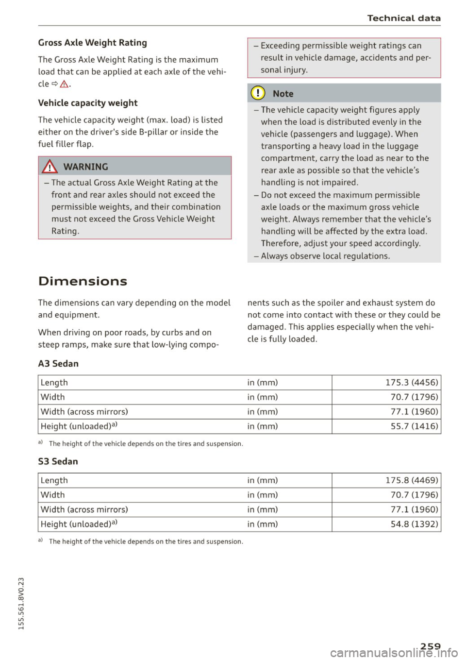
The dimens ions can vary depend ing on the mode l
a nd equipment.
When drivi ng on poor roads, by curbs and on
steep ramps, make sure t hat low -ly ing compo -
A3 Sedan
Length
Wid th
Width (across mir rors)
He ight (unloaded) al
al The he igh t of t he ve hicl e depe nds o n the tir es and s usp en si on .
53 Sedan
Length
Width
Width (across mirrors) He igh t (unloaded) al
al T he heig ht of t he vehi cle dep ends on t he tir es and s uspens ion .
Techni cal data
- Exceeding permiss ible weight ratings can
result in veh icle damage, acc idents and per
sonal injury.
(D Note
- The vehicle capacity weig ht figu res app ly
when the load is d istributed evenly in the
vehicle (passengers and luggage). When
transport ing a heavy load in the luggage
compartment, carry the load as near to the
rear axle as possible so that the vehicle 's
hand ling is not impaired .
- Do not exceed the maximum permissib le
ax le loads or the maximum gross veh icle
we igh t. Always remember that the vehicl e's
hand ling will be affected by the e xtra load.
T herefore, adjus t your speed accordingly.
- Always observe local regulat io ns.
nents such as the spoiler and exhaust system do
not come into contact with these o r they could be
damaged . Th is a pplies es pec ia lly w hen the veh i
cl e is fully loaded.
i n (mm)
1 75 .3 (44 56)
in (mm) 70 .7 (1796)
i n (mm) 77 .1 (1960)
in (mm) 55 .7 (1416)
in (mm) 1 75.8 (4469)
in (mm) 70 .7 (1796)
i n (mm) 77.1 (1960)
in (mm) 54 .8 (1392)
259
Page 273 of 282
M N
0 > co ,...., \!) 1.1"1
1.1"1
1.1"1
,....,
ESC Automatic post-collision braking system 123
Electronic stabilization control . . . . . . . . . 123
Spor t mode . . . . . . . . . . . . . . . . . . . . . . . . 124
also refer to Elec tronic Stabili za tion Control
( E SC) . . . . . . . . . . . . . . . . . . . . . . . . . . . . . . 123
ESP
r e fer to Electronic Stabilization
Control (ESC) . . . . . . . . . . . . . . . . . . . . . . . 123
Event Data Recorder (EDR) . . . . . . . . . . . . . . 122
Exterior lighting . . . . . . . . . . . . . . . . . . . . . . . 43
Exterior mirrors Adjusting . . . . . . . . . . . . . . . . . . . . . . . . . . . 4 7
Dimming ... .. .. ........... .. .. .. .. .. 48
f olding . . . . . . . . . . . . . . . . . . . . . . . . . . . . . 47
Heating . . . . . . . . . . . . . . . . . . . . . . . . . . . . . 47
F
Fastening
Booster seats . . . . . . . . . . . . . . . . . . . . . . . 181
Convertible ch ild safety seats . . . . . . . . . . 179
Infant seats . . . . . . . . . . . . . . . . . . . . . . . . 178
F loor mats . . . . . . . . . . . . . . . . . . . . . . . . . . . 135
F og lights/rear fog light(s) . . . . . . . . . . . . . . . 43
Folding the exterior mirrors Center locking . . . . . . . . . . . . . . . . . . . . . . . 3 7
Folding the rear seats . . . . . . . . . . . . . . . . . . . 60
Foot pedals . . . . . . . . . . . . . . . . . . . . . . . . . . 135
Footwell lighting . . . . . . . . . . . . . . . . . . . . . . 46
F or the sake of the environment
Environmentally-friendly driving . . . . . . . . 70
Fue ling . . . . . . . . . . . . . . . . . . . . . . . . . . . . 192
Leaks . . . . . . . . . . . . . . . . . . . . . . . . . . . . . . 199
Rear window defogger . . . . . . . . . . . . . . . . . 68
Freeze protection
Windshield washer system . . . . . . . . . . . . 212
Fr ont airbags
Description . . . . . . . . . . . . . . . . . . . . . . . . . 152
H ow they work . . . . . . . . . . . . . . . . . . . . . . 158
Frontal collisions and the laws of physics . . 141
Fr ont armrest . . . . . . . . . . . . . . . . . . . . . . . . . 55
Fr ont passenger's door emergency locking . . 39
Front seats Adjusting . . . . . . . . . . . . . . . . . . . . . . . . . . 132
Ch ild restra ints in the front seat . . . . . . . . 149
also refer to Seats . . . . . . . . . . . . . . . . . 53, 60
Index
Fuel
Additives. . . . . . . . . . . . . . . . . . . . . . . . . . . 190
B lended gaso line . . . . . . . . . . . . . . . . . . . . 190
Current consumption . . . . . . . . . . . . . . . . . . 28
Fuel filler neck . . . . . . . . . . . . . . . . . . . . . . 192
Fuel gauge . . . . . . . . . . . . . . . . . . . . . . . 10, 1 1
Fuel tank capacity . . . . . . . . . . . . . . . . . . . 260
Gasoline . . . . . . . . . . . . . . . . . . . . . . . . . . . 190
Gasoline addit ives . . . . . . . . . . . . . . . . . . . 191
Indicator light . . . . . . . . . . . . . . . . . . . . . . . 23
Octane rating . . . . . . . . . . . . . . . . . . . . . . . 190
Recommendation . . . . . . . . . . . . . . . . . . . . 190
Saving fuel . ..... ................ 70, 112
Fuel economy messages (efficiency program)
30
Fueling
Fuel filler door emergency release . . . . . . 194
Fuel gauge .. .. .. ..... ........... ... . 11
Fuel tank capacity . . . . . . . . . . . . . . . . . . . 260
Open ing the fuel filler door . . . . . . . . . . . . 192
Fuses Ass ignment . . . . . . . . . . . . . . . . . . . . . . . . 249
Interior . . . . . . . . . . . . . . . . . . . . . . . . . . . . 248
replacing . . . . . . . . . . . . . . . . . . . . . . . . . . . 248
G
Garment hooks . . . . . . . . . . . . . . . . . . . . . . . . 59
Gas discharge lamps . . . . . . . . . . . . . . . . . . . 250
G lossary of tire and loading terminology . . 216
Glove compartment . . . . . . . . . . . . . . . . . . . . 58
CD changer . . . . . . . . . . . . . . . . . . . . . . . . . . 58
Gross Vehicle Weight Rating (GVWR) . . . . . 258
H
Head light range control system . . . . . . . . . . 43
Indicator light . . . . . . . . . . . . . . . . . . . . . . . 24
Headlights . . . . . . . . . . . . . . . . . . . . . . . . 43, 45
Cleaning . . . . . . . . . . . . . . . . . . . . . . . . . . . 236
Headl ight range control system . . . . . . . . . 43
Left hand drive, right hand drive . . . . . . . . . 46
T rave l mode . . . . . . . . . . . . . . . . . . . . . . . . . 46
Washer system . . . . . . . . . . . . . . . . . . . . . . . 49
Head restraints . . . . . . . . . . . . . . . . . . . . . . . 134
adjusting . . . . . . . . . . . . . . . . . . . . . . . . . . . 56
Adjusting . . . . . . . . . . . . . . . . . . . . . . . . . . 134
removing and installing . . . . . . . . . . . . . . . . 56
271