2015 AUDI S3 SEDAN center console
[x] Cancel search: center consolePage 49 of 282
....,
N
0 > co
rl I.O
"'
"'
"'
rl
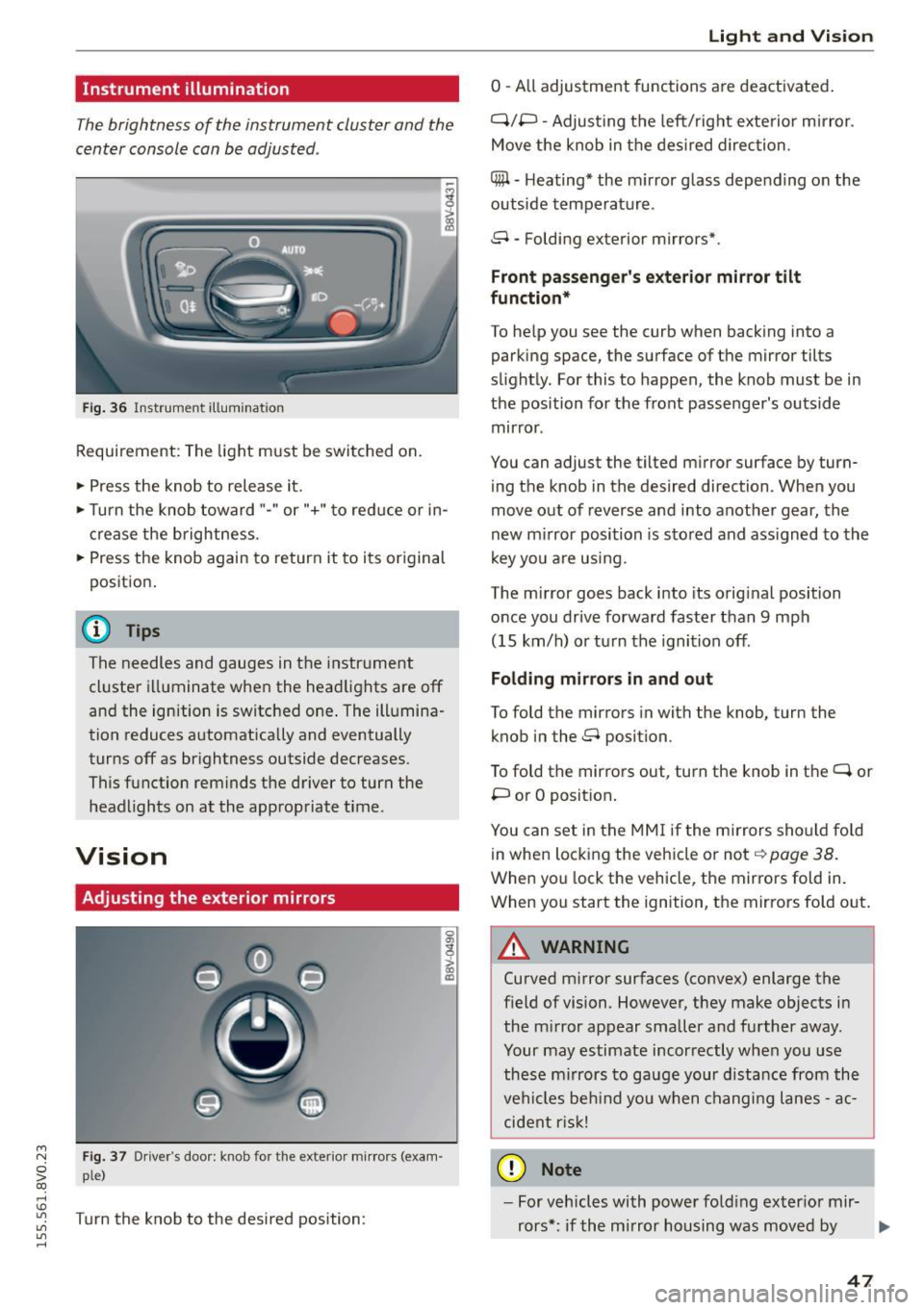
Instrument illumination
The brightness of the instrument cluster and the
center console can be adjusted .
Fig. 36 Instrument illum ination
Requirement: The light must be switched on.
.. Press the knob to release it.
.. Turn the knob toward"-" or"+" to red uce or in
crease the brightness.
.. Press the knob again to return it to its original
posit ion .
@ Tips
The needles and gauges in the instrument
cluster illuminate when the headlights are off
and the ignition is switched one . The illumina·
tion reduces automatically and eventually
turns off as br ightness outside decreases.
This function reminds the driver to turn the
headlights on at the appropriate time .
Vision
Adjusting the exterior mirrors
Fig. 37 Driver's door: knob for the exterior mirrors (exam
ple)
Turn the knob to the desired position:
0
g
> a, (X)
Light and Visio n
0 -A ll adjustment functions are deactivated .
Q/P -Adjusting the left/rig ht exterior mirror.
Move the knob in the des ired direction.
C@ · Heating* the m irror glass depending on the
outside temperature.
8 • Folding exterior mirrors*.
Front pa ss e ng er's ex te rior mirror tilt
functio n*
To help you see the curb when backing into a
parking space, the surface of the mirror tilts
slight ly. For this to happen, the knob must be in
the position for the front passenger's outside
mirror .
You can adjust the tilted mirror surface by turn·
i ng the knob in the desired direction . When you
move out of reverse and into another gear, the
new m irror position is stored and ass igned to the
key yo u are us ing .
The mirror goes back into its orig inal position
once you drive forward faster than 9 mph
(15 km/h) o r turn the ignition off.
Folding m ir rors in and out
To fold the mirrors in with the knob, turn the
knob in the 8 position.
To fold the mirrors out, turn the knob in the
q or
P or O posit ion .
You can set in the MM I if the mirrors sho uld fo ld
in when locking the vehicle or not
q page 38.
When you lock the vehicle, the mirrors fold in.
When you start the ignition, the mirrors fold out.
A WARNING -,.
Curved m irror surfaces (convex) enlarge the
field of vision. However, they make objects in
the m irror appear smaller and further away.
Your may estimate incorrectly when you use
these m irrors to gauge your d istance from the
vehi cles be hind you when changi ng lanes -ac·
cident risk!
@ Note
- For vehicles with power fo ld ing exter ior mir·
rors*: if the mirror housing was moved by
IJI,-
47
Page 59 of 282
....,
N
0 > co
rl I.O
"'
"'
"'
rl
.. To move the head restraint down, press the
button ®
<::>fig . 49 and slide the head restraint
downward.
Removing the h ead restraints
To remove the head restraints, the backrest m ust
be folded forwa rd partia lly .
.. Remove the screwdrive r from the vehicle too l
k it
9 page 241 .
.. Re lease the backrest<::> page 60 .
.. Press the but ton @ c:? fig. 49 and s lide the head
restraint up as far as it can go<::>
_A .
.. Place the screwdriver in position @ in the
opening, press the button ® and pu ll the head
restraint out of the backrest at the same time
t::>_& .
.. Fold the backrest down unt il it latches securely
t::> .A in Increasing the size of the luggage
compartment on page 60 .
Installing the head re st ra int s
To install the head restraints, the backrest must
be folded forward partially .
.. Re lease the backrest <::>
page 60 .
.. Slide the posts on the head restra int down into
the guides until you feel the posts click into
place. You should not be able to pull the head
restraint out of the backrest .
.,. Fold the backrest down unt il it latches securely
9 .A in Increasing the si ze of the luggage
compartmen t on page 60.
A WARNING
- Only remove the rear seat head restraints
w hen necessary in o rder to i nstall a chi ld
seat . Install the head restraint again imme
diately once the chi ld seat is removed. Driv
ing with the head restraints removed or
head restraints not in the highest position
increases the risk of ser ious injury .
- Read and fo llow ing the WARNINGS in
<::>
page 134.
-
Seats and storage
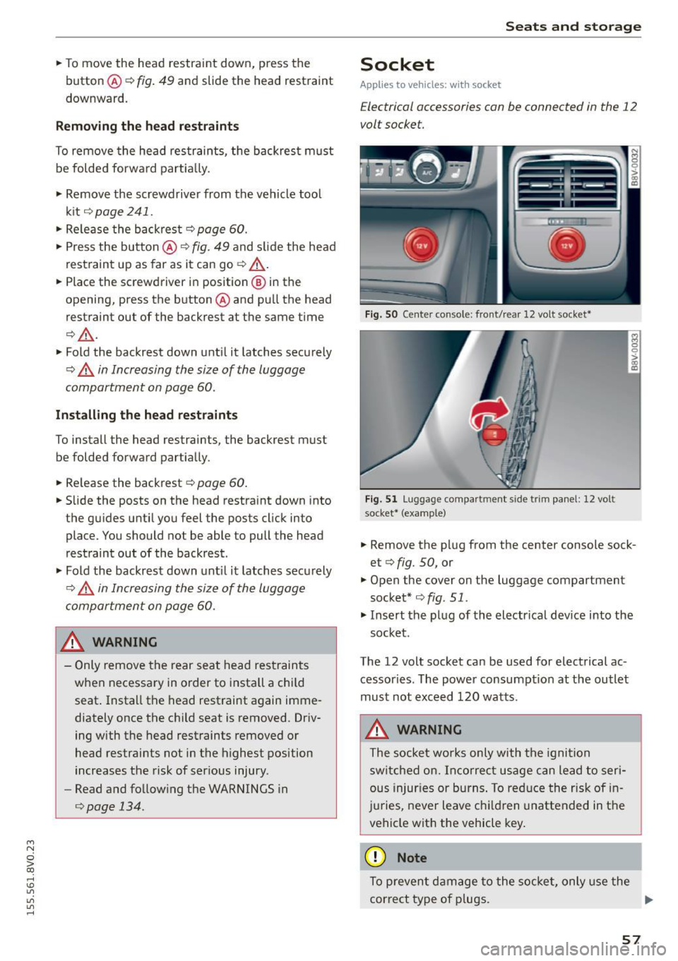
Socket
Applies to veh icles: w it h socket
Electrical accessories can be connected in the 12
volt socket.
F ig. S O Center co nsole: front/ rear 12 volt socket•
F ig. 5 1 Luggage compartm ent side trim panel: 12 volt
socket* (examp le)
.. Remove the plug from the center console sock
et <::>
fig. 50, or
.,. Open the cover on the luggage compartment
socket* <::>
fig. 51.
.,. Insert the plug of the electrical dev ice into the
socket .
The 12 volt socket can be used for electrical ac
cessories . The power consumpt ion at the outlet
must not exceed 120 watts.
A WARNING
The socket wo rks only with the igni tion
switc hed on. Inco rrect usage can lead to ser i
ous injur ies or burns . To red uce the risk of in
j u ries, never leave c hildren unattended in the
vehicle with the vehicle key .
@ Note
To prevent damage to the socket, only use the
correct type of p lugs. .,,.
57
Page 61 of 282
....,
N
0 > co
rl I.O
"'
"'
"'
rl
_& WARNING
Always leave the lid on the glove compartment cover closed while driving to reduce the
risk of injury.
Additional storage compartments
There are additional storage compartments,
compartments and holders at other locations in
the vehicle :
- In the upper part of the glove compartment.
- In the center console under the center arm-
rest* .
- On the back of the right front seat . The com
partment* can hold a maximum weight of
2 lbs
(1 kg).
- Garment hooks on the B-pillar ¢
&.
_& WARNING
-Do not place any objects on the instrument
panel. Objects that are not stored securely
can slide around in the vehicle while driving,
when accelerating or braking or when turn
ing.
- Make sure that objects cannot fall out of the
center console storage compartment or oth
er compartments and into the footwell
while driving. These objects could prevent
you from braking or accelerating during sud
den braking maneuvers.
- Garments hung on the hooks must not ob
struct the driver's view. The garment hooks
are only designed for light objects . Do not
hang any garments with hard, sharp or
heavy objects in the pockets on the garment
hooks . These objects could injure vehicle oc
cupants during sudden brak ing or in a colli
sion - especially if the airbags deploy.
- Always keep the glove compartment closed
while driving to reduce the risk of injury dur
ing a collision or heavy brak ing.
- Read and following the WARNINGS in
¢ page 168, Important safety instructions
on the side airbag system.
-Hang garments so that they do not obstruct
the driver's view.
Seats and storage
-The garment hooks should only be used for
light articles of clothing . Do not leave any
heavy or sharp-edged objects in the pockets
that could interfere with the side airbags unfolding and cause injuries in the event of
a collision .
- Do not use coat hangers to hang garments,
because this could reduce the effectiveness
of the side curtain airbags.
- Do not hang any heavy objects on the gar
ment hooks, because they could cause injury
during heavy braking.
- Because of their load capacity, the hooks
should only be used to secure objects that
weigh a max imum of 10 lb (5 kg). Heavy ob
jects will not be secured sufficiently, and
this increases the risk of injury.
luggage compartment
Loading luggage compartment
Luggage items must be stowed securely.
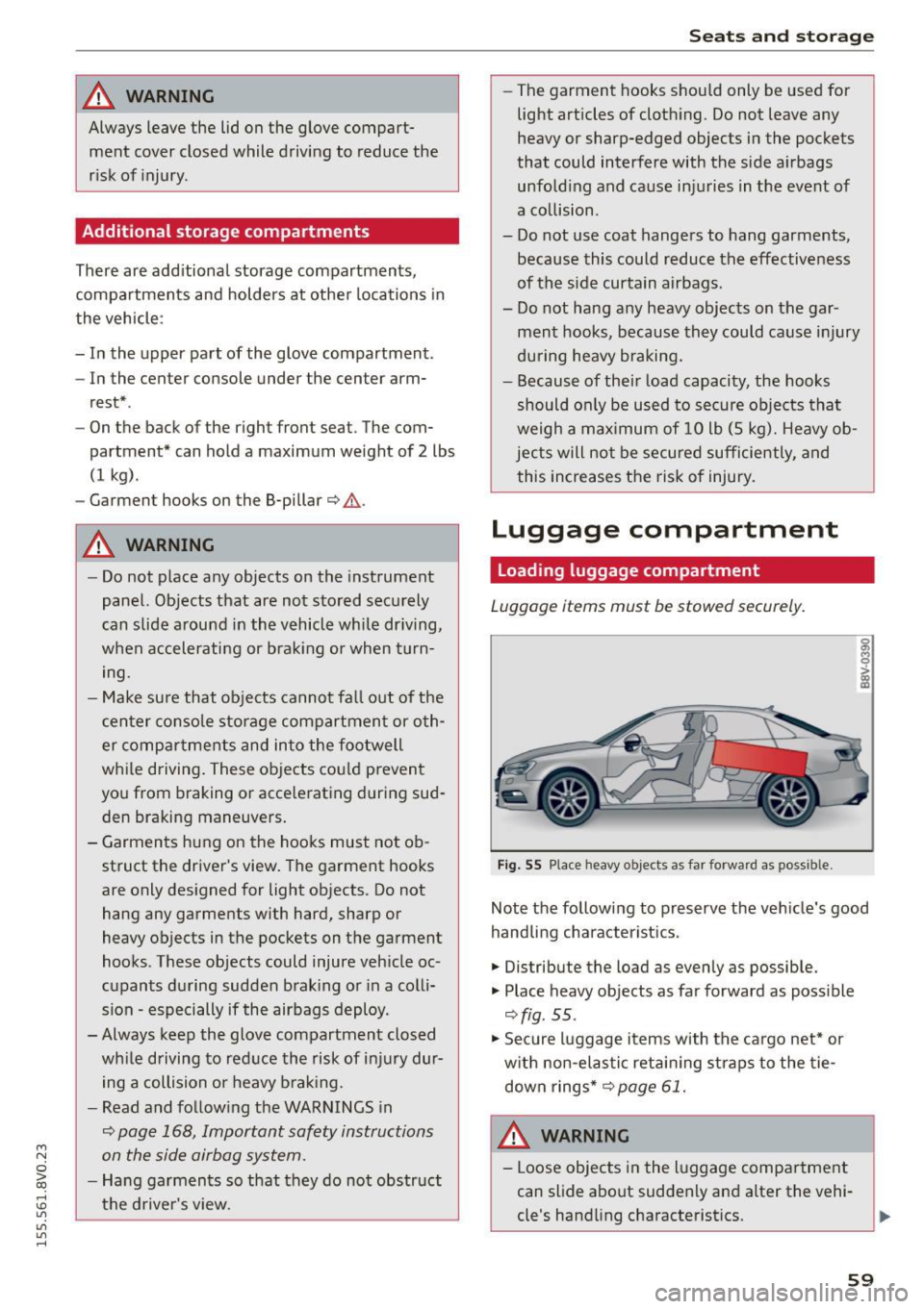
Fig. 55 Place heavy objects as far forward as poss ib le.
Note the following to preserve the vehicle's good
handling characteristics .
.,. Distribute the load as evenly as possible.
.,. Place heavy objects as far forward as possible
¢ fig . 55 .
.,. Secure luggage items with the cargo net* or
with non-elastic retaining straps to the tie
down rings* ¢
page 61.
WARNING
-Loose objects in the luggage compartment
can slide about suddenly and alter the vehi
cle's handling characteristics.
59
Page 69 of 282
shown in the disp lay. To exit "Eco" mode*, press
the
! AUTO ! button again .
I• I • I Setting the temperature
The temperature can be adjusted individually for
the dr iver and front passenger using the dials.
Tempe ratures between 60 °F ( +16 °C) and 84 ° F
(+28 °C) can be set. If outside of this range, LO or
HI will appear in the climate control system dis
p lay. In both settings, the climate contro l runs
with constantly at the maximum cooling or heat ing level. The temperature is not regulated.
Synchronization: by pressing the IAUTO I button
for two seconds, the temperature setting for the
driver is transferred to the front passenger's side.
This applies a temperature change to the front
passenger's side.
~ Adjusting the blower
To prevent the windows from fogging over, the b lower sho uld a lways ru n at a low speed. You can
ad just the volume of air generated by the b lower
to your preference. To have the blower regu lated
automatically, press the !AU TO I button .
Adjusting the air distribution
The air distribution is adjusted with the~, U!i
and ~ buttons. To have the air d istr ibut ion regu
lated automatically, press the
IAUTOI button.
The round air vents in the cockpit are adjustable
¢page 68.
To keep the windows from fogging in damp
weather, we recommend opening the side air
vents and ti lting them to the side
~ page 68,
Adjusting the air vents .
Foot vents are located under the front seats and
adjustable vents on the end o f the center console
to heat the rear of the vehicle .
~ Switching the defroster on and off
The windshield and side windows are defrosted
or cleared of condensation as quickly as possible .
The maximum amount of air flows main ly from
M
N the vents below the windshie ld. Recirculation 0
iii mode switches off . The temperat ure is contro lled
~ automatically. In the Ii] sett ing, the IA/C i cooling
Vl
Vl
......
Warm and cold
mode switches on automatically, depending on
the outside air temperat ure.
T he
IAUTO ! button switches the defroster off.
l"""I Switching recirculation mode on and off
The recircu lation mode can be turned on manual
ly or automatically* .
- Switching manual recirculation mode on and
off : press
1.,,.,1 The LED light up when switched
on .
- Automatic* recirculation mode: the auto recir
culat ion must be act ivated in the MMI. Select:
the
I MENU I button > Car > Systems* control
button
> AC > Auto recirculation . The air quali
ty sensor that is designed for diesel and gaso
line exhaust automatically switches the recircu
lation mode on or off depending on the level of
pollutants in the outside air .
In recircu lation mode, the air inside the vehicle is
c ir cula ted and filtered. This prevents the unfil
tered air outside the vehicle from entering the
vehicle interior. We recommend switching recir
cu lation mode on when driving through a tunnel
or when sitting in traffic~ &.
T he
1-1 button, !AUTO ! or the [ii bu tton switches
recirculation mode off.
T he system switches to recirculation mode when
driv ing in reverse when the engine is cold.
_&. WARNING
You should not use the recirculation mode for
an extended period sin ce no fresh air is drawn
in. With the air-conditioning switched off, the
windows can fog up, which increases the risk
of an acc ident.
67
Page 114 of 282

Assist Driver messages
Appl ies to vehicles: with Audi side assist
If the side assist switches off automatically, a
message appears in the instrument cluster dis
p la y.
@j Audi side assist: currently unavailable.
No sensor vision
The radar sensors' vision is affected. Do not cover
the area in front of the sensors with bike wheels,
stickers, dirt or other objects. Clean the area in
front of the sensors, if necessary
r:!> page 110,
fig. 98.
@j Audi side assist: currently unavailable
Side assist cannot be switched on temporarily be
cause there is a ma lfunction (for examp le, the
battery charge level may be too low).
@j Audi side assist: System fault!
The system cannot guarantee that it will detect
veh icles correctly and it is switched off. The sen
sors have been displaced or are faulty. Have the
system checked by an authorized Audi dealer or
authorized Audi Service Facility soon.
Audi drive select (drive
settings)
Introduction
Applies to vehicles: with Audi drive select
Audi drive select makes it possible to experience
different types of vehicle settings in one vehicle.
The driver can select from three
Comfort, Auto
and Dynamic modes using the ~.7l.'i button in the
center console or the MMI to switch between a
sporty and a comfortable driving mode, for ex
ample . In the
individual* mode, the settings can
be adjusted to your personal preferences . This
makes it possib le to combine settings such as a
sporty engine tun ing with light steering .
.,&. WARNING
Using Audi drive select incorrect ly can lead to
collisions, other accidents and serious inju
ries.
112
· Description
Applies to vehicles: with Audi drive se lect
The vehicle setup in each mode depends on the
vehicle's features. However , the eng ine and steer
ing are always affected.
Engine and automatic transmission
Depending on the mode, the engine and auto
matic transmission* respond more qu ickly or in a
more balanced manner to accelerator peda l
movements .
Adaptive dampers (Audi magnetic ride)*
The adaptive dampers use sensors to record in
format ion regarding steer ing movements, brak
ing and acce lerat ion operations by the driver,
road surface, dr iv ing speed, and load. With Audi
drive select you can adjust the adaptive dampers
sporty (dynamic), comfortable (comfort) or bal
anced (auto).
Steering
T he steer ing adapts in terms of steer ing ass is
tance. There a re diffe rent modes
Q page 113.
Indirect steering that moves easily as in comfort
mode is especia lly suited to long drives on a high
way. The dynamic mode provides sporty, direct
steering .
For vehicles with progressive steering* the steer
ing performance is more agi le .
Cornering light*
The cornering light adjusts when driv ing on
curves at speeds between 6 mph (10 km/h) and
68 mph (110 km/h). The pivoting action and the
lig hting are also adapted to the mode.
Adaptive cruise control*
The behavior when accelerating can be adjusted
from comfortable to sporty, depending on the
Audi drive select mode. Adaptive cruise control
also responds to the driving behavior of the vehi
cle ahead in a more conservative or sporty man
ner.
Page 115 of 282
....,
N
0 > co
rl I.O
"'
"'
"'
rl
@ Tips
In some models, the maximum vehicle speed
can only be reached in the auto and dynamic
modes.
Selecting the driving mode
A ppl ies to vehicles: with Audi drive select
You con choose between comfort, auto, dynamic
and individual* .
Fig. 99 Center console: dr ive selec t button
Fig . 100 MMI : drive select
Adjusting the Individual mode Assist
.,.
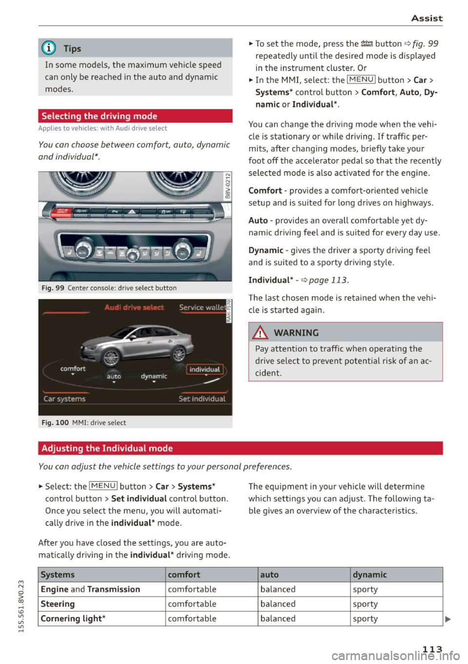
To set the mode, press the r:1:.~ button ~ fig. 99
repeatedly until the desired mode is displayed
in the instrument cluster. Or
.,. In the MMI, select: the
I MENU I button >C ar>
Systems"
control button > Comfort, Auto, Dy
namic or Individual ".
You can change the driving mode when the vehi
cle is stationary or while driving.
If traffic per
mits, after changing modes, briefly take your
foot off the accelerator pedal so that the recently
selected mode is also activated for the engine .
Comfort -provides a comfort-oriented vehicle
setup and is suited for long drives o n highways.
Auto -provides an overall comfortable yet dy
namic driving feel and is suited for every day use.
Dynamic -gives the driver a sporty driving feel
and is suited to a sporty driving sty le.
Individual* -<=>page 113.
The last chosen mode is retained when the veh i
cle is started again .
.&, WARNING
-Pay attention to traffic when operating the
drive select to prevent potential risk of an ac
cident.
You con adjust the vehicle settings to your personal preferences .
.,. Select : the IMENU ! button> Car> Systems*
control button > Set individual control button .
Once you select the menu, you will automat i
ca lly dr ive in the
individual* mode .
After you have closed the settings, you are auto mat ically dr iving in the
individual * driving mode .
Systems comfort
Engine
and Transmission comfortable
Steering comfortable
Cornering light* comfortable The equipment
in your vehicle will determine
which sett ings you can adjust. The following ta
ble g ives an overview of the characteristics .
auto dynamic
balanced sporty
balanced sporty
ba lanced sporty
113
Page 119 of 282
....,
N
0 > co
rl I.O
"'
"'
"'
rl
Switching on/off
Applies to vehicles: with parking system plus
F ig. 102 Ce nter console: parking a id button
Fig. 103 MMI: opt ical d istance d isplay
Switching on
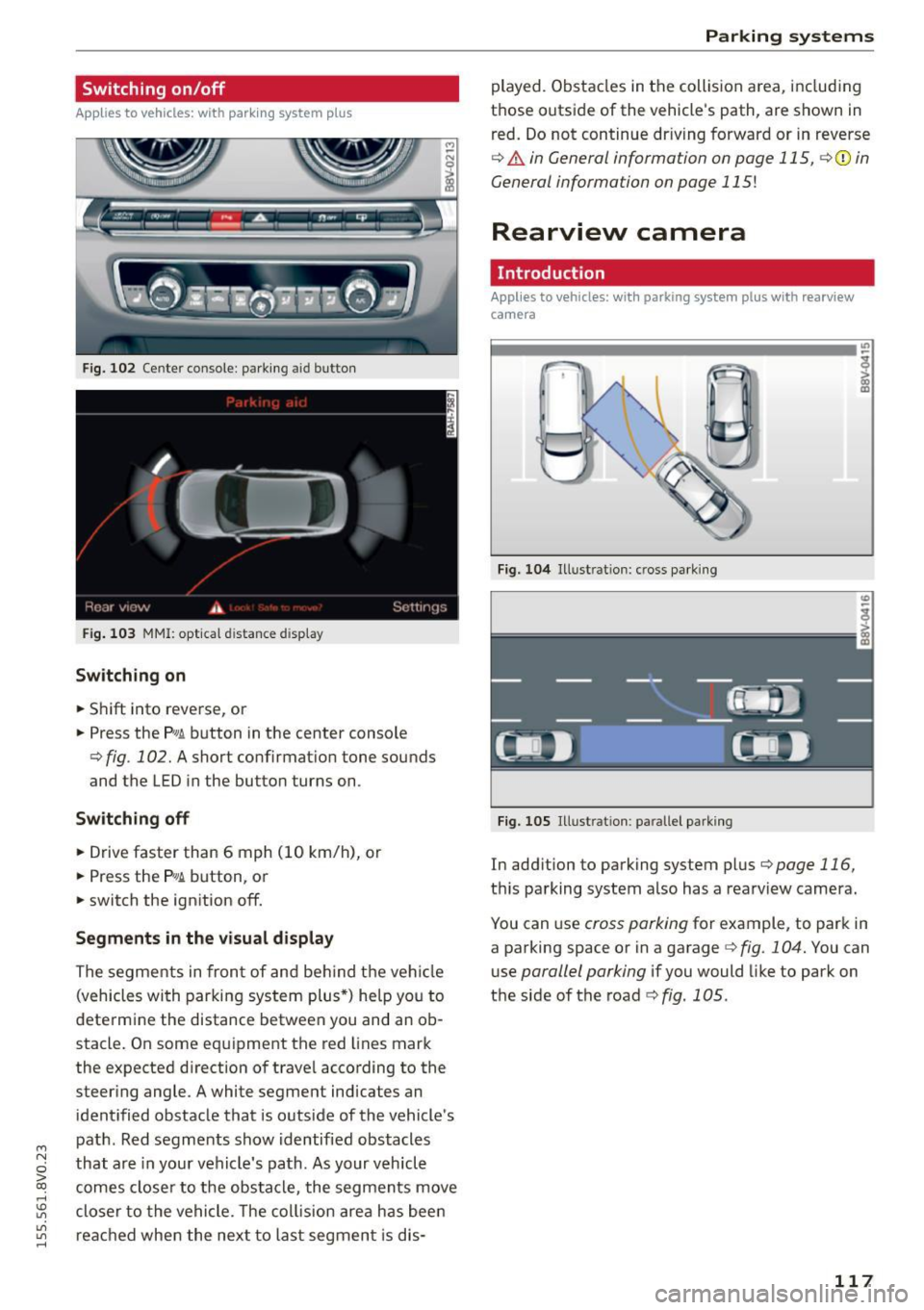
• Shift into reverse, or
• Press the
p,g ~ button in the center console
¢ fig . 102. A short confirmat ion tone sounds
and the LED in the butto n turns on .
Switching off
• Drive faster than 6 mph (10 km/h), or
• Press the
P,g~ button, or
• switch the ignition off.
Segments in the visual display
The segments in fron t of and behind the vehicle
(vehicles with parking system plus*) he lp you to
determine the distance between you and an ob
stacle. On some equipment the red lines mark
the expected d irection of trave l according to the
steer ing angle . A white segment indicates an
identified obstacle that is outside of the vehicle's
path . Red segments show identified obstacles
that are in your vehicle's path. As your vehicle
comes closer to the obstacle, the segments move
closer to the vehicle. The collision area has been
reached when the next to last segmen t is dis-
Parking systems
played. Obstacles in the collision a rea, including
those outside of the veh icle's path, are shown in
red. Do not continue dr iving forward or in reverse
¢ & in General information on page 115, ¢(i) in
General information on page 115!
Rearview camera
Introduction
Applies to vehicles: wit h parking sys tem plus with rearview
camera
Fig. 104 Illust rat ion : cross parking
Fig. 105 Illust ration : pa ralle l park ing
In add ition to parking system plus ¢page 116,
this parking system also has a rearv iew camera.
You can use
cross parking for example, to park in
a parking space or in a garage
¢ fig . 104. You can
use
parallel parking if you would like to park on
the side of the road
¢ fig. 1 OS.
117
Page 121 of 282
....,
N
0 > co
rl I.O
"'
"'
"'
rl
Switching on/off
Applies to vehicles: with parking system plus w it h rearv iew
camera
Switching on
• Shift into reverse, or
• Press the
P~A button in the center console
¢page 117, fig. 102. A short confirmation
tone sounds and the LED in the button turns
on.
Switching between the rearview camera and
optical display
• Press the Graphic control button ®
r::!.>page 119, fig . 108 to see the optica l display.
• Press the
Rear view contro l button to see the
rearview camera image.
Switching off
• Drive faster than 6 mph (10 km/h), or
• Press the
P,qA button, or
• switch the ign ition off.
@ Tips
The v isual display in the left pa rt of the dis
play should he lp you detect the critical veh icle
areas.
Cross parking
Appl ies to vehicles : with parking system plus with rearview
camera
This view may be used when parking in a garage
or in a parking space.
Fi g. 108 MMI: aiming at a park ing spot
Parking systems
Gr,11;t I( i._ S,·T .. 1',lJ',
Fig. 109 MMI : aligning t he veh icle
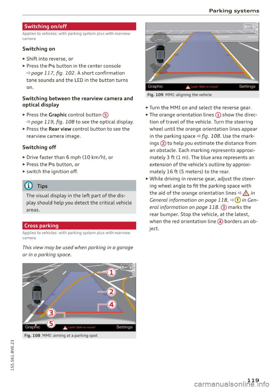
• Turn the MM I on and select the reverse gear .
• The orange orientation lines
(D show the direc
tion of travel of the vehicle . Turn the steering
wheel unt il the orange orientation lines appear
in the parking space¢
fig. 108. Use the mark
in gs @ to help you estimate the distance from
an obstacle . Each marking represents approxi
mately 3 ft (1 m) . The blue area represents an
extens ion of the vehicle 's outline by approxi
mate ly 16 ft (5 meters) to the rear.
• Wh ile driving in reverse gear, adjust the steer
ing wheel angle to fit the park ing space with
the aid of the orange or ientat ion lines
Q A in
General information on page 118,
r::!.>0 in Gen
eral information on page 118.@
marks the
rea r bumper . S top the vehicle, at the latest,
when the red orienta tion line © borders an ob
ject.
119