Page 31 of 356
SPECIAL TOOLS
1-17
Pocket tester
90890-03112
Analog pocket tester
YU-03112-CThis tool is used to measure
the voltage, current, and re-
sistance of electrical compo-
nents.
Timing light
90890-03141
YU-03141This tool is used to measure
the ignition timing.
Pressure gauge
90890-03153
YU-03153This tool is used to measure
the fuel pressure.
Yamaha diagnostic tool
90890-03215This tool is used to check er-
ror codes or carry out self-di-
agnosis.
Fuel pressure adapter
90890-03186
YM-03186This tool is used to mount the
pressure gauge.
Test harness S-pressure
sensor (3P)
90890-03207
YU-03207This tool is used to check the
throttle position sensor input
voltage.
FI diagnostic tool sub-lead
90890-03212
YU-03212This tool is used to connect
the Yamaha diagnostic tool
to a battery.
Spacer (crankshaft installer)
90890-04081
Pot spacer
YM-91044This tool is used to install the
crankshaft. Tool name/Part number How to use Illustration
YM-91044
Page 299 of 356

FUEL INJECTION SYSTEM
8-13
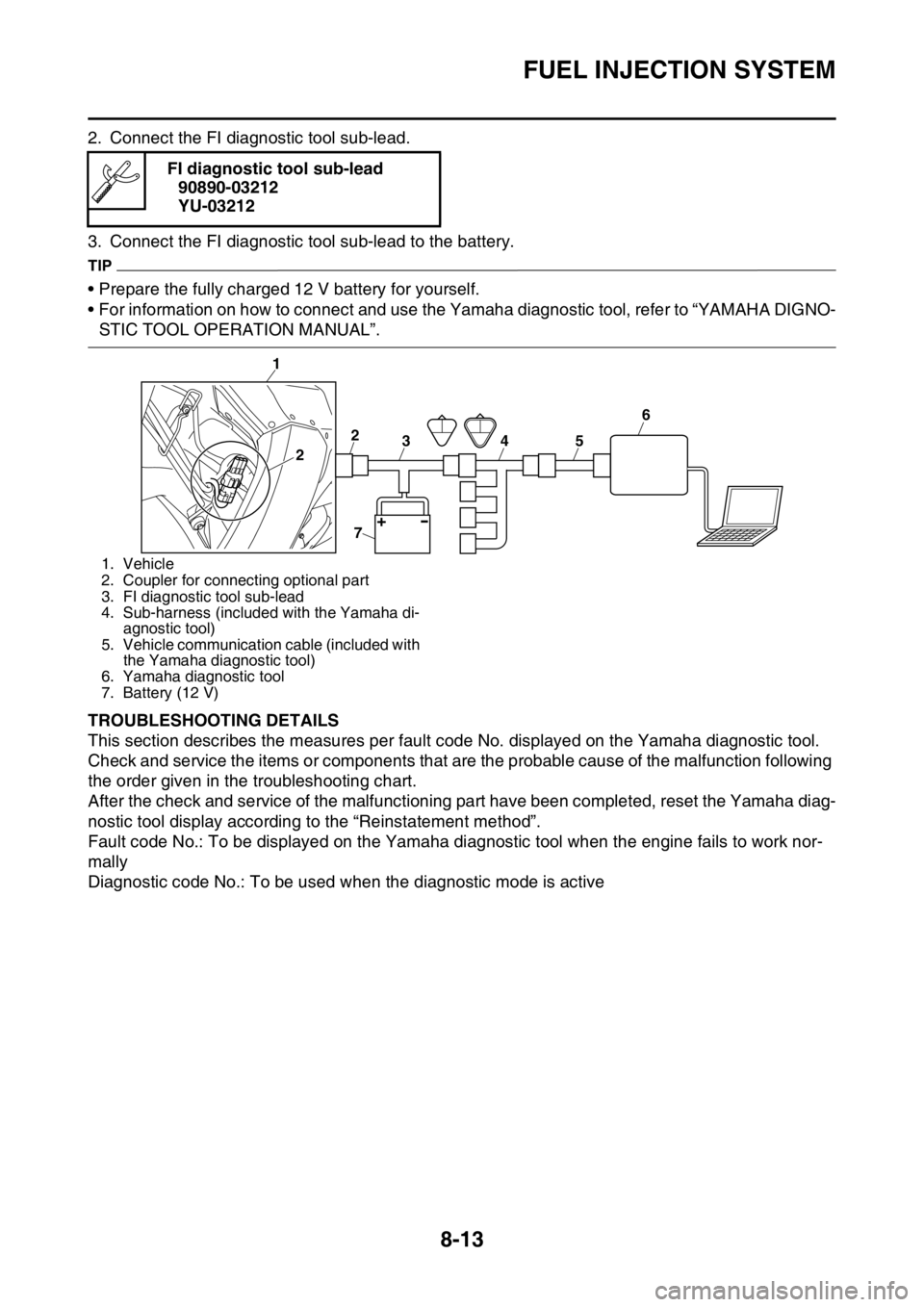
2. Connect the FI diagnostic tool sub-lead.
3. Connect the FI diagnostic tool sub-lead to the battery.
TIP
• Prepare the fully charged 12 V battery for yourself.
• For information on how to connect and use the Yamaha diagnostic tool, refer to “YAMAHA DIGNO-
STIC TOOL OPERATION MANUAL”.
EAS1SM1329TROUBLESHOOTING DETAILS
This section describes the measures per fault code No. displayed on the Yamaha diagnostic tool.
Check and service the items or components that are the probable cause of the malfunction following
the order given in the troubleshooting chart.
After the check and service of the malfunctioning part have been completed, reset the Yamaha diag-
nostic tool display according to the “Reinstatement method”.
Fault code No.: To be displayed on the Yamaha diagnostic tool when the engine fails to work nor-
mally
Diagnostic code No.: To be used when the diagnostic mode is active FI diagnostic tool sub-lead
90890-03212
YU-03212
1. Vehicle
2. Coupler for connecting optional part
3. FI diagnostic tool sub-lead
4. Sub-harness (included with the Yamaha di-
agnostic tool)
5. Vehicle communication cable (included with
the Yamaha diagnostic tool)
6. Yamaha diagnostic tool
7. Battery (12 V)
1
3 2
2456
7
Page 340 of 356

LIST OF SELF-DIAGNOSTIC AND FAIL-SAFE ACTIONS
9-5
SENSOR OPERATION TABLE
Diag-
nostic
code
No.ITEM Display Procedure
01 Throttle angle
• Fully closed position
• Fully opened positionDisplays the throttle angle.
• 11–14
• 109–116• Check with throttle fully
closed.
• Check with throttle fully
opened.
03 Pressure of suction pipe Displays the intake air pres-
sure.The atmospheric pressure
is displayed on the Yamaha
diagnostic tool.
05 Intake air temperature Displays the intake air tem-
perature.Compare the actually mea-
sured intake air tempera-
ture with the Yamaha
diagnostic tool display val-
ue.
06 Coolant temperature Displays the coolant temper-
ature.Compare the actually mea-
sured coolant temperature
with the Yamaha diagnostic
tool display value.
08 Lean angle sensor
• Upright
•OverturnDisplays the output voltage.
• 1.0 (V)
• 4.0 (V)Remove the ECU, and in-
cline it 45 ° or more.
09 Monitor voltage Displays the voltage of the
external battery connected to
the Yamaha diagnostic tool.
• Approximately 12.0 (V)—
21 Neutral switch
• Gear in neutral
• Gear not in neutral•ON
•OFFOperate the shift pedal.
25 Gear position sensor
• Gear in 1st or 2nd
• Gear not in 1st or 2nd•ON
•OFFOperate the shift pedal.
60 EEPROM fault code No.
display
• No fault
• CO adjustment valve
• Power Tuner injection cor-
rection setting 0–8, or
Power Tuner ignition tim-
ing correction setting 0–8•00
•01
•07—
61 Malfunction history ( )
code No. display
*1
• There is no history.
• There is some history.•00
• Other: Displays the fault
code of ( ).—