Page 24 of 84

INSTRUMENT AND CONTROL FUNCTIONS
3-8
3
EAU1234H
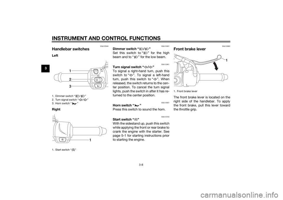
Handle bar switchesLeft
Ri ght
EAU12401
Dimmer switch “ / ”
Set this switch to “ ” for the high
beam and to “ ” for the low beam.
EAU12461
Turn si gnal switch “ / ”
To signal a right-hand turn, push this
switch to “ ”. To signal a left-hand
turn, push this switch to “ ”. When
released, the switch returns to the cen-
ter position. To cancel the turn signal
lights, push the switch in after it has re-
turned to the center position.
EAU12501
Horn switch “ ”
Press this switch to sound the horn.
EAU12722
Start switch “ ”
With the sidestand up, push this switch
while applying the front or rear brake to
crank the engine with the starter. See
page 5-1 for starting instructions prior
to starting the engine.
EAU12902
Front brake leverThe front brake lever is located on the
right side of the handlebar. To apply
the front brake, pull this lever toward
the throttle grip.
1. Dimmer switch “ / ”
2. Turn signal switch “ / ”
3. Horn switch “ ”
1. Start switch “ ”
123
1
1. Front brake lever
1
U2CME0E0.book Page 8 Friday, May 2, 2014 2:55 PM
Page 25 of 84

INSTRUMENT AND CONTROL FUNCTIONS
3-9
3
EAUS1963
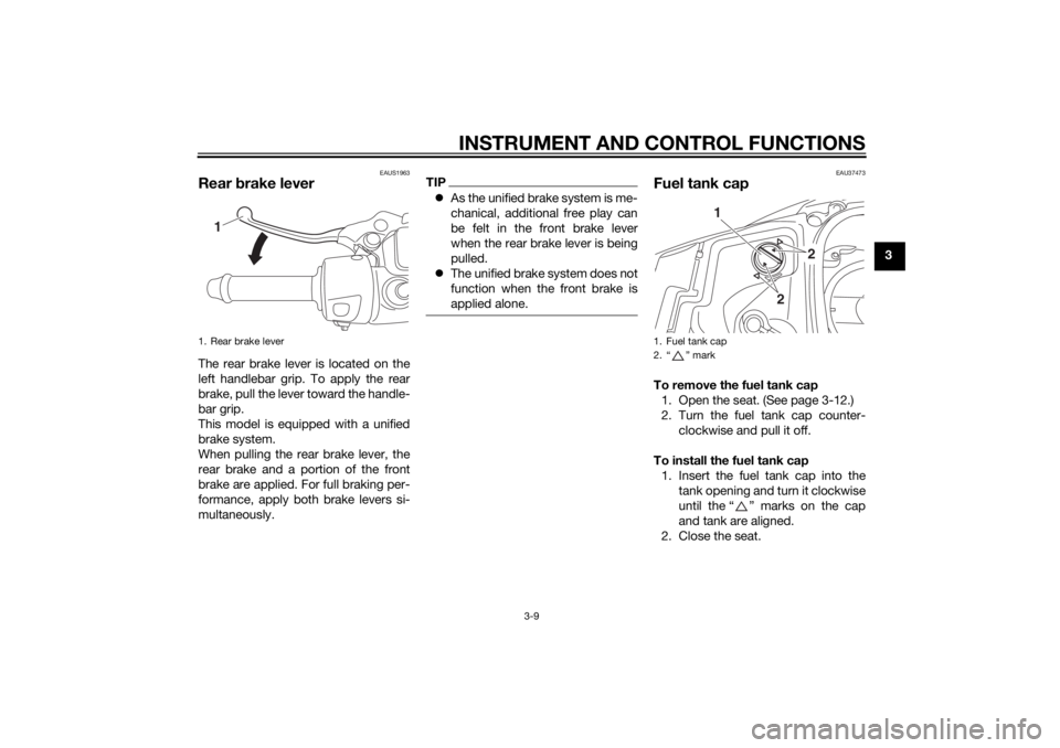
Rear brake leverThe rear brake lever is located on the
left handlebar grip. To apply the rear
brake, pull the lever toward the handle-
bar grip.
This model is equipped with a unified
brake system.
When pulling the rear brake lever, the
rear brake and a portion of the front
brake are applied. For full braking per-
formance, apply both brake levers si-
multaneously.
TIP As the unified brake system is me-
chanical, additional free play can
be felt in the front brake lever
when the rear brake lever is being
pulled.
The unified brake system does not
function when the front brake is
applied alone.
EAU37473
Fuel tank capTo remove the fuel tank cap
1. Open the seat. (See page 3-12.)
2. Turn the fuel tank cap counter- clockwise and pull it off.
To install the fuel tank cap 1. Insert the fuel tank cap into the tank opening and turn it clockwise
until the “ ” marks on the cap
and tank are aligned.
2. Close the seat.
1. Rear brake lever
1
1. Fuel tank cap
2. “ ” mark
2
2
1
U2CME0E0.book Page 9 Friday, May 2, 2014 2:55 PM
Page 72 of 84

PERIODIC MAINTENANCE AND ADJUSTMENT
6-33
6En
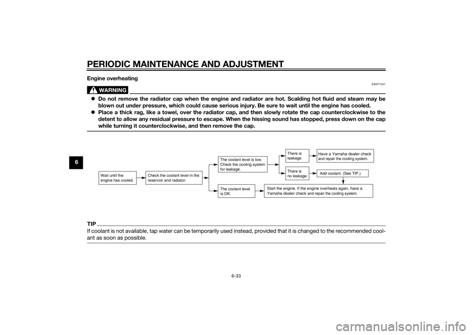
gine overheatin g
WARNING
EWAT1041
Do not remove the ra diator cap when the en gine an d ra diator are hot. Scal din g hot flui d an d steam may be
b lown out un der pressure, which coul d cause serious injury. Be sure to wait until the en gine has coole d.
Place a thick ra g, like a towel, over the ra diator cap, an d then slowly rotate the cap counterclockwise to the
d etent to allow any resi dual pressure to escape. When the hissin g soun d has stoppe d, press d own on the cap
while turnin g it counterclockwise, an d then remove the cap.TIPIf coolant is not available, tap water can be temporarily used instead, provided that it is changed to the recommended cool-
ant as soon as possible.
Wait until the
engine has cooled.
Check the coolant level in the
reservoir and radiator.
The coolant level
is OK.The coolant level is low.
Check the cooling system
for leakage.
Have a Yamaha dealer checkand repair the cooling system.Add coolant. (See TIP.)
Start the engine. If the engine overheats again,
have a
Yamaha dealer check
and repair the cooling system.
There is
leakage.
There is
no leakage.
U2CME0E0.book Page 33 Friday, May 2, 2014 2:55 PM