2014 YAMAHA TRICITY key
[x] Cancel search: keyPage 32 of 84

INSTRUMENT AND CONTROL FUNCTIONS
3-16
3
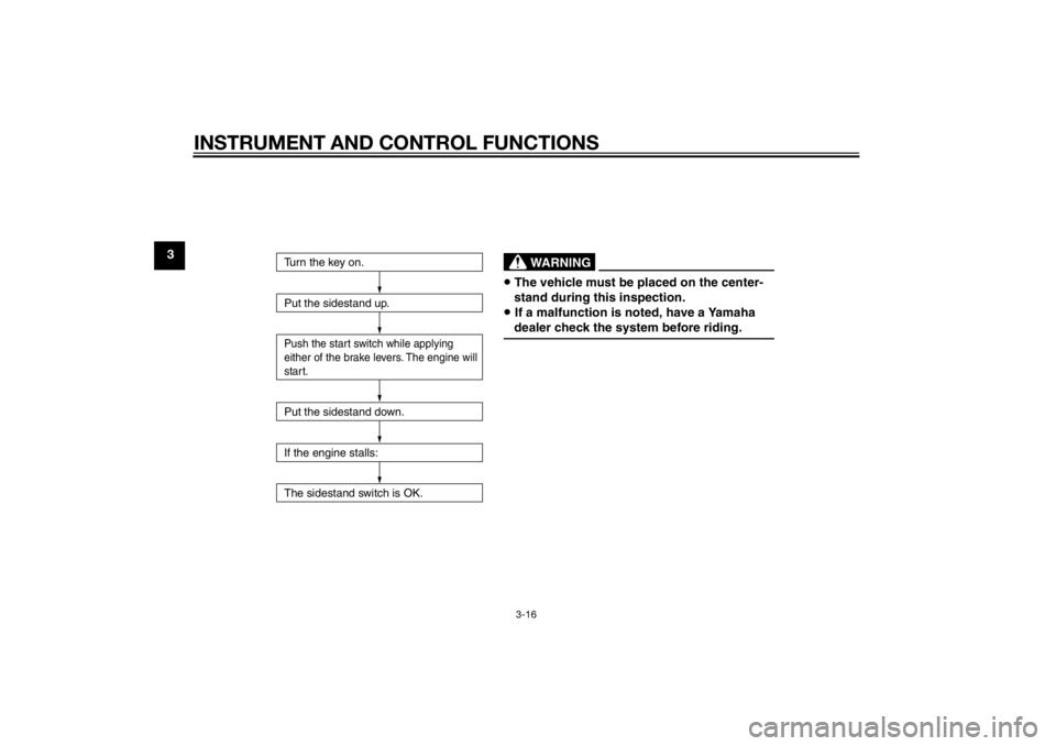
Turn the key on.
Put the sidestand up.Push the start switch while applying
either of the brake levers. The engine will
start.Put the sidestand down.
If the engine stalls:
The sidestand switch is OK.
• The vehicle must be placed on the center-
stand during this inspection.• If a malfunction is noted, have a Yamaha
dealer check the system before riding.
WARNING
U2CME0E0.book Page 16 Friday, May 2, 2014 2:55 PM
Page 33 of 84

INSTRUMENT AND CONTROL FUNCTIONS
3-17
3
EAU61140
Auxiliary DC connectorNOTICE
ECA21160
The accessory connected to the
auxiliary DC connector shoul d not
b e used with the en gine turne d off,
an d the loa d must never excee d 120
W (10 A), otherwise the fuse may
b low or the battery may d ischarge.This vehicle is equipped with an auxil-
iary DC connector. A 12–V accessory
connected to the auxiliary DC connec-
tor can be used when the key is in the
“ON” position.1. Auxiliary DC connector
1
U2CME0E0.book Page 17 Friday, May 2, 2014 2:55 PM
Page 36 of 84

OPERATION AND IMPORTANT RIDING POINTS
5-1
5
EAU15952
Read the Owner’s Manual carefully to
become familiar with all controls. If
there is a control or function you do not
understand, ask your Yamaha dealer.
WARNING
EWA10272
Failure to familiarize yourself with
the controls can lead to loss of con-
trol, which coul d cause an acci dent
or injury.
EAU45311
TIPThis model is equipped with a lean an-
gle sensor to stop the engine in case of
a turnover. To start the engine after a
turnover, be sure to turn the main
switch to “OFF” and then to “ON”. Fail-
ing to do so will prevent the engine
from starting even though the engine
will crank when pushing the start
switch.
EAU60631
Startin g the en gineNOTICE
ECA10251
See pag e 5-3 for en gine break-in in-
structions prior to operatin g the ve-
hicle for the first time.In order for the ignition circuit cut-off
system to enable starting, the side-
stand must be up. See page 3-15 for more information. 1. Turn the key to “ON”. The following warning lights
should come on for a few sec-
onds, then go off. Engine trouble warning light
Coolant temperature warning
lightNOTICE
ECA15485
If a warnin g li ght does not come on
initially when the key is turned to
“ON”, or if a warnin g li ght remains
on, see pa ge 3-2 for the correspon d-
in g warnin g li ght circuit check.2. Close the throttle completely.
U2CME0E0.book Page 1 Friday, May 2, 2014 2:55 PM
Page 39 of 84

OPERATION AND IMPORTANT RIDING POINTS
5-4
5
150–500 km (90–300 mi)
Avoid prolonged operation above 1/2
throttle.
Rev the engine freely through the
gears, but do not use full throttle at any
time.
500–1000 km (300–600 mi)
Avoid prolonged operation above 3/4
throttle.
1000 km (600 mi) an
d b eyon d
Avoid prolonged full-throttle operation.
Vary the engine speed occasionally.
NOTICE: After 1000 km (600 mi) of
operation, be sure to chan ge the en-
g ine oil an d final transmission oil,
an d to clean the oil strainer.
[ECA16502]
NOTICE
ECA10271
If any en gine trou ble shoul d occur
d urin g the en gine break-in perio d,
imme diately have a Yamaha dealer
check the vehicle.
EAU17214
Parkin gWhen parking, stop the engine, and
then remove the key from the main
switch.
WARNING
EWA10312
Since the en gine an d exhaust
system can b ecome very hot,
park in a place where ped estri-
ans or chil dren are not likely to
touch them an d b e burne d.
Do not park on a slope or on soft
groun d, otherwise the vehicle
may overturn, increasin g the
risk of a fuel leak an d fire.
Do not park near grass or other
flamma ble materials which
mi ght catch fire.
U2CME0E0.book Page 4 Friday, May 2, 2014 2:55 PM
Page 66 of 84

PERIODIC MAINTENANCE AND ADJUSTMENT
6-27
6battery tends to discharge more quick-
ly if the vehicle is equipped with op-
tional electrical accessories.
NOTICE
ECA16522
To char
ge a VRLA (Valve Re gulate d
Lea d Aci d) battery, a special (con-
stant-volta ge) battery char ger is re-
quire d. Usin g a conventional battery
char ger will damag e the b attery.To store the b attery
1. If the vehicle will not be used for more than one month, remove the
battery, fully charge it, and then
place it in a cool, dry place.
NOTICE: When removin g the
b attery, be sure the key is
turne d to “OFF”, then discon-
nect the neg ative lead b efore
d isconnectin g the positive lea d.
[ECA16303]
2. If the battery will be stored for
more than two months, check it at
least once a month and fully
charge it if necessary.
3. Fully charge the battery before in- stallation. NOTICE: When install-
in g the b attery, be sure the key is turne
d to “OFF”, then connect
the positive lea d before con-
nectin g the ne gative lea d.
[ECA16841]
4. After installation, make sure that
the battery leads are properly con-
nected to the battery terminals.NOTICE
ECA16531
Always keep the b attery charged .
Storin g a d ischar ged battery can
cause permanent battery damag e.
EAU60981
Replacin g the fusesThe main fuse and the fuse box, which
contains the fuses for the individual cir-
cuits, are located under the seat. (See
page 3-12.)1. Fuse box
2. Spare main fuse
3. Main fuse
1
2
3
U2CME0E0.book Page 27 Friday, May 2, 2014 2:55 PM
Page 67 of 84

PERIODIC MAINTENANCE AND ADJUSTMENT
6-28
6
If a fuse is blown, replace it as follows. 1. Turn the key to “OFF” and turn off the electrical circuit in question.
2. Open the seat. (See page 3-12.)
3. Remove the fuse box cover as shown. 4. Remove the blown fuse, and then
install a new fuse of the specified
amperage. WARNING! Do not
use a fuse of a hi gher ampera ge
ratin g than recommen ded to
avoi d causin g extensive dam-
a g e to the electrical system an d
possi bly a fire.
[EWA15132]
5. Turn the key to “ON” and turn on
the electrical circuit in question to
check if the device operates.
6. If the fuse immediately blows again, have a Yamaha dealer
check the electrical system.
7. Install the fuse box cover, and then close the seat.
1. Backup fuse (for clock)
2. Signaling system fuse
3. Headlight fuse
4. Spare fuse
123
4
1. Fuse box cover
Specified fuses:
Main fuse: 20.0 A
Headlight fuse: 15.0 A
Signaling system fuse:
10.0 A
Backup fuse: 10.0 A
1
U2CME0E0.book Page 28 Friday, May 2, 2014 2:55 PM
Page 82 of 84

10-1
10
INDEXAAcceleration and deceleration ................ 5-2
Air filter and V-belt case air filter elements ............................................. 6-14
Auxiliary DC connector ......................... 3-17
Auxiliary light......................................... 6-30BBattery .................................................. 6-26
Brake fluid, changing ............................ 6-22
Brake fluid level, checking .................... 6-20
Brake lever, front .................................... 3-8
Brake lever, rear...................................... 3-9
Brake levers, lubricating ....................... 6-23
Braking.................................................... 5-3CCables, checking and lubricating ......... 6-22
Care ........................................................ 7-1
Catalytic converter ................................ 3-11
Centerstand and sidestand, checking and lubricating .................................... 6-23
Coolant ................................................. 6-13
Coolant temperature warning light ......... 3-3DDimmer switch ........................................ 3-8EEngine break-in....................................... 5-3
Engine oil and oil strainer...................... 6-10
Engine serial number .............................. 9-1
Engine trouble warning light ................... 3-3FFinal transmission oil ............................ 6-12
Front and rear brake pads, checking.... 6-20
Front brake lever free play, checking ... 6-19
Front fork, checking .............................. 6-24 Fuel ....................................................... 3-10
Fuel consumption, tips for reducing ...... 5-3
Fuel tank cap .......................................... 3-9
Fuses, replacing ................................... 6-27
HHandlebar switches ................................ 3-8
Headlight bulb, replacing ..................... 6-29
High beam indicator light ....................... 3-2
Horn switch ............................................ 3-8IIdentification numbers ............................ 9-1
Ignition circuit cut-off system ............... 3-15
Indicator lights and warning lights ......... 3-2KKeyhole shutter ...................................... 3-2LLeaning system, checking .................... 6-26
Luggage hook ...................................... 3-14MMain switch/steering lock....................... 3-1
Maintenance and lubrication, periodic ... 6-4
Maintenance, emission control
system.................................................. 6-3
Matte color, caution ............................... 7-1
Model label ............................................. 9-1
Multi-function meter unit ........................ 3-4PPanel, removing and installing ............... 6-8
Parking ................................................... 5-4
Part locations ......................................... 2-1
Passenger footrest ............................... 3-13RRear brake lever free play, checking .... 6-19
SSafe-riding points....................................1-5
Safety information ...................................1-1
Seat .......................................................3-12
Self-diagnosis device..............................3-3
Sidestand ..............................................3-14
Spark plug, checking ..............................6-8
Specifications .........................................8-1
Starting off ..............................................5-2
Starting the engine ..................................5-1
Start switch .............................................3-8
Steering, checking ................................6-25
Steering tie rod, checking .....................6-25
Storage ...................................................7-4
Storage compartment ...........................3-13TTail/brake light ......................................6-30
Throttle grip and cable, checking and
lubricating ...........................................6-22
Throttle grip free play, checking ...........6-16
Tires ......................................................6-17
Tool kit ....................................................6-2
Troubleshooting ....................................6-31
Troubleshooting charts .........................6-32
Turn signal indicator lights ......................3-2
Turn signal light bulb.............................6-30
Turn signal switch ...................................3-8VValve clearance .....................................6-16
Vehicle identification number ..................9-1WWheel bearings, checking .....................6-25
Wheels ..................................................6-18
U2CME0E0.book Page 1 Friday, May 2, 2014 2:55 PM