Page 25 of 100

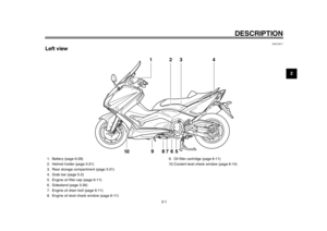
INSTRUMENT AND CONTROL FUNCTIONS
3-10
234
5
6
7
8
9
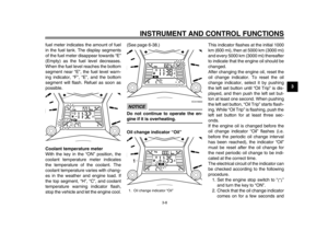
ture display “Air”, the average fuel con-
sumption mode “AVE_ _._ MPG” and
the instantaneous fuel consumption
mode “MPG” in the following order:
Air
AVE_ _._ MPG MPG Air
Ambient temperature display
This display shows the ambient tem-
perature from –9 C to 40 C in 1 C in-
crements.
For the UK only:
15 F to 104 F in 1 F increments.
The temperature displayed may vary from the ambient temperature. Pushing
the right set button switches the ambi-
ent temperature display to the average
fuel consumption and instantaneous
fuel consumption modes.
Average fuel consumption mode
The average fuel consumption display
can be set to either “AVE_ _._ km/L” or
“AVE_ _._ L/100 km” (except for the
UK).
For the UK only:
The average fuel consumption is dis-
played “AVE_ _._ MPG”.
This display shows the average fuelconsumption since it was last reset.
When the display is set to “AVE_
_._ km/L”, the average distance
that can be traveled on 1.0 L of fuel
is shown.
When the display is set to “AVE_
_._ L/100 km”, the average
amount of fuel necessary to travel
100 km is shown.
For the UK only: When the display
is set to “AVE_ _._ MPG”, the av-
erage distance that can be trav-
eled on 1.0 Imp.gal of fuel is
shown.
To reset the average fuel consumption
display, select it by pushing the right set
button, and then push the right set but-
ton for at least one second.
TIPAfter resetting an average fuel con-
sumption display, “_ _._” is shown for
that display until the vehicle has trav-eled 1 km (0.6 mi).
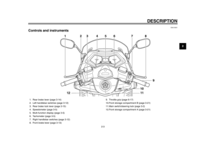
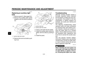
1. Ambient temperature display1
1. Average fuel consumption display
1
59C-9-E2.book 10 ページ 2013年6月18日 火曜日 午後1時33分
Page 26 of 100

INSTRUMENT AND CONTROL FUNCTIONS
3-11
1
23
4
5
6
7
8
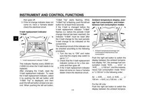
9Instantaneous fuel consumption mode
The instantaneous fuel consumption
display can be set to either “km/L” or “L/
100 km” (except for the UK).
For the UK only:
The instantaneous fuel consumption is
displayed “MPG”.
When the display is set to “km/L”,
the distance that can be traveled
on 1.0 L of fuel under the current
riding conditions is shown.
When the display is set to “L/100
km”, the amount of fuel necessary
to travel 100 km under the current
riding conditions is shown.
For the UK only: The distance that
can be traveled on 1.0 Imp.gal of
fuel under the current riding condi-
tions is shown.
To switch between the instantaneous
fuel consumption displays, push the
right set button for one second when
one of the displays is shown (except for
the UK).
TIPIf traveling at speeds under 10 km/h(6.0 mi/h), “_ _._” is displayed.
Self-diagnosis device
This model is equipped with a self-diag-
nosis device for various electrical cir-
cuits. If a problem is detected in any of those
circuits, the engine trouble warning light
comes on and the display indicates an
error code.
If the display indicates any error codes,
note the code number, and then have a
Yamaha dealer check the vehicle.
The self-diagnosis device also detects
problems in the immobilizer system cir-
cuits.
If a problem is detected in any of the im-
mobilizer system circuits, the immobi-
lizer system indicator light flashes and
the display indicates an error code.
TIPIf the display indicates error code 52,
this could be caused by transponder in-
terference. If this error code appears,try the following.
1. Use the code re-registering key to start the engine.TIPMake sure there are no other immobi-
lizer keys close to the main switch, and
do not keep more than one immobilizer
key on the same key ring! Immobilizer
system keys may cause signal interfer-
ence, which may prevent the engine
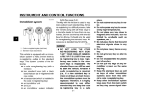
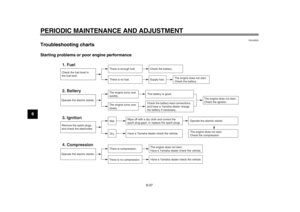
1. Instantaneous fuel consumption display
1
1. Error code display
1
59C-9-E2.book 11 ページ 2013年6月18日 火曜日 午後1時33分
Page 27 of 100

INSTRUMENT AND CONTROL FUNCTIONS
3-12
234
5
6
7
8
9
from starting.2. If the engine starts, turn it off and try starting the engine with the
standard keys.
3. If one or both of the standard keys do not start the engine, take the
vehicle, the code re-registering
key and both standard keys to a
Yamaha dealer and have the stan-
dard keys re-registered.NOTICE
ECA11591
If the display indicates an error
code, the vehicle should be checked
as soon as possible in order to avoidengine damage.
EAU1234F
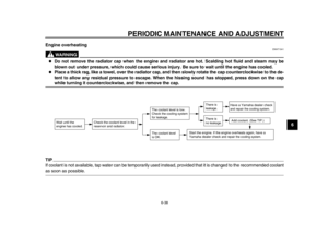
Handlebar switchesLeft Right
EAU12361
Pass switch “PASS”
Press this switch to flash the headlight.
EAU12401
Dimmer switch “ / ”
Set this switch to “ ” for the high
beam and to “ ” for the low beam.
EAU12461
Turn signal switch “ / ”
To signal a right-hand turn, push this
switch to “ ”. To signal a left-hand
turn, push this switch to “ ”. When re-
leased, the switch returns to the center
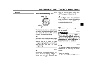
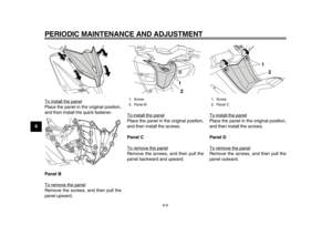
1. Pass switch “PASS”
2. Dimmer switch “ / ”
3. Turn signal switch “ / ”
4. Horn switch “ ”
1
2
3
4
1. Engine stop switch “ / ”
2. Hazard switch “ ”
3. Start switch “ ”
1
2
3
59C-9-E2.book 12 ページ 2013年6月18日 火曜日 午後1時33分
Page 28 of 100

INSTRUMENT AND CONTROL FUNCTIONS
3-13
1
23
4
5
6
7
8
9position. To cancel the turn signal
lights, push the switch in after it has re-
turned to the center position.
EAU12501
Horn switch “ ”
Press this switch to sound the horn.
EAU12661
Engine stop switch “ / ”
Set this switch to “ ” before starting
the engine. Set this switch to “ ” to
stop the engine in case of an emergen-
cy, such as when the vehicle overturns
or when the throttle cable is stuck.
EAU12722
Start switch “ ”
With the sidestand up, push this switch
while applying the front or rear brake to
crank the engine with the starter. See
page 5-1 for starting instructions prior
to starting the engine.
EAU44712
The engine trouble warning light and
ABS warning light (ABS model only)
may come on when the key is turned to
“ON” and the start switch is pushed, but this does not indicate a malfunction.
EAU12734
Hazard switch “ ”
With the key in the “ON” or “ ” posi-
tion, use this switch to turn on the haz-
ard lights (simultaneous flashing of all
turn signal lights).
The hazard lights are used in case of
an emergency or to warn other drivers
when your vehicle is stopped where it
might be a traffic hazard.NOTICE
ECA10062
Do not use the hazard lights for an
extended length of time with the en-
gine not running, otherwise the bat-tery may discharge.
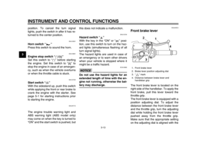
EAU44912
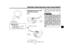
Front brake leverThe front brake lever is located on the
right side of the handlebar. To apply the
front brake, pull this lever toward the
throttle grip.
The front brake lever is equipped with a
position adjusting dial. To adjust the
distance between the front brake lever
and the throttle grip, turn the adjusting
dial while holding the front brake lever
pushed away from the throttle grip.
Make sure that the appropriate setting
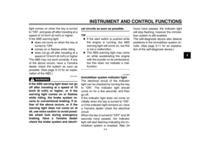
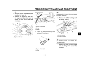
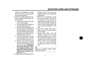
on the adjusting dial is aligned with the1. Front brake lever
2. Brake lever position adjusting dial
3. “ ” mark
4. Distance between brake lever and
handlebar grip
1
4
2
3
59C-9-E2.book 13 ページ 2013年6月18日 火曜日 午後1時33分
Page 29 of 100
INSTRUMENT AND CONTROL FUNCTIONS
3-14
234
5
6
7
8
9
“ ” mark on the front brake lever.
EAU44922
Rear brake leverThe rear brake lever is located at the
left handlebar grip. To apply the rear
brake, pull this lever toward the handle-
bar grip.
The rear brake lever is equipped with a
position adjusting dial
. To adjust the
distance between the rear brake lever
and the handlebar grip, turn the adjust-
ing dial while holding the rear brake le-
ver pushed away from the handlebar
grip. Make sure that the appropriate
setting on the adjusting dial is aligned with the “ ” mark on the rear brake le-
ver.1. Rear brake lever
2. Brake lever position adjusting dial
3. “ ” mark
4. Distance between brake lever and
handlebar grip
54321
32
1
4
59C-9-E2.book 14 ページ 2013年6月18日 火曜日 午後1時33分
Page 30 of 100

INSTRUMENT AND CONTROL FUNCTIONS
3-15
1
23
4
5
6
7
8
9
EAU12963
Rear brake lock leverThis vehicle is equipped with a rear
brake lock lever to prevent the rear
wheel from moving while stopped at
traffic signals, railroad crossings, etc.
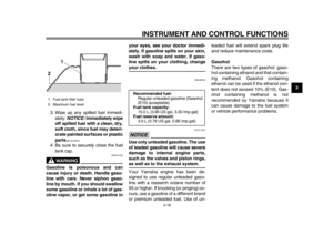
To lock the rear wheel
Push the rear brake lock lever to the left
until it snaps into place.
To unlock the rear wheel
Push the rear brake lock lever back to
the original position.TIP
Be sure to check that the rear
wheel does not move when therear brake lock lever is applied.
To provide secure locking of the
rear wheel, apply the rear brake le-
ver first before moving the rearbrake lock lever to the left.WARNING
EWA12362
Never move the rear brake lock lever
to the left while the vehicle is mov-
ing, otherwise loss of control or an
accident may result. Make sure that
the vehicle is stopped before mov-
ing the rear brake lock lever to theleft.
EAU54001
ABS (for ABS models)The Yamaha ABS (Anti-lock Brake
System) features a dual electronic con-
trol system, which acts on the front and
rear brakes independently.
Operate the brakes with ABS as you
would conventional brakes. If the ABS
is activated, a pulsating sensation may
be felt at the brake levers. In this situa-
tion, continue to apply the brakes and
let the ABS work; do not “pump” the
brakes as this will reduce braking effec-
tiveness.
WARNING
EWA16051
Always keep a sufficient distance
from the vehicle ahead to match the
riding speed even with ABS.
The ABS performs best with
long braking distances.
On certain surfaces, such as
rough or gravel roads, the brak-
ing distance may be longer withthe ABS than without.
The ABS is monitored by an ECU,
which will revert the system to conven-
tional braking if a malfunction occurs.
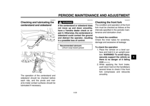
1. Rear brake lock lever
1
59C-9-E2.book 15 ページ 2013年6月18日 火曜日 午後1時33分
Page 31 of 100

INSTRUMENT AND CONTROL FUNCTIONS
3-16
234
5
6
7
8
9
TIP
The ABS performs a self-diagno-
sis test each time the vehicle first
starts off after the key is turned to
“ON” and the vehicle has traveled
at a speed of 10 km/h (6 mi/h) or
higher. During this test, a “clicking”
noise can be heard from the front
of the vehicle, and if either brake
lever is even slightly applied, a vi-
bration can be felt at the lever, but
these do not indicate a malfunc-
tion.
This ABS has a test mode which
allows the owner to experience the
pulsation at the brake levers when
the ABS is operating. However,
special tools are required, so
please consult your Yamaha deal-er when performing this test.
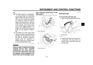
NOTICE
ECA16121
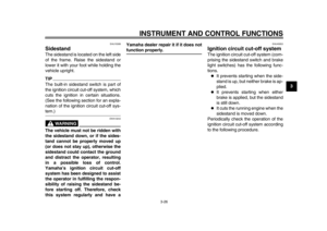
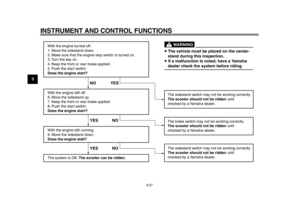
Keep any type of magnets (including
magnetic pick-up tools, magnetic
screwdrivers, etc.) away from the
front and rear wheel hubs, otherwise
the magnetic rotors equipped in the
wheel hubs may be damaged, result- ing in improper performance of the
ABS system.
EAU13176
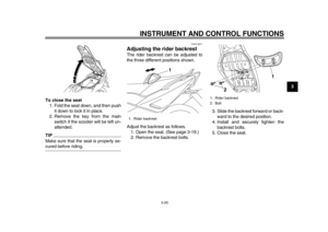
Fuel tank capTo remove the fuel tank cap
1. Open the lid by pulling the lever up.
2. Insert the key into the lock and turn it clockwise. The lock will be re-
leased and the fuel tank cap can
be removed.
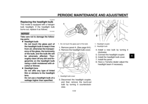
1. Front wheel hub
1. Rear wheel hub
11
1. Opening lever
2. Lid
1
2
59C-9-E2.book 16 ページ 2013年6月18日 火曜日 午後1時33分
Page 32 of 100

INSTRUMENT AND CONTROL FUNCTIONS
3-17
1
23
4
5
6
7
8
9To install the fuel tank cap
1. Align the match marks, insert the fuel tank cap into the tank opening,
and then push down on the cap.
2. Turn the key counterclockwise to the original position, and then re- move it.
3. Close the lid.
WARNING
EWA11262
Make sure that the fuel tank cap is
properly installed and locked in
place before riding the scooter.Leaking fuel is a fire hazard.
EAU13222
FuelMake sure there is sufficient gasoline in
the tank.
WARNING
EWA10882
Gasoline and gasoline vapors are
extremely flammable. To avoid fires
and explosions and to reduce the
risk of injury when refueling, followthese instructions.
1. Before refueling, turn off the en- gine and be sure that no one is sit-
ting on the vehicle. Never refuel
while smoking, or while in the vi-
cinity of sparks, open flames, or
other sources of ignition such as
the pilot lights of water heaters and
clothes dryers.
2. Do not overfill the fuel tank. When refueling, be sure to insert the
pump nozzle into the fuel tank filler
hole. Stop filling when the fuel
reaches the bottom of the filler
tube. Because fuel expands when
it heats up, heat from the engine or
the sun can cause fuel to spill out
of the fuel tank.
1. Fuel tank cap
1. Match marks
1
1
59C-9-E2.book 17 ページ 2013年6月18日 火曜日 午後1時33分