Page 2 of 650

TABLE OF CONTENTSIndex
2
1-1. Key information
Keys ...................................... 38
1-2. Opening, closing and locking
the doors
Smart entry & start system.. 42
Wireless remote control ........ 64
Side doors............................. 73
Back door.............................. 79
1-3. Adjustable components
(seats, mirrors, steering
wheel)
Front seats ............................ 84
Rear seats........................... 86
Head restraints ..................... 94
Seat belts .............................. 96
Steering wheel .................... 104
Anti-glare inside rear view mirror
105
Outside rear view mirrors.... 109
1-4. Opening and closing the win-
dows and panoramic roof
shade
Power windows ................... 112
Panoramic roof shade....... 115
1-5. Refueling
Opening the fuel tank cap ... 118
1-6. Theft deterrent systemEngine immobilizer system 124
Double locking system..... 134
Alarm................................ 136
1-7. Safety information
Correct driving posture ....... 145
SRS airbags ....................... 147
Child restraint systems ....... 158
Installing child restraints ..... 166
Airbag manual on-off system ....
177
2-1. Driving procedures
Driving the vehicle .............. 182
Engine (ignition) switch (vehicles
without smart entry & start sys-
tem) .................................. 196
Engine (ignition) switch (vehicles
with smart entry & start system)
200
Multidrive.......................... 206
Automatic transmission.... 212
Manual transmission........ 220
Turn signal lever................. 224
Parking brake ..................... 225
Horn ................................... 227
2-2. Instrument cluster
Gauges and meters............ 228
Indicators and warning lights.....
233
Multi-information display .... 239
1Before driving
2When driving
VERSO_WE.book Page 2 Thursday, June 19, 2014 11:31 AM
Page 181 of 650

2When driving
181
2-1. Driving procedures
Driving the vehicle ............ 182
Engine (ignition) switch
(vehicles without smart
entry & start system)....... 196
Engine (ignition) switch
(vehicles with smart
entry & start system)....... 200
Multidrive .......................... 206
Automatic transmission .... 212
Manual transmission......... 220
Turn signal lever ............... 224
Parking brake ................... 225
Horn .................................. 227
2-2. Instrument cluster
Gauges and meters .......... 228
Indicators and warning
lights ............................... 233
Multi-information display ... 239
2-3. Operating the lights and
wipers
Headlight switch ............... 251
Fog light switch ................. 258
Windshield wipers and
washer ............................ 259
Rear window wiper and
washer ............................ 2642-4. Using other driving systems
Cruise control.................... 265
Speed limiter ..................... 269
Toyota parking
assist-sensor .................. 272
Stop & Start system .......... 280
Driving assist systems ...... 287
Hill-start assist control....... 293
2-5. Driving information
Cargo and luggage ........... 295
Winter driving tips ............. 298
Trailer towing
(except Morocco) ............ 302
VERSO_WE.book Page 181 Thursday, June 19, 2014 11:31 AM
Page 228 of 650
228
2-2. Instrument cluster
Gauges and meters
Left-hand drive vehicles
Vehicles without smart entry & start system
The following gauges, meters and displays illuminate when the
engine switch is in the “ON” position.
Vehicles with smart entry & start system
The following gauges, meters and displays illuminate when the
“ENGINE START STOP” switch is in IGNITION ON mode.
Tachometer
Displays the engine speed in revolutions per minute
Speedometer
Displays the vehicle speed
Multi-information display
Presents the driver with a variety of driving-related data (P. 239)
Display change button
P. 230
Fuel gauge
Displays the quantity of fuel remaining in the tank
VERSO_WE.book Page 228 Thursday, June 19, 2014 11:31 AM
Page 229 of 650
229 2-2. Instrument cluster
2
When driving
Odometer, trip meter, Stop & Start system operation time, Stop &
Start system total operation time, maintenance required informa-
tion and instrument panel light control display
P. 230
Right-hand drive vehicles
Vehicles without smart entry & start system
The following gauges, meters and displays illuminate when the
engine switch is in the “ON” position.
Vehicles with smart entry & start system
The following gauges, meters and displays illuminate when the
“ENGINE START STOP” switch is in IGNITION ON mode.
Multi-information display
Presents the driver with a variety of driving-related data (P. 239)
Speedometer
Displays the vehicle speed
Tachometer
Displays the engine speed in revolutions per minute
VERSO_WE.book Page 229 Thursday, June 19, 2014 11:31 AM
Page 230 of 650
230 2-2. Instrument cluster
Changing the display
Items displayed can be switched by pressing the button.
Odometer
Displays the total distance the vehicle has been driven.
Trip meter A
Displays the distance the vehicle has been driven since the meter
was last reset.
Pressing and holding the button will reset.
Odometer, trip meter, Stop & Start system operation time, Stop &
Start system total operation time, maintenance required informa-
tion and instrument panel light control display
P. 230
Fuel gauge
Displays the quantity of fuel remaining in the tank
Display change button
P. 230
VERSO_WE.book Page 230 Thursday, June 19, 2014 11:31 AM
Page 231 of 650

231 2-2. Instrument cluster
2
When driving
Trip meter B
Displays the distance the vehicle has been driven since the meter
was last reset.
Press and hold the button will reset.
Stop & Start system operation time (if equipped)
Displays the amount of time the engine was stopped due to opera-
tion of the Stop & Start system during the current trip.
Vehicles without smart entry & start system:
From the engine switch in the “ON” position to the engine switch in
the “LOCK” position.
Vehicles with smart entry & start system:
From the “ENGINE START STOP” switch in IGNITION ON mode
to the “ENGINE START STOP” switch off.
Stop & Start system total operation time (if equipped)
Displays the total amount of time that the engine has been stopped
due to operation of the Stop & Start system since the system was
last reset.
Maintenance required information (1WW-FHV engine only)
Displays the remaining distance until the engine oil should be
changed. If “-” is displayed before distance, it means oil mainte-
nance is overdue. Have the engine oil changed by any authorized
Toyota dealer or repairer, or another duly qualified and equipped
professional.
• Displays the Maintenance required information when the engine switch
is turned to the “ON” position (vehicles without smart entry & start sys-
tem) or the “ENGINE START STOP” is switched to IGNITION ON mode
(vehicles with smart entry & start system).
• Maintenance required information reset method (P. 428).
VERSO_WE.book Page 231 Thursday, June 19, 2014 11:31 AM
Page 232 of 650

232 2-2. Instrument cluster
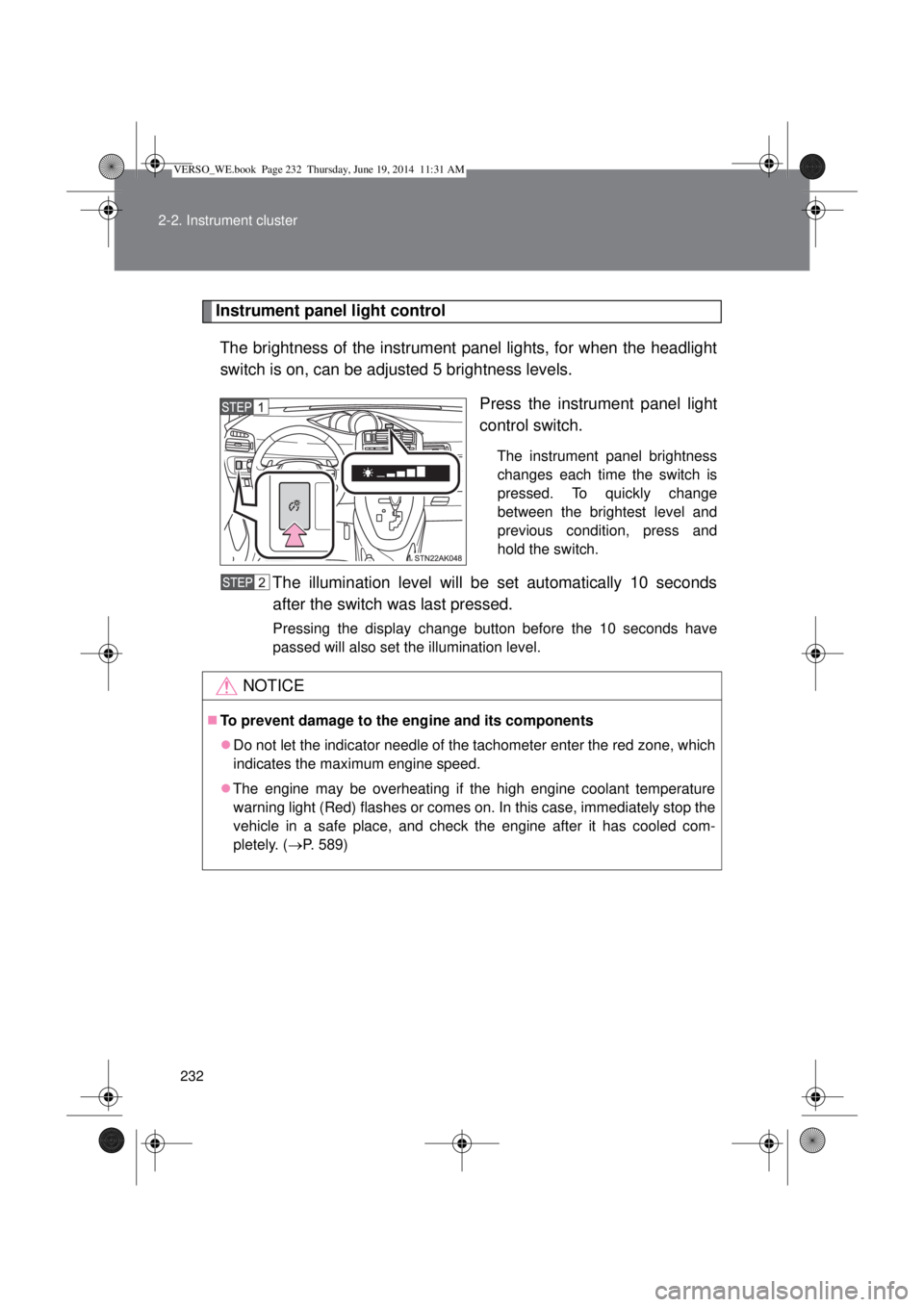
Instrument panel light control
The brightness of the instrument panel lights, for when the headlight
switch is on, can be adjusted 5 brightness levels.
Press the instrument panel light
control switch.
The instrument panel brightness
changes each time the switch is
pressed. To quickly change
between the brightest level and
previous condition, press and
hold the switch.
The illumination level will be set automatically 10 seconds
after the switch was last pressed.
Pressing the display change button before the 10 seconds have
passed will also set the illumination level.
NOTICE
To prevent damage to the engine and its components
Do not let the indicator needle of the tachometer enter the red zone, which
indicates the maximum engine speed.
The engine may be overheating if the high engine coolant temperature
warning light (Red) flashes or comes on. In this case, immediately stop the
vehicle in a safe place, and check the engine after it has cooled com-
pletely. (P. 589)
VERSO_WE.book Page 232 Thursday, June 19, 2014 11:31 AM
Page 233 of 650
233
2-2. Instrument cluster
2
When driving
Indicators and warning lights
The indicator and warning lights on the instrument cluster and cen-
ter panel inform the driver of the status of the vehicle’s various sys-
tems.
For the purpose of explanation, the following illustration displays all
indicators and warning lights illuminated.
Instrument cluster (Left-hand drive vehicles)*
Instrument cluster (Right-hand drive vehicles)*
*
: The units used on the speedometer, tachometer and some indicators
may differ depending on the engine, transmission, etc.
VERSO_WE.book Page 233 Thursday, June 19, 2014 11:31 AM