2014 SUBARU TRIBECA turn signal
[x] Cancel search: turn signalPage 162 of 426
&Daytime running light system
WARNING
The brightness of the illumination ofthe high beam headlights is reducedby the daytime running light system.The light switch must always beturned to the“”position when itis dark outside.
The high beam headlights will automati-cally illuminate at reduced brightnesswhen the engine has started, under thefollowing conditions.
.The select lever is in a position otherthan the“P”position.
.The parkingbrake is fully released.
.The light switch is in the“OFF”or“”position.
NOTE
When the light switch is in the“”position,the front side marker lights,parking lights and license plate lightsare also illuminated.
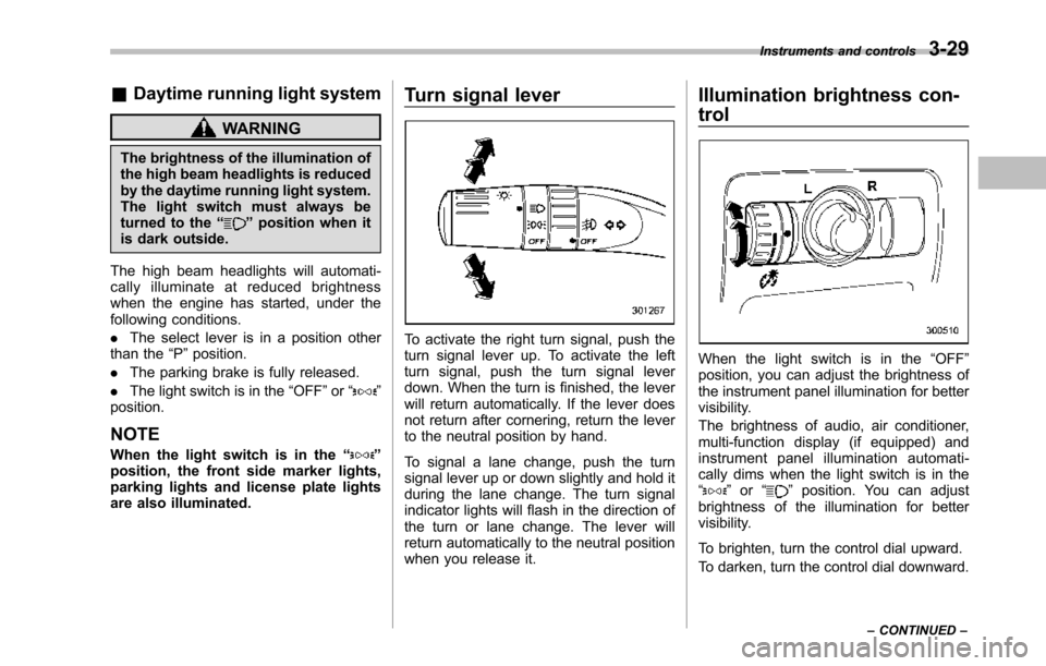
Turn signal lever
To activate the right turn signal, push theturn signal lever up. To activate the leftturn signal, push the turn signal leverdown. When the turn is finished, the leverwill return automatically. If the lever doesnot return after cornering, return the leverto the neutral position by hand.
To signal a lane change, push the turnsignal lever up or down slightly and hold itduring the lane change. The turn signalindicator lights will flash in the direction ofthe turn or lane change. The lever willreturn automatically to the neutral positionwhen you release it.
Illumination brightness con-
trol
When the light switch is in the“OFF”position, you can adjust the brightness ofthe instrument panel illumination for bettervisibility.
The brightnessof audio, air conditioner,multi-function display (if equipped) andinstrument panel illumination automati-cally dims when the light switch is in the“”or“”position. You can adjustbrightness of the illumination for bettervisibility.
To brighten, turn the control dial upward.
To darken, turn the control dial downward.
Instruments and controls3-29
–CONTINUED–
Page 165 of 426
3-32Instruments and controls
Parking light switch
The parking light switch operates regard-less of the ignition switch position.
By pushing the front end of this switch,following lights will illuminate.
–Parking lights
–Front and rear side marker lights
–Tail lights
–License plate lights
To turn off, push the rear end of theparking lightswitch.
Avoid leaving these lights on for a longtime because that will run down thebattery.
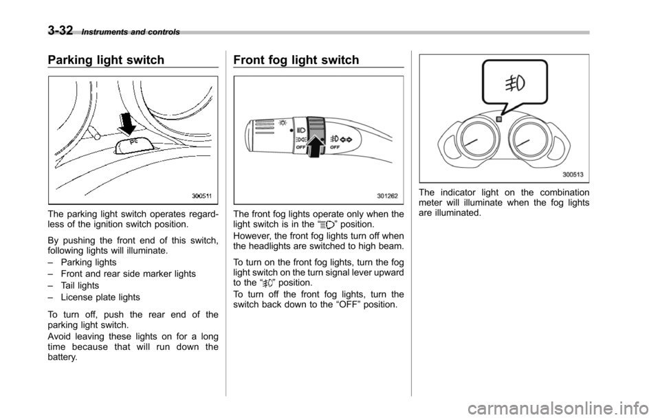
Front fog light switch
The front fog lights operate only when thelight switch is in the“”position.
However, the front fog lights turn off whenthe headlights are switched to high beam.
To turn on the front fog lights, turn the foglight switchon the turn signal lever upwardto the“”position.
To turn off the front fog lights, turn theswitch back down to the“OFF”position.
The indicator light on the combinationmeter will illuminate when the fog lightsare illuminated.
Page 199 of 426
5-8Audio
!Sirius XMTMSatellite Radio Acti-vation (for U.S.A. only)
Models with Sirius XMTMare eligible for a3-month complimentary subscription tothe Sirius XMTMSatellite Radio service.
Activation process:
You can activate the XM Satellite Radiofromthe website of the XM Satellite Radio.For details, visit the website.
!Satellite radio reception
Satellite radio signals are best received inareas with a clear view of the open sky. Inareas wherethere are tall buildings, trees,tunnels or other structures that mayobstruct the signal of the satellites, theremay be signal interruptions. Other circum-stances that may result in signal lossinclude driving near a wall, steep cliff orhill, or driving on the lower level of a multi-tiered road or inside a parking garage.
To help reduce this condition, satelliteradio providers have installed ground-based repeaters in heavily populatedareas. However, you may still experiencereception problems in some areas.
!Displaying satellite radio ID oftuner
When you activate satellite radio, youshould have your satellite radio tuner ID
ready because each tuner is identified byits unique satellite radio tuner ID.
The satellite radio ID will be needed whenyou activate satellite radio and receivesatellite radio customer support.
The satellite radio ID can be found on theaudio display by tuning the channel to“0”.
Turn the“TUNE TRACK”button (4) toselect the satellite radio channel.
!Band selection button
Push the“SAT”button (1) when the radiois off to turn on the radio.
Push the“SAT”button when the radio ison to select SAT1, SAT2 or SAT3 recep-tion.
!Channel selection
Press“”of the“TUNE TRACK”button(4) to select the next channel and press“”of the button to select the previouschannel.
Keep pressing“”of the button tochange to the next channel continuouslyand keep pressing“”of the button tochange to the previous channel continu-ously.
!Category selection
Press“”or“”of the“SEEK FLDR”button (7) to display the current category.Press“”again to select the next
category, and press“”again to selectthe previous category.
!Channel scan
Press the“SCAN”button (8) to change theradio to the SCAN mode. In this mode, theradio scans through the channels until astation is found. The radio will stop at thestation for 5 seconds while displaying thechannel number, after which scanning willcontinue until the entire channel has beenscanned from the low end to the high end.
Also during the category selection, chan-nel scan can be performed in that cate-gory.
Press the“SCAN”button again to cancelthe SCAN mode and to stop on anydisplayed channel.
!Selecting presetchannels
Presetting a channel with a preset button(10) allows you to select that channel in asingle operation. Up to six, SAT1, SAT2and SAT3 channels each may be preset.
!How to preset channels
1. Press the“SAT”button (1) to selectSAT1, SAT2 and SAT3 reception.
2. Press the“SCAN”button (8) or the“TUNE TRACK”button (4) to select thechannel.
3. Press and hold one of the preset
Page 263 of 426
7-16Starting and operating
1) Shift lock release button2) Select lever button
3. Move the select lever while performingthefollowing operations..Depressing the brake pedal.Pushing the shift lock release buttonusing a screwdriver.Pushing the select lever button
If the select lever does not move afterperforming the above procedure, the shiftlock system may be malfunctioning. Con-tact a SUBARU dealer for an inspectionas soon as possible.
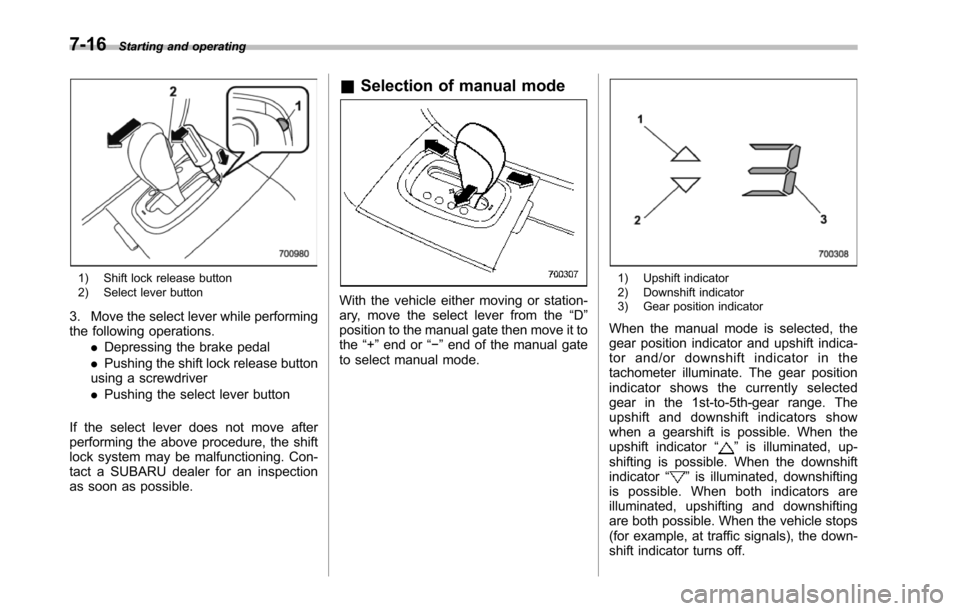
&Selection of manual mode
With the vehicle either moving or station-ary, move the select lever from the“D”position to the manual gate then move it tothe“+”end or“!”end of the manual gateto select manual mode.
1) Upshift indicator2) Downshift indicator3) Gear position indicator
When themanual mode is selected, thegear position indicator and upshift indica-tor and/or downshift indicator in thetachometer illuminate. The gear positionindicator shows the currently selectedgear in the 1st-to-5th-gear range. Theupshift and downshift indicators showwhen a gearshift is possible. When theupshiftindicator“”is illuminated, up-shifting is possible. When the downshiftindicator“”is illuminated, downshiftingis possible. When both indicators areilluminated, upshifting and downshiftingare both possible. When the vehicle stops(for example, at traffic signals), the down-shift indicator turns off.
Page 274 of 426

Tire pressure monitoring
system (TPMS)
The tire pressure monitoring system pro-vides the driver with a warning messageby sending a signal from a sensor that isinstalled in each wheel when tire pressureis severely low.
The tire pressure monitoring system willactivate only when the vehicle is driven atspeeds above 20 mph (32 km/h). Also,this system may not react immediately to asudden drop in tire pressure (for example,a blow-out caused by running over asharp object).
WARNING
If the low tire pressure warning lightilluminates while driving, neverbrake suddenly and keep drivingstraight ahead while gradually redu-cing speed. Then slowly pull off theroad to a safe place. Otherwise anaccident involving serious vehicledamage and serious personal injurycould occur.
Check the pressure for all four tiresand adjust the pressure to the COLDtire pressure shown on the tireplacard on the door pillar on thedriver’s side.
Even when the vehicle is driven avery short distance, the tires getwarm and their pressures increaseaccordingly. Be sure to let the tirescool thoroughly before adjustingtheir pressures to the standardvalues shown on the tire placard.Refer to“Tires and wheels”F11-21.The tire pressure monitoring systemdoes not function when the vehicleis stationary. After adjusting the tirepressures, increase the vehiclespeed to at least 20 mph (32 km/h)to start the TPMS re-checking of thetire inflation pressures. If the tirepressures are now above the severe
low pressure threshold, the low tirepressure warning light should turnoff a few minutes later.
If this light still illuminates whiledriving after adjusting the tire pres-sure, a tire may have significantdamage and a fast leak that causesthe tire to lose air rapidly. If you havea flat tire, replace it with a spare tireas soon as possible.
When a spare tire is mounted or awheel rim is replaced without theoriginal pressure sensor/transmitterbeing transferred, the low tire pres-sure warning light will illuminatesteadily after blinking for approxi-mately one minute. This indicatesthe TPMS is unable to monitor allfour road wheels. Contact yourSUBARU dealeras soon as possiblefor tire and sensor replacement and/or system resetting.
Do not inject any tire liquid oraerosol tire sealant into the tires,as this may cause a malfunction ofthe tire pressure sensors. If the lightilluminates steadily after blinking forapproximately one minute, promptlycontact a SUBARU dealer to havethe system inspected.
Starting and operating7-27
–CONTINUED–
Page 299 of 426
8-20Driving tips
5. Use only a hitch ball that is appropriatefor the ball mount and your trailer. Thehitch ball must be securely installed on theball mount.
6. Connect your trailer to the hitch ball.
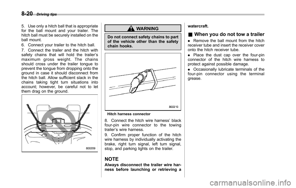
7. Connect the trailer and the hitch withsafety chains that will hold the trailer’smaximum gross weight. The chainsshould cross under the trailer tongue toprevent the tongue from dropping onto theground in case it should disconnect fromthe hitch ball. Allow sufficient slack in thechains taking tight turn situations intoaccount; however, be careful not to letthem drag on the ground.
WARNING
Do not connect safety chains to partof the vehicle other than the safetychain hooks.
Hitch harness connector
8. Connect the hitch wire harness’blackfour-pin wire connector to the towingtrailer’s wire harness.
9. Confirm proper function of the hitchwire harness by individually activating thebrake, right turn signal, left turn signal,stop,and parking lights on the trailer.
NOTE
Always disconnectthe trailer wire har-ness before launching or retrieving a
watercraft.
&When you do not tow a trailer
.Remove the ball mount from the hitchreceiver tube and insert the receiver coveronto the hitch receiver tube.
.Place the dust cap over the four-pinconnectorof the hitch wire harness toprotect against possible damage.
.Occasionally lubricate terminals of thefour-pin connector using the terminalgrease.
Page 305 of 426
8-26Driving tips
blind spots occur with the vehicle’s stan-dard side mirrors, use towing mirrors thatconform with Federal, state/province and/or other applicable regulations.
!Trailer lights
CAUTION
Direct splicing or other improperconnection of trailer lights maydamage your vehicle’selectricalsystem and cause a malfunction ofyour vehicle’s lighting system.
Connection of trailer lights to your vehi-cle’s electrical system requires modifica-tions to the vehicle’s lighting circuit toincrease its capacity and accommodatewiring changes. To ensure the trailer lightsare connected properly, please consultyour SUBARU dealer. Check for properoperation of the turn signals, stop lightsand parking lights each time you hitch up.
!Tires
WARNING
Never tow a trailer when the tem-porary spare tire is used. The tem-porary spare tire is not designed tosustain the towing load. Use of thetemporary spare tire when towing
can result in failure of the spare tireand/or less stability of the vehicle.
Make sure that all the tires on your vehicleare properly inflated. Refer to“Tires”F12-8.
Trailer tire condition, size, load rating andproper inflation pressure should be inaccordance with the trailer manufacturer’sspecifications.
In the event your vehicle gets a flat tirewhen towing a trailer, ask a commercialroad service to repair the flat tire.
If you carry a regular size spare tire in yourvehicle or trailer as a precaution againstgetting a flat tire, be sure that the sparetire is firmly secured.
&Trailer towing tips
CAUTION
.Never exceed 45 mph (72 km/h)when towing a trailer in hillycountry on hot days.
.When towing a trailer, steering,stability, stopping distance andbraking performance will be dif-ferent from normal operation. Forsafety’s sake, you should employ
extra caution when towing atrailer and you should neverspeed. You should also keep thefollowing tips in mind:
!Before starting out on a trip
.Check that the vehicle and vehicle-to-hitch mounting are in good condition. Ifany problems are apparent, do not tow thetrailer.
.Check that the vehicle sits horizontallywith the trailer attached. If the vehicle istippedsharply up at the front and down atthe rear, check the total trailer weight,GVW, GAWs and tongue load again, thenconfirm that the load and its distributionare acceptable.
.Check that the tire pressures arecorrect.
.Checkthat the vehicle and trailer areconnected properly. Confirm that–the trailer tongue is connectedproperly to the hitch ball.–the trailer lights connector is con-nected properly and trailer’s stop lightsilluminate when the vehicle’s brakepedal is pressed, and that the trailer’sturn signal lights flash when thevehicle’s turn signal lever is operated.–the safety chains are connectedproperly.
Page 309 of 426
9-2In case of emergency
If you park your vehicle in an
emergency
The hazard warning flasher should beused in day or night to warn other driverswhen you have to park your vehicle underemergency conditions.
Avoid stopping on the road. It is best tosafely pull off the road if a problem occurs.
The hazard warning flasher can be acti-vated regardless of the ignition switchposition.
Turn on the hazard warning by pushingthe hazard warning flasher switch. Turn itoff by pushing the switch again.
NOTE
When the hazard warning flasher is on,the turn signals do not work.
Spare tire
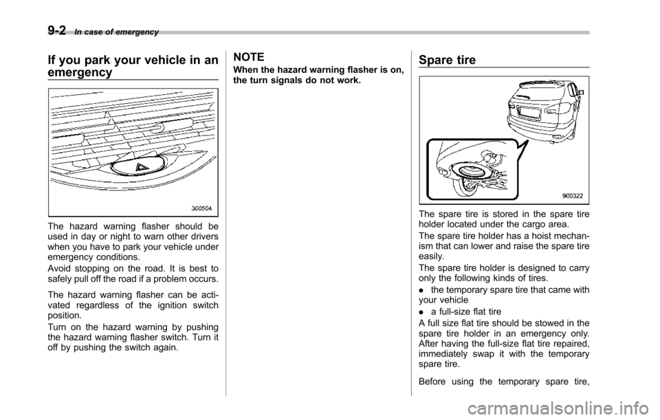
The spare tire is stored in the spare tireholder located under the cargo area.
The spare tire holder has a hoist mechan-ism that can lower and raise the spare tireeasily.
The sparetire holder is designed to carryonly the following kinds of tires.
.the temporary spare tire that came withyour vehicle
.a full-size flat tire
A full size flat tire should be stowed in thespare tire holder in an emergency only.After having the full-size flat tire repaired,immediately swap it with the temporaryspare tire.
Before using the temporary spare tire,