2014 SUBARU TRIBECA turn signal
[x] Cancel search: turn signalPage 317 of 426

9-10In case of emergency
holder.
Refer to“Spare tire”F9-2 for its location,instructions and precautions.
CAUTION
.When stowing a flat tire in thespare tire holder, turn the hoistshaft end only slowly. If it isturned quickly, the wheel disc ofthe flat tire could be damaged.
.Afull-sizeflattireshouldbestowed in the spare tire holderin an emergency only. After hav-ing the flat tire repaired, immedi-ately swap it with the temporaryspare tire.
.Remember that the tread width ofa flat tire is wider than that of thetemporary spare tire. When car-rying a flat tire stowed in thespare tire holder, make sure thetire does not touch any obsta-cles.
WARNING
Never place a tire or tire changingtools in the passenger compartmentafter changing wheels. In a suddenstop or collisions, loose equipment
could strike occupants and causeinjury. Store the tire and all tools inthe proper place.
&Tire pressure monitoring
system (TPMS)
The tire pressure monitoring system pro-vides the driver with the warning messageindicated by sending a signal from asensor that is installed in each wheelwhen tire pressure is severely low.
The tire pressure monitoring system willactivate only when the vehicle is driven.Also, this system may not react immedi-ately to a sudden drop in tire pressure (forexample, a blow-out caused running overa sharp object).
WARNING
If the low tire pressure warning lightilluminates while driving, neverbrake suddenly and keep drivingstraight ahead while gradually redu-cing speed. Then slowly pull off theroad to a safe place. Otherwise anaccident involving serious vehicledamageand serious personal injurycould occur.
Check the pressure for all four tiresand adjust the pressure to the COLDtire pressure shown on the vehicleplacard on the door pillar on thedriver’s side. If this light still illumi-nates while driving after adjustingthe tire pressure, a tire may havesignificant damage and a fast leakthat causes the tire to lose airrapidly. If you have a flat tire, replaceit with a spare tire as soon aspossible.
When a spare tire is mounted or awheel rim is replaced without theoriginal pressure sensor/transmitterbeing transferred, the low tire pres-sure warning light will illuminatesteadily afterblinking for approxi-mately one minute. This indicatesthe TPMS is unable to monitor allfour road wheels. Contact your
Page 335 of 426
Maintenance and service
Rear window wiper blade rubber....................... 11-31
Battery............................................................... 11-33
Fuses................................................................ 11-34
Main fuse.......................................................... 11-35
Installation of accessories............................... 11-36
Replacing bulbs............................................... 11-36Headlights(models with HID headlights)........... 11-36Headlights (models without HID headlights) ...... 11-36Parking light (right-hand side)........................... 11-38Front turn signal light (right-hand side)............. 11-39
Front fog light.................................................. 11-39Rear combination lights................................... 11-39Backup light/Tail light...................................... 11-40Rear gate light................................................. 11-41License plate light........................................... 11-41Dome light....................................................... 11-42Map light......................................................... 11-43Vanity mirror light............................................ 11-43Door step light................................................. 11-43Cargo area light............................................... 11-44
Page 354 of 426
Tires and wheels
&Types of tires
You should be familiar with type of tirespresent on your vehicle.
!All season tires
The factory-installed tires on your newvehicle are all season tires.
All season tires are designed to providean adequate measure of traction, handlingand braking performance in year-rounddriving including snowy and icy roadconditions. However all season tires donot offer as much traction performance aswinter (snow) tires in heavy or loose snowor on icy roads.
All season tires are identified by“ALLSEASON”and/or“M+S”(Mud & Snow) onthe tire sidewall.
!Summer tires
Summer tires are high-speed capabilitytires best suited for highway driving underdry conditions.
Summer tires are inadequate for drivingon slippery roads such as on snow-covered or icy roads.
If you drive your vehicle on snow-coveredor icy roads, we strongly recommend theuse of winter (snow) tires.
When installing winter tires, be sure to
replace all four tires.
!Winter (snow) tires
Winter tires are best suited for driving onsnow-covered and icy roads. Howeverwinter tires do not perform as well assummer tires and all season tires on roadsother than snow-covered and icy roads.
&Tire pressure monitoring
system (TPMS)
The tire pressure monitoring system pro-vides the driver with a warning messageby sending a signal from a sensor that isinstalled in each wheel when tire pressureis severely low. The tire pressure monitor-ing system will activate only when thevehicle is driven. Also, this system maynot react immediately to a sudden drop intire pressure (for example, a blow-outcausedby running over a sharp object).
If you adjust the tire pressures in a warmgarage and will then drive the vehicle incold outside air, the resulting drop in tirepressures may cause the low tire pressurewarning light to illuminate. To avoid thisproblem when adjusting the tire pressuresin a warm garage, inflate the tires topressures higher than those shown on thetire placard. Specifically, inflate them by anextra 1 psi (6.9 kPa, 0.07 kgf/cm2) forevery difference of 108F (5.68C) between
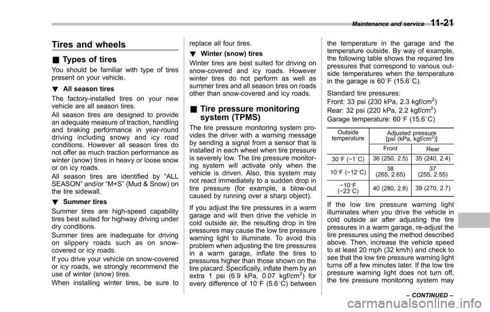
the temperature in the garage and thetemperature outside. By way of example,the following table shows the required tirepressures that correspond to various out-side temperatures when the temperaturein the garage is 608F (15.68C).
Standard tire pressures:
Front: 33 psi (230 kPa, 2.3 kgf/cm2)
Rear: 32 psi (220 kPa, 2.2 kgf/cm2)
Garage temperature: 608F (15.68C)
OutsidetemperatureAdjusted pressure[psi (kPa, kgf/cm2)]
FrontRear
308F(!18C)36 (250, 2.5) 35 (240, 2.4)
108F(!128C)38(265, 2.65)37(255, 2.55)
!108F(!238C)40 (280, 2.8)39 (270, 2.7)
If the low tire pressure warning lightilluminates when you drive the vehicle incold outside air after adjusting the tirepressures in a warm garage, re-adjust thetire pressures using the method describedabove. Then, increase the vehicle speedto at least 20 mph (32 km/h) and check tosee that the low tire pressure warning lightturns off a few minutes later. If the low tirepressure warning light does not turn off,the tire pressure monitoring system may
Maintenance and service11-21
–CONTINUED–
Page 372 of 426
&Front turn signal light (right-
hand side)
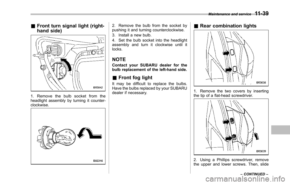
1. Remove the bulb socket from theheadlight assembly by turning it counter-clockwise.
2. Remove the bulb from the socket bypushing it and turning counterclockwise.
3. Install a new bulb.
4. Set the bulb socket into the headlightassembly and turn it clockwise until itlocks.
NOTE
Contact your SUBARU dealer for thebulb replacement of the left-hand side.
&Front fog light
It may be difficult to replace the bulbs.Have the bulbs replaced by your SUBARUdealer if necessary.
&Rear combination lights
1. Remove the two covers by insertingthe tip of a flat-head screwdriver.
2. Using a Phillips screwdriver, removethe upper and lower screws. Then, slide
Maintenance and service11-39
–CONTINUED–
Page 373 of 426
11-40Maintenance and service
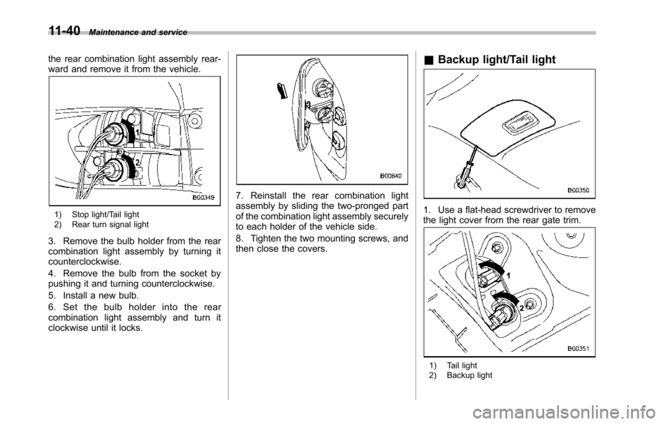
the rear combination light assembly rear-ward and remove it from the vehicle.
1) Stop light/Tail light2) Rear turn signal light
3. Remove the bulb holder from the rearcombination light assembly by turning itcounterclockwise.
4. Remove the bulb from the socket bypushing it and turning counterclockwise.
5. Install a new bulb.
6. Set the bulb holder into the rearcombination light assembly and turn itclockwise until it locks.
7. Reinstall the rear combination lightassembly by sliding the two-pronged partof the combination light assembly securelyto each holder of the vehicle side.
8. Tighten the two mounting screws, andthen close the covers.
&Backup light/Tail light
1. Use a flat-head screwdriver to removethe light cover from the rear gate trim.
1) Tail light2) Backup light
Page 386 of 426
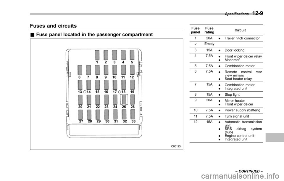
Fuses and circuits
&Fuse panel located in the passenger compartment
FusepanelFuseratingCircuit
1 20A.Trailer hitch connector
2Empty
3 15A.Door locking
4 7.5A.Front wiper deicer relay.Moonroof
5 7.5A.Combination meter
6 7.5A.Remote control rearview mirrors.Seat heater relay
7 15A.Combination meter.Integrated unit
8 15A.Stop light
9 20A.Mirror heater.Front wiper deicer
10 7.5A.Power supply (battery)
11 7.5A.Turn signal unit
12 15A.Automatic transmissionunit.SRS airbag system(sub).Engine control unit.Integrated unit
Specifications12-9
–CONTINUED–
Page 390 of 426
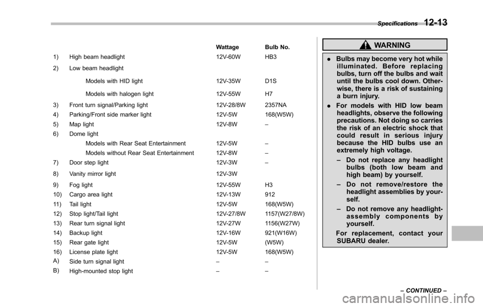
Wattage Bulb No.
1) High beam headlight 12V-60W HB3
2) Low beam headlight
Models with HID light 12V-35W D1S
Models with halogen light 12V-55W H7
3) Front turn signal/Parking light 12V-28/8W 2357NA
4) Parking/Front side marker light 12V-5W 168(W5W)
5) Map light 12V-8W–
6) Dome light
Models with Rear Seat Entertainment 12V-5W–
Models without Rear Seat Entertainment 12V-8W–
7) Door step light 12V-3W–
8) Vanity mirror light 12V-3W
9) Fog light 12V-55W H3
10) Cargo area light 12V-13W 912
11) Tail light 12V-5W 168(W5W)
12) Stop light/Tail light12V-27/8W 1157(W27/8W)
13) Rear turn signal light12V-27W1156(W27W)
14) Backup light 12V-16W 921(W16W)
15) Rear gate light 12V-5W (W5W)
16) License plate light 12V-5W 168(W5W)
A)Side turn signal light––
B)High-mounted stop light––
WARNING
.Bulbs may become very hot whileilluminated. Before replacingbulbs, turn off the bulbs and waituntil the bulbs cool down. Other-wise, there is a risk of sustaininga burn injury.
.For models with HID low beamheadlights, observe the followingprecautions.Not doing so carriesthe risk of an electric shock thatcould result in serious injurybecause the HID bulbs use anextremely high voltage.
–Do not replace any headlightbulbs (both low beam andhigh beam) by yourself.
–Do not remove/restore theheadlight assemblies by your-self.
–Do not remove any headlight-assembly components byyourself.
For replacement, contact yourSUBARU dealer.
Specifications12-13
–CONTINUED–
Page 414 of 426
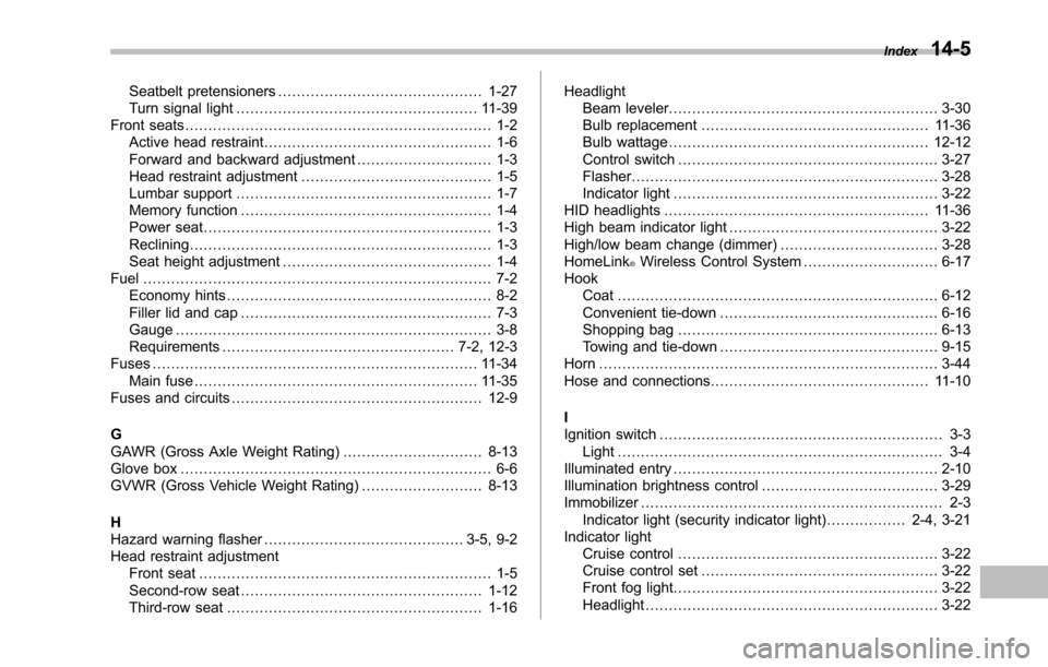
Seatbelt pretensioners............................................ 1-27Turn signal light.................................................... 11-39Front seats.................................................................. 1-2Active head restraint................................................. 1-6Forward and backward adjustment............................. 1-3Head restraint adjustment......................................... 1-5Lumbar support....................................................... 1-7Memory function...................................................... 1-4Power seat.............................................................. 1-3Reclining................................................................. 1-3Seat height adjustment............................................. 1-4Fuel........................................................................... 7-2Economy hints......................................................... 8-2Filler lid and cap...................................................... 7-3Gauge.................................................................... 3-8Requirements.................................................. 7-2, 12-3Fuses...................................................................... 11-34Main fuse............................................................. 11-35Fuses and circuits...................................................... 12-9
GGAWR (Gross Axle Weight Rating).............................. 8-13Glove box................................................................... 6-6GVWR (Gross Vehicle Weight Rating).......................... 8-13
HHazard warning flasher........................................... 3-5, 9-2Head restraint adjustmentFront seat............................................................... 1-5Second-row seat.................................................... 1-12Third-row seat....................................................... 1-16
HeadlightBeam leveler.......................................................... 3-30Bulb replacement................................................. 11-36Bulb wattage........................................................ 12-12Control switch........................................................ 3-27Flasher.................................................................. 3-28Indicator light......................................................... 3-22HID headlights......................................................... 11-36High beam indicator light............................................. 3-22High/low beam change (dimmer).................................. 3-28HomeLink®Wireless Control System............................. 6-17HookCoat..................................................................... 6-12Convenienttie-down............................................... 6-16Shopping bag........................................................ 6-13Towing and tie-down............................................... 9-15Horn......................................................................... 3-44Hose and connections............................................... 11-10
IIgnition switch............................................................. 3-3Light...................................................................... 3-4Illuminated entry......................................................... 2-10Illumination brightness control...................................... 3-29Immobilizer................................................................. 2-3Indicator light (security indicator light)................. 2-4, 3-21Indicator lightCruise control........................................................ 3-22Cruise control set................................................... 3-22Front fog light......................................................... 3-22Headlight............................................................... 3-22
Index14-5