2014 SUBARU IMPREZA WRX air conditioning
[x] Cancel search: air conditioningPage 154 of 414

other similar items. Periodically wipe the
sensors clean using a piece of dry soft
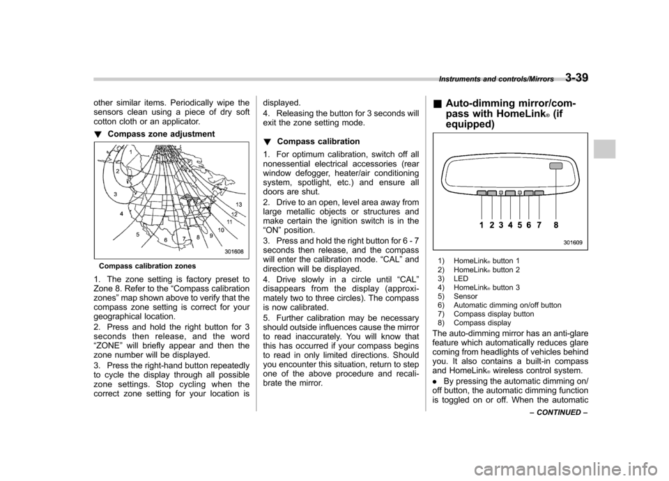
cotton cloth or an applicator. !Compass zone adjustment
Compass calibration zones
1. The zone setting is factory preset to
Zone 8. Refer to the “Compass calibration
zones ”map shown above to verify that the
compass zone setting is correct for your
geographical location.
2. Press and hold the right button for 3
seconds then release, and the word“ ZONE ”will briefly appear and then the
zone number will be displayed.
3. Press the right-hand button repeatedly
to cycle the display through all possible
zone settings. Stop cycling when the
correct zone setting for your location is displayed.
4. Releasing the button for 3 seconds will
exit the zone setting mode. !
Compass calibration
1. For optimum calibration, switch off all
nonessential electrical accessories (rear
window defogger, heater/air conditioning
system, spotlight, etc.) and ensure all
doors are shut.
2. Drive to an open, level area away from
large metallic objects or structures and
make certain the ignition switch is in the“ ON ”position.
3. Press and hold the right button for 6 - 7
seconds then release, and the compass
will enter the calibration mode. “CAL ”and
direction will be displayed.
4. Drive slowly in a circle until “CAL ”
disappears from the display (approxi-
mately two to three circles). The compass
is now calibrated.
5. Further calibration may be necessary
should outside influences cause the mirror
to read inaccurately. You will know that
this has occurred if your compass begins
to read in only limited directions. Should
you encounter this situation, return to step
one of the above procedure and recali-
brate the mirror. &
Auto-dimming mirror/com-
pass with HomeLink
®(if
equipped)
1) HomeLink®button 1
2) HomeLink®button 2
3) LED
4) HomeLink
®button 3
5) Sensor
6) Automatic dimming on/off button
7) Compass display button
8) Compass display
The auto-dimming mirror has an anti-glare
feature which automatically reduces glare
coming from headlights of vehicles behind
you. It also contains a built-in compass
and HomeLink
®wireless control system.
. By pressing the automatic dimming on/
off button, the automatic dimming function
is toggled on or off. When the automatic
Instruments and controls/Mirrors3-39
– CONTINUED –
Page 166 of 414

Ventilator.............................................................. 4-2
Airflow selection ................................................. 4-2
Center and side ventilators .................................. 4-3
Manual climate control system (if equipped) .......................................................... 4-3
Control panel ...................................................... 4-3
Heater operation ................................................. 4-5
Air conditioner operation ..................................... 4-7
Automatic climate control system (if equipped) .......................................................... 4-8
Control panel ...................................................... 4-8
To use as full-automatic climate control system .............................................................. 4-8
To use as semi-automatic climate control system .............................................................. 4-8
Fan speed control dial ......................................... 4-9
Temperature control dial ...................................... 4-9
Airflow control dial .............................................. 4-9
Air inlet selection button .................................... 4-10 Air conditioner button
........................................ 4-11
Temperature sensors ......................................... 4-11
Operating tips for heater and air conditioner ...................................................... 4-12
Cleaning ventilation grille ................................... 4-12
Efficient cooling after parking in direct sunlight ........................................................... 4-12
Lubrication oil circulation in the refrigerant circuit .............................................................. 4-12
Checking air conditioning system before summer season ............................................................ 4-12
Cooling and dehumidifying in high humidity and low temperature weather conditions ................. 4-12
Air conditioner compressor shut-off when engine is heavily loaded .............................................. 4-13
Refrigerant for your climate control system ... ..... 4-13
Air filtration system ........................................... 4-13
Replacing an air filter ......................................... 4-13Climate control
4
Page 177 of 414

4-12Climate control/Operating tips for heater and air conditioner
properly and become damaged, the sys-
tem may not be able to control the interior
temperature correctly. To avoid damaging
the sensors, observe the following pre-cautions. –Do not subject the sensors to impact.
– Keep water away from the sensors.
– Do not cover the sensors.
The sensors are located as follows.– Solar sensor: beside the windshield
defroster grille.– Interior air temperature sensor: near
the ignition switch.– Outside temperature sensor: behind
the front grille. Operating tips for heater and
air conditioner &
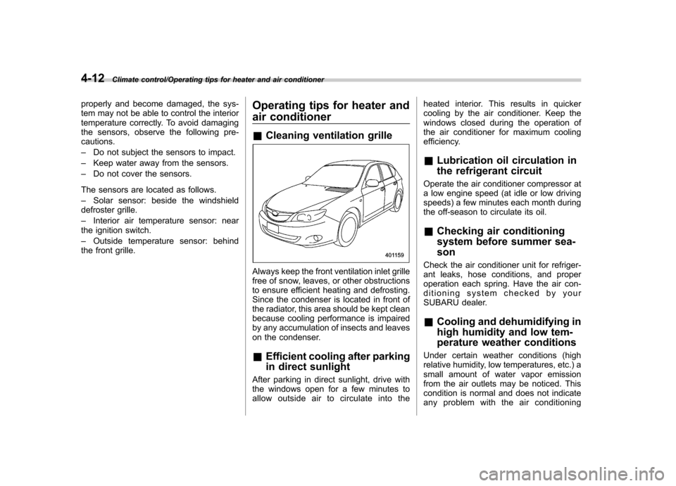
Cleaning ventilation grille
Always keep the front ventilation inlet grille
free of snow, leaves, or other obstructions
to ensure efficient heating and defrosting.
Since the condenser is located in front of
the radiator, this area should be kept clean
because cooling performance is impaired
by any accumulation of insects and leaves
on the condenser. &Efficient cooling after parking
in direct sunlight
After parking in direct sunlight, drive with
the windows open for a few minutes to
allow outside air to circulate into the heated interior. This results in quicker
cooling by the air conditioner. Keep the
windows closed during the operation of
the air conditioner for maximum cooling
efficiency. &
Lubrication oil circulation in
the refrigerant circuit
Operate the air conditioner compressor at
a low engine speed (at idle or low driving
speeds) a few minutes each month during
the off-season to circulate its oil. & Checking air conditioning
system before summer sea-son
Check the air conditioner unit for refriger-
ant leaks, hose conditions, and proper
operation each spring. Have the air con-
ditioning system checked by your
SUBARU dealer. & Cooling and dehumidifying in
high humidity and low tem-
perature weather conditions
Under certain weather conditions (high
relative humidity, low temperatures, etc.) a
small amount of water vapor emission
from the air outlets may be noticed. This
condition is normal and does not indicate
any problem with the air conditioning
Page 254 of 414

an additional four times. If the vehicle fails
to start after the additional attempts, the
remote engine start system will abort and
return to a non-activated state. &Remote start safety features
For safety and security reasons, the
system will fail to start and beep the horn
twice or shut down the engine during
remote start operation if any of the
following conditions occur. . The brake pedal is depressed before
the vehicle ignition switch is turned “on ”.
. The key was already in the ignition
switch.. The engine hood is opened.
. The vehicle ’s engine idle speed has
reached a level over 3,000 rpm.. The alarm is triggered by opening a
door or the rear gate.
NOTE . The security indicator light on the
combination meter will stop flashing
while under remote engine start opera-
tion, but the vehicle is still protected.. If the vehicle is entered during
remote engine start operation, the
system will not record entry in the
alarm history. &
Entering the vehicle while it
is running via remote start
1. Unlock the vehicle doors using the
remote keyless entry system. If the vehi-cle ’s doors are unlocked manually using
the key, the vehicle ’s alarm system will
trigger and the remote engine start system
will turn off. Inserting the key into the
ignition switch and turning it to the “ON ”
position or pressing the unlock button “
”
on the remote keyless entry transmitter
will disarm the alarm system. Refer to“ Alarm system ”F 2-15.
2. Enter the vehicle. Do not depress the
brake pedal.
3. Insert the key into the ignition switch
and turn to the “ON ”position. If the ignition
switch is accidentally turned to the“ START ”position, the system ’s “starter
anti-grind ”feature will prevent the starter
from re-cranking.
4. Depress the brake pedal. The remote
starter disengages, the vehicle ’s power
window features are re-enabled and the
vehicle will operate normally.
& Entering the vehicle follow-
ing remote engine start shut-down
An alarm trigger may occur if the vehicle is
opened by the remote keyless entry transmitter within a few seconds immedi-
ately following remote engine start shut-down. &
Pre-heating or pre-cooling
the interior of the vehicle
Before exiting the vehicle, set the tem-
perature controls to the desired setting
and operation. After the system starts the
vehicle, the heater or air-conditioning will
activate and heat or cool the interior to
your setting. & Service mode
In service mode, the remote start function
is temporarily disabled to prevent the
system from unexpectedly starting the
engine while being serviced. ! To engage the service mode
Turntheignitionswitchtothe “ON ”
position, depress and hold the brake
pedal, then press and release the “
”
button on the remote engine start trans-
mitter three times. The system will pause
for 1 second and then flash the turn signal
lights and honk the horn three times
indicating that the system is in service
mode. When attempting to activate the
remote start system while in service
mode, the turn signal lights will flash and
the horn will honk two times and will not
Starting and operating/Remote engine start system (dealer option)7-11
– CONTINUED –
Page 390 of 414

crease in temperature could cause
tread separation, and failure of the
tire(s). Possible resulting loss of
vehicle control could lead to anaccident. !Measuring and adjusting air
pressure to achieve proper in-
flation
Check and, if necessary, adjust the
pressure of each tire (including the
spare) at least once a month and
before any long journey. Check the
tire pressures when the tires are
cold. Use a pressure gauge to
adjust the tire pressures to the
specific values. Driving even a
short distance warms up the tires
and increases the tire pressures.
Also, the tire pressures are affected
by the outside temperature. It is
best to check tire pressure out-
doors before driving the vehicle.
When a tire becomes warm, the air
inside it expands, causing the tire
pressure to increase. Be careful not
to mistakenly release air from a
warm tire to reduce its pressure. &
Glossary of tire terminology
. Accessory weight
The combined weight (in excess of
those standard items which may be
replaced) of automatic transmis-
sion, power steering, power brakes,
power windows, power seats, radio,
and heater, to the extent that these
items are available as factory-in-
stalled equipment (whether in-
stalled or not). . Bead
The part of the tire that is made of
steel wires, wrapped or reinforced
by ply cords and that is shaped to fit
the rim.. Bead separation
A breakdown of the bond between
components in the bead.. Bias ply tire
A pneumatic tire in which the ply
cords that extend to the beads are
laid at alternate angles substantially
less than 90 degrees to the center-
line of the tread. . Carcass
The tire structure, except tread and sidewall rubber which, when in-
flated, bears the load. .
Chunking
The breaking away of pieces of the
tread or sidewall.. Cold tire pressure
The pressure in a tire that has been
driven less than 1 mile or has been
standing for three hours or more.. Cord
The strands forming the plies in the tire. . Cord separation
The parting of cords from adjacent
rubber compounds.. Cracking
Any parting within the tread, side-
wall, or inner liner of the tire
extending to cord material. . Curb weight
The weight of a motor vehicle with
standard equipment including the
maximum capacity of fuel, oil and
coolant, and if so equipped, air
conditioning and additional weight
optional engine.
Consumer information and Reporting safety defects/Tire information13-5
– CONTINUED –