2014 SKODA ROOMSTER brake
[x] Cancel search: brakePage 170 of 204

WARNING (Continued)■If the wheel bolts are tightened to a too low tightening torque, the rim
can come loose when the car is moving. A tightening torque which is too
high can damage the bolts and threads and this can result in permanent
deformation of the contact surfaces on the rim.■
In case of incorrect treatment of the wheel bolts, the wheel can loosen
when the car is moving.
Note
The national legal requirements must be observed when changing a wheel.
Preliminary work
Read and observe
on page 166 first.
Before changing the wheel, the following work must be carried out.
›
Have all the occupants get out. The passengers should not stand on the
road (instead they should remain behind a crash barrier, for instance) while
the wheel is being changed.
›
Switch off the engine.
›
Engage the 1st gear or place the selector lever of the automatic transmission
in the P-position .
›
Apply the handbrake firmly.
›
Uncouple a trailer.
›
Remove the vehicle tool kit » page 166 and the spare wheel » page 159 ,
Spare and temporary spare wheel from the boot.
Changing a wheel
Read and observe
on page 166 first.
When changing a wheel, the following instructions must be followed.
›
Remove the full wheel trim or the caps of the wheel bolts.
›
First of all slacken the anti-theft wheel bolt and then the other wheel bolts.
›
Jack up the vehicle until the wheel that needs changing is clear of the
ground.
›
Unscrew the wheel bolts and place them on a clean surface (cloth, paper, etc.).
›
Remove the wheel carefully.
›
Attach the spare wheel and slightly screw on the wheel bolts.
›
Lower the vehicle.
› Tighten the opposite wheel bolts alternately (cross-wise) with the wheel
wrench. Tighten the anti-theft wheel bolt last.›
Replace the wheel trim or the caps.
WARNING■ If it is established when changing a wheel that the wheel bolts are corro-
ded and difficult to move, then these must be replaced.■
When fitting unidirectional tyres, ensure that the direction of rotation is
correct » page 156 .
Follow-up work
Read and observe
on page 166 first.
After changing the wheel, the following work must be carried out.
›
Stow and attach the replaced wheel in the spare wheel well using a special
screw » page 159 , Spare and temporary spare wheel .
›
Stow the tool kit in the space provided and secure using the strap.
›
Check the tyre pressure on the installed spare wheel as soon as possible.
›
Have the tightening torque of the wheel bolts checked with a torque
wrench as soon as possible.
After changing the wheel, the tyre pressure should be adjusted. In vehicles
with tyre pressure monitoring, tyre pressure values are to be stor-
ed » page 125 .
Replace the damaged wheel or consult a specialist garage about repair op-
tions.
WARNINGDrive cautiously and only at a moderate speed until the tightening torque
has been checked.167Emergency equipment and self-help
Page 174 of 204

Preparations for using the breakdown kitRead and observe
on page 170 first.
The following preparatory work must be carried out before using the puncture
repair kit.
›
Have all the occupants get out. The passengers should not stand on the
road (instead they should remain behind a crash barrier, for instance) while
the wheel is being changed.
›
Switch off the engine.
›
Engage the 1st gear or place the selector lever of the automatic transmission
in the P-position .
›
Apply the handbrake firmly.
›
Check that you can carry out the repairs with the breakdown kit » page 169.
›
Uncouple a trailer.
›
Remove the
breakdown kit from the boot.
›
Stick the appropriate sticker
2
» Fig. 152 on page 170 onto the dashboard in
the driver's field of view.
›
Unscrew the valve cap.
›
Use the valve remover
1
to unscrew the valve core and place it on a clean
surface (rag, paper, etc.).
Sealing and inflating the tyre
Read and observe
on page 170 first.
Sealing
›
Shake the tyre inflator bottle
10
» Fig. 152 on page 170 vigorously several
times.
›
Firmly screw the inflation hose
3
onto the tyre inflator bottle
10
in a clock-
wise direction. The film on the cap is pierced automatically.
›
Remove the plug from the inflation hose
3
and plug the open end fully onto
the tyre valve.
›
Hold the bottle
10
with the bottom facing upwards and fill all of the sealing
agent from the tyre inflator bottle into the tyre.
›
Remove the empty tyre inflator bottle from the valve.
›
Screw the valve core back into the tyre valve using the valve remover
1
.
Inflating
›
Screw the air compressor tyre inflation hose
5
» Fig. 152 on page 170 firmly
onto the tyre valve.
›
Check that the air release valve
7
is closed.
› Start the engine and run it in idle.›Plug the connector 9 into 12 Volt socket
» page 82, 12-volt power outlet .›
Switch on the air compressor with the ON and OFF switch
8
.
›
Allow the air compressor to run until a pressure of 2.0 - 2.5 bar is achieved.
Maximum run time of 8 minutes » .
›
Switch off the air compressor.
›
If you cannot reach an air pressure of 2.0 – 2.5 bar, unscrew the tyre inflation
hose
5
from the tyre valve.
›
Drive the vehicle 10 metres forwards or backwards to allow the sealing agent
to “distribute” in the tyre.
›
Firmly screw the tyre inflation hose
5
back onto the tyre valve and repeat
the inflation process.
›
If you cannot reach the required tyre inflation pressure here either, this
means the tyre has sustained too much damage. You cannot seal with tyre with the breakdown kit »
.
›
Switch off the air compressor.
›
Remove the tyre inflation hose
5
from the tyre valve.
Once a tyre pressure of 2.0 – 2.5 bar is reached, the journey may be continued
at a maximum speed of 80 km/h (50 mph).
WARNING■ If you cannot inflate the tyre to at least 2.0 bar, this means the damage
sustained was too serious. The sealing agent cannot be used to seal the
tyre.
Do not drive the vehicle any further! Seek help from a specialist ga-
rage.■
The tyre inflation hose and air compressor may get hot as the tyre is be-
ing inflated – there is a risk of burning.
CAUTION
Switch off the air compressor after running 8 minutes at the latest – there is a
risk of overheating. Allow the air compressor to cool a few minutes before
switching it on again.
Notes for driving with tyre repaired
Read and observe
on page 170 first.
The inflation pressure of the repaired tyre must be checked after driving for 10
minutes.
171Emergency equipment and self-help
Page 176 of 204

WARNING■Do not clamp the jump-start cable to the negative terminal of the dis-
charged battery. There is the risk of detonating gas seeping out the battery
being ignited by the strong spark which results from the engine being star-
ted.■
The non-insulated parts of the terminal clamps must never touch each
other – there is a risk of short circuit.
■
The jump-start cable connected to the positive terminal of the battery
must not come into contact with electrically conducting parts of the vehicle
– there is a risk of short circuit.
■
Route the jump-start cables so that they cannot be caught by any rotat-
ing parts in the engine compartment.
■
There must not be any contact between the two vehicles otherwise cur-
rent may flow as soon as the negative terminals are connected.
Jump-starting in vehicles with the START-STOP system
Fig. 154
Engine earth: START-STOP sys-
tem
Read and observe on page 172 first.
The jump-start cable must only be connected to the engine earthing point on
vehicles with the START-STOP system » Fig. 154.
Towing the vehicle
Introduction
This chapter contains information on the following subjects:
Front towing eye
174
Rear towing eye
174
Vehicles with a tow hitch
174The following guidelines must be observed when towing.
Vehicles with manual transmission may be towed in with a tow bar or a tow
rope or with the front or rear wheels raised.
Vehicles with automatic transmission may be towed in with a tow bar or a tow
rope or with the front wheels raised. If the vehicle is raised at rear, the auto-
matic gearbox is damaged!
Driver of the tow vehicle›
Engage the clutch gently when starting off or depress the accelerator partic-
ularly gently if the vehicle is fitted with an automatic gearbox.
›
Only then, approach correctly when the rope is taut.
The maximum towing speed is 50 km/h.
Driver of the towed vehicle
›
Switch on the ignition so that the steering wheel is not locked and so that
the turn signal lights, windscreen wipers and windscreen washer system can
be used.
›
Take the vehicle out of gear or move the selector lever into position N if the
vehicle is fitted with an automatic gearbox.
Please note that the brake servo unit and power steering only operate if the
engine is running. If the engine is not running, significantly more physical force
is required to depress the brake pedal and steer the vehicle.
If using a tow rope, ensure that it is always kept taught.
Both drivers should be familiar with the problems which might possibly occur while a vehicle is being towed. Unskilled drivers should not attempt to tow in
another vehicle or to be towed in.
The vehicle must be transported on a special breakdown vehicle or trailer if it
is not possible to tow in the vehicle in the way described or if the towing dis-
tance is greater than 50 km.
WARNING■ When towing, respect the national legal provisions, especially those
which relate to the identification of the towing vehicle and the vehicle be-
ing towed.■
When towing, exercise increased caution.
■
The tow rope must not be twisted, as this may in certain circumstances
result in the front towing eye being unscrewed on your vehicle.
■
Do not use a one-sided twisted tow rope, because the towing eye could
become unscrewed on the vehicle.
173Emergency equipment and self-help
Page 179 of 204

Note■We recommend always carrying replacement fuses in the vehicle. A box of
replacement fuses can be purchased from ŠKODA Original Accessories.■
There can be multiple power consuming devices for one fuse.
■
A single consumer may use several fuses.
Fuses in the dash panel
Fig. 157
Underside of the dash panel: Dis-
tribution board cover.
Fig. 158
Schematic representation of the fuse box for vehicles with left-
hand steering/right-hand steering
Read and observe
and on page 175 first.
The fuses are located on the left side of the dash panel behind a cover.
› Carefully remove the cover in the direction of the arrow
» Fig. 157.
› After the fuse has been replaced, replace the cover in the dash panel in the
opposite direction of the arrow so that the guide lugs are guided into the
openings of the dash panel. Close the cover until it clicks into place.
Fuse assignment in the dash panelNo.Consumer1S-contact2START-STOP, air-conditioning system3Instrument cluster, headlamp beam adjustment4Control unit for ABS, button for START STOP5Petrol engine: Speed regulating system6Reversing light (manual gearbox)7Ignition, engine control unit, automatic gearbox8Brake pedal switch, clutch pedal switch9Operating controls for the heating, control unit for air conditioning
system, parking aid, control unit for cornering lights, radiator fan,
washing nozzles10Windscreen Wiper and Washer System11Mirror adjustment12Control unit for trailer detection13Control unit for automatic gearbox14Motor for halogen projector headlights with cornering light function15PDA navigation system16Electro-hydraulic power steering17Light switch power supply18Mirror heater19S-contact20Alarm21Reversing light, fog lights with the function CORNER
22
Operating controls for the heating, control unit for air conditioning
system, parking aid, mobile phone, instrument cluster, steering an-
gle sender, ESC, vehicle voltage control unit, multifunction steering
wheel23Interior lighting, storage compartment and luggage compartment,
side lights24Central control unit25Seat heaters26Rear window wiper 176Do-it-yourself
Page 180 of 204

No.Consumer27Telephone preinstallation28Petrol engine: AKF valve, Diesel engine: Control flap29Injection, coolant pump30Fuel pump, ignition, Cruise control system, operation of PTC relay31Lambda probe32High pressure fuel pump, pressure valve33Engine control unit34Engine control unit, vacuum pump35Daytime running lights/radio for vehicles with START-STOP36Main beam37Rear fog light, DC/DC converter START-STOP38Fog lights39Air blower for heating40-41Not assigned42Rear window heater43Horn44Windscreen wipers45Central control unit for convenience system46Engine control unit, fuel pump47Cigarette lighter, power socket in the luggage compartment48ABS, START-STOP (DC/DC) converter, ESC49Turn signal lights, brake lights50START-STOP (DC/DC) transformer, radio51Electrical power window (front and rear) - left side52Electrical power window (front and rear) - right side53Parking light = left side, electrical sliding/tilting roof54START-STOP (instrument cluster), alarm55Control unit for automatic gearbox56Headlight cleaning system, parking light - right side57Left low beam, headlight range adjustment58Low beam on the rightFuses in the engine compartmentFig. 159
Vehicle battery: Distribution board cover.
Fig. 160
Schematic representation of fuse
box in engine compartment
Read and observe and on page 175 first.
› Press the securing clips on the fuse box cover together at the same time in
the direction of arrow
A
» Fig. 159 and remove the cover in the direction of
arrow
B
.
› Release the fixtures in the openings
C
using a flat screwdriver and fold the
cover upwards in direction of arrow
D
.
Fuse assignment in engine compartment
No.Consumer1Generator2Not assigned3Interior4Electrical auxiliary heating system5Interior 177Fuses and light bulbs
Page 185 of 204

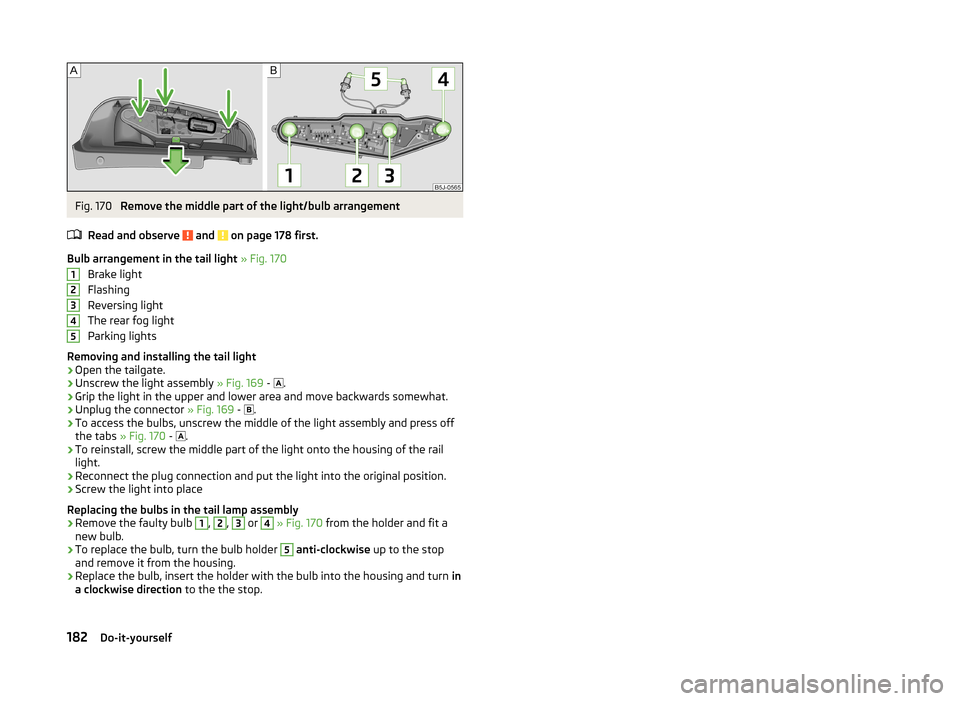
Fig. 170
Remove the middle part of the light/bulb arrangement
Read and observe
and on page 178 first.
Bulb arrangement in the tail light » Fig. 170
Brake light
Flashing
Reversing light
The rear fog light
Parking lights
Removing and installing the tail light
›
Open the tailgate.
›
Unscrew the light assembly » Fig. 169 -
.
›
Grip the light in the upper and lower area and move backwards somewhat.
›
Unplug the connector
» Fig. 169 -
.
›
To access the bulbs, unscrew the middle of the light assembly and press off
the tabs » Fig. 170 -
.
›
To reinstall, screw the middle part of the light onto the housing of the rail
light.
›
Reconnect the plug connection and put the light into the original position.
›
Screw the light into place
Replacing the bulbs in the tail lamp assembly
›
Remove the faulty bulb
1
,
2
,
3
or
4
» Fig. 170 from the holder and fit a
new bulb.
›
To replace the bulb, turn the bulb holder
5
anti-clockwise up to the stop
and remove it from the housing.
›
Replace the bulb, insert the holder with the bulb into the housing and turn in
a clockwise direction to the the stop.
12345182Do-it-yourself
Page 189 of 204

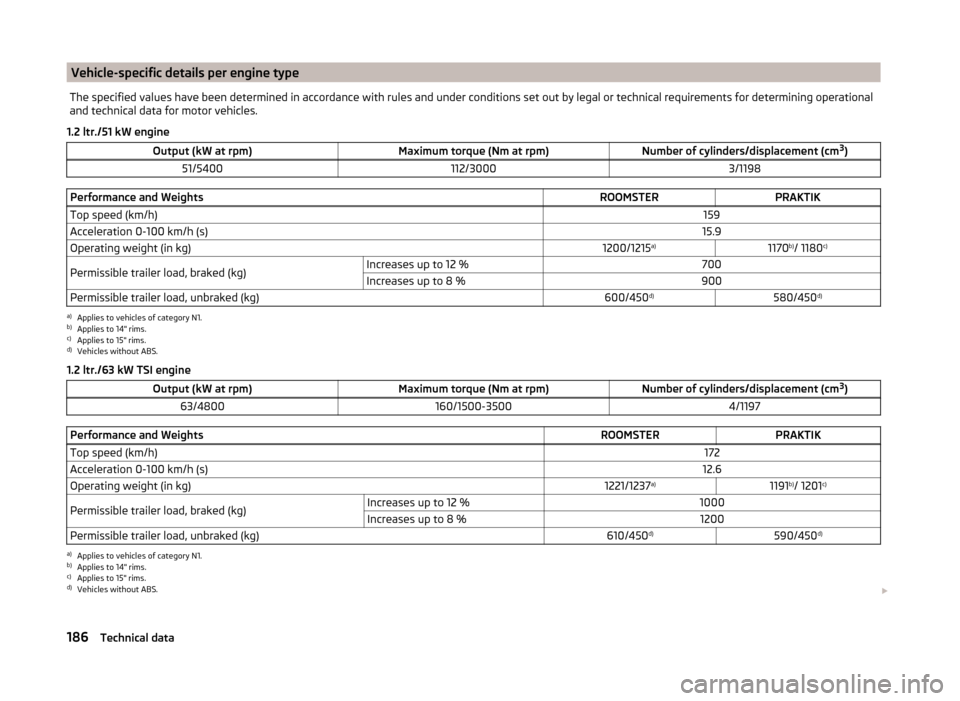
Vehicle-specific details per engine typeThe specified values have been determined in accordance with rules and under conditions set out by legal or technical requirements for determining operational
and technical data for motor vehicles.
1.2 ltr./51 kW engine
Output (kW at rpm)Maximum torque (Nm at rpm)Number of cylinders/displacement (cm 3
)51/5400112/30003/1198Performance and WeightsROOMSTERPRAKTIKTop speed (km/h)159Acceleration 0-100 km/h (s)15.9Operating weight (in kg)1200/1215 a)1170b)
/ 1180 c)Permissible trailer load, braked (kg)Increases up to 12 %700Increases up to 8 %900Permissible trailer load, unbraked (kg)600/450 d)580/450d)a)
Applies to vehicles of category N1.
b)
Applies to 14" rims.
c)
Applies to 15" rims.
d)
Vehicles without ABS.
1.2 ltr./63 kW TSI engine
Output (kW at rpm)Maximum torque (Nm at rpm)Number of cylinders/displacement (cm 3
)63/4800160/1500-35004/1197Performance and WeightsROOMSTERPRAKTIKTop speed (km/h)172Acceleration 0-100 km/h (s)12.6Operating weight (in kg)1221/1237 a)1191b)
/ 1201 c)Permissible trailer load, braked (kg)Increases up to 12 %1000Increases up to 8 %1200Permissible trailer load, unbraked (kg)610/450 d)590/450 d)a)
Applies to vehicles of category N1.
b)
Applies to 14" rims.
c)
Applies to 15" rims.
d)
Vehicles without ABS.
186Technical data
Page 190 of 204

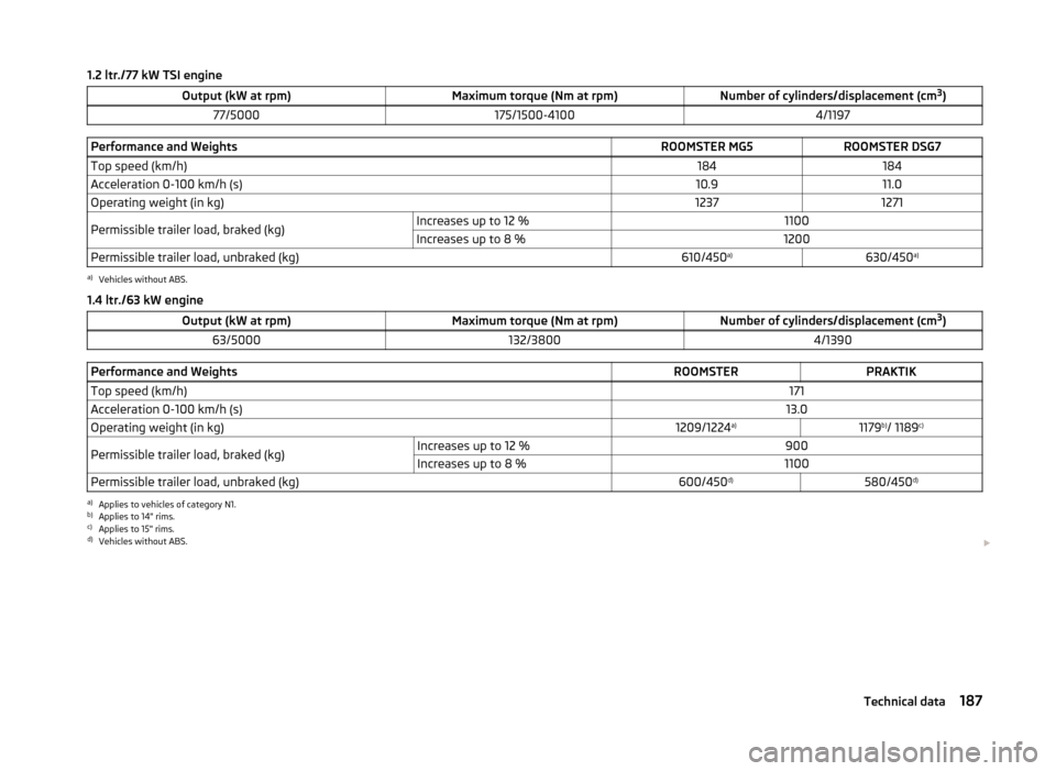
1.2 ltr./77 kW TSI engineOutput (kW at rpm)Maximum torque (Nm at rpm)Number of cylinders/displacement (cm3
)77/5000175/1500-41004/1197Performance and WeightsROOMSTER MG5ROOMSTER DSG7Top speed (km/h)184184Acceleration 0-100 km/h (s)10.911.0Operating weight (in kg)12371271Permissible trailer load, braked (kg)Increases up to 12 %1100Increases up to 8 %1200Permissible trailer load, unbraked (kg)610/450 a)630/450 a)a)
Vehicles without ABS.
1.4 ltr./63 kW engine
Output (kW at rpm)Maximum torque (Nm at rpm)Number of cylinders/displacement (cm 3
)63/5000132/38004/1390Performance and WeightsROOMSTERPRAKTIKTop speed (km/h)171Acceleration 0-100 km/h (s)13.0Operating weight (in kg)1209/1224 a)1179b)
/ 1189 c)Permissible trailer load, braked (kg)Increases up to 12 %900Increases up to 8 %1100Permissible trailer load, unbraked (kg)600/450 d)580/450d)a)
Applies to vehicles of category N1.
b)
Applies to 14" rims.
c)
Applies to 15" rims.
d)
Vehicles without ABS.
187Technical data