2014 Seat Ibiza ST engine
[x] Cancel search: enginePage 91 of 240

Opening and closing
●
Closing the windows without observing and
ensuring it is clear could cause serious injury
to you and third parties. Make sure that no
one is in the path of a window.
● Never allow people to remain in the vehicle
when you close the vehicle from the outside.
The windows cannot be opened even in an
emergency.
● The roll-back function does not prevent fin-
gers or other parts of the body getting
pinched against the window frame. Risk of
accident. Convenience opening and closing*
Using the door lock*
– Hold the key in the door lock of the driver
door in either the locking or the unlocking
position until all windows are either
opened or closed.
– Release the key to interrupt this function.
Using the remote control
– Keep the locking/unlocking button pressed
for the electric window risers to
open/close; if you stop pressing the but-
ton, the window raising/lowering function
is stopped.
– If the automatic raising is stopped and im-
mediately after, the opening button is kept
pressed, the window risers will lower. –
Once the windows are completely closed,
the turn signals will flash.
Panoramic tilting sunroof* Opening or closing of the
panoramic/tilting sunroof Read the additional information carefully
››› page 10
The panoramic/tilting sunroof is opened and
closed by using the switch when the ignition
is switched on.
Always close the panoramic/tilting sunroof
fully if you park the vehicle or leave it unat-
tended ››› .
The tilting sunroof can be operated for up to
about ten minutes after the ignition has been
switched off, provided the driver door and
the front passenger door are not opened.
Sun visor
The sun visor is opened and closed manually
(independently of the panoramic/tilting sun-
roof). WARNING
● Incorrect use of the tilting sunroof can re-
sult in injury. ●
Never close the tilting sunroof without first
checking that there are no obstructions. Risk
of serious injury to you or others. Make sure
that no one is in the path of the tilting sun-
roof.
● Always take the vehicle key with you when
you leave the vehicle.
● Never leave children or disabled persons in
the vehicle, particularly if they have access to
the keys. Unsupervised use of a key could
mean that the engine is started or that elec-
trical equipment is used (e.g. electric tilting
sunroof) with a risk of accident. The doors
can be locked using the remote control key.
This could become an obstacle for assistance
in an emergency situation.
● The tilting sunroof continues to function
until one of the front doors is opened and the
key removed from the ignition.
● Ensure that no object and/or end is be-
tween the glass and the sunroof when the
one-touch opening/closing function is reset. Convenience closing*
Using the door lock
– Hold the key in the door lock of the driver
door in the locking position until the tilting
sunroof is closed.
– Release the key to interrupt this function.
»
89Technical specifications
Advice
Operation
Safety
The essentials
Page 98 of 240

Operation
Interior lights Front interior light Read the additional information carefully
››› page 15 Note
If not all the vehicle doors are closed, the in-
terior lights will be switched off after approx.
10 minutes, providing the ignition key has
been removed and the courtesy light position
selected. This prevents the battery from dis-
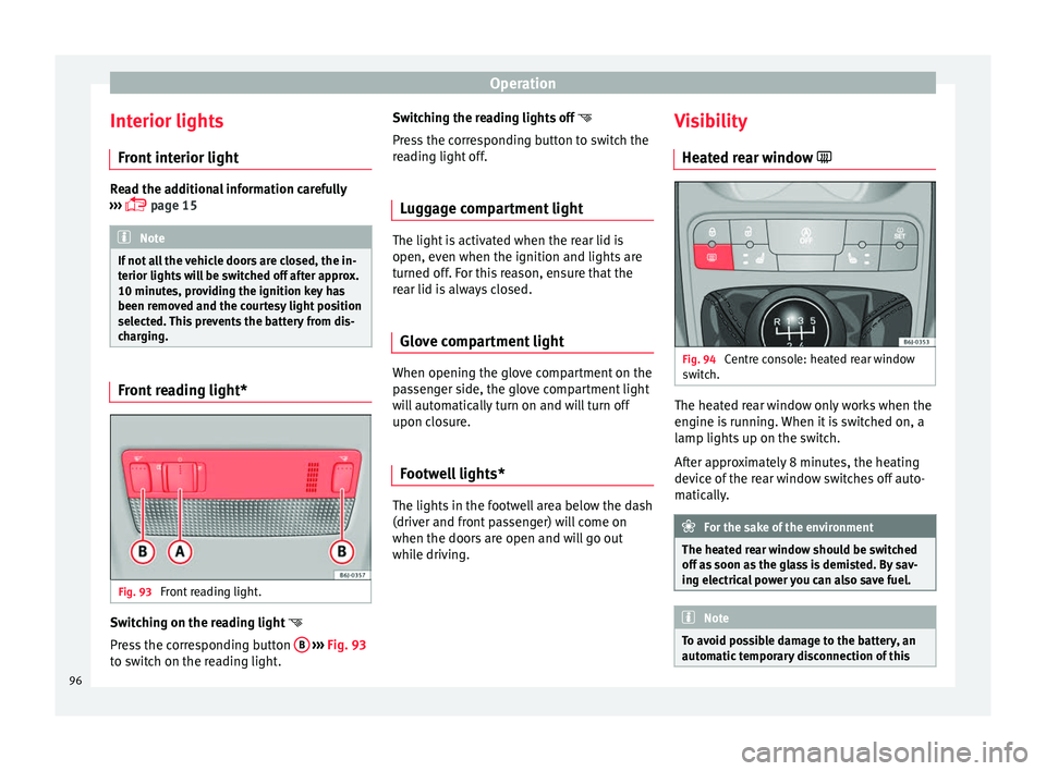
charging. Front reading light*
Fig. 93
Front reading light. Switching on the reading light
Press the corresponding button B
››› Fig. 93
to switch on the reading light. Switching the reading lights off
Press the corresponding button to switch the
reading light off.
Luggage compartment light The light is activated when the rear lid is
open, even when the ignition and lights are
turned off. For this reason, ensure that the
rear lid is always closed.
Glove compartment light When opening the glove compartment on the
passenger side, the glove compartment light
will automatically turn on and will turn off
upon closure.
Footwell lights* The lights in the footwell area below the dash
(driver and front passenger) will come on
when the doors are open and will go out
while driving.Visibility
Heated rear window Fig. 94
Centre console: heated rear window
switch. The heated rear window only works when the
engine is running. When it is switched on, a
lamp lights up on the switch.
After approximately 8 minutes, the heating
device of the rear window switches off auto-
matically.
For the sake of the environment
The heated rear window should be switched
off as soon as the glass is demisted. By sav-
ing electrical power you can also save fuel. Note
To avoid possible damage to the battery, an
automatic temporary disconnection of this 96
Page 104 of 240

Operation
WARNING
● Never drive if the head restraints have been
removed. Risk of injury.
● Never drive if the head restraints are in an
unsuitable position, there is a risk of serious
injury.
● After refitting the head restraint, you must
always adjust it properly for height to achieve
optimal protection.
● Please observe the safety warnings in ››› in Correct adjustment of front head restraints
on page 33.
Note
● To fit and remove the rear head restraints,
gently tilt the seat backrest forwards.
● When fitting the head restraints again, in-
sert the tubes as far as possible into the
guides without pressing the button. Seat functions
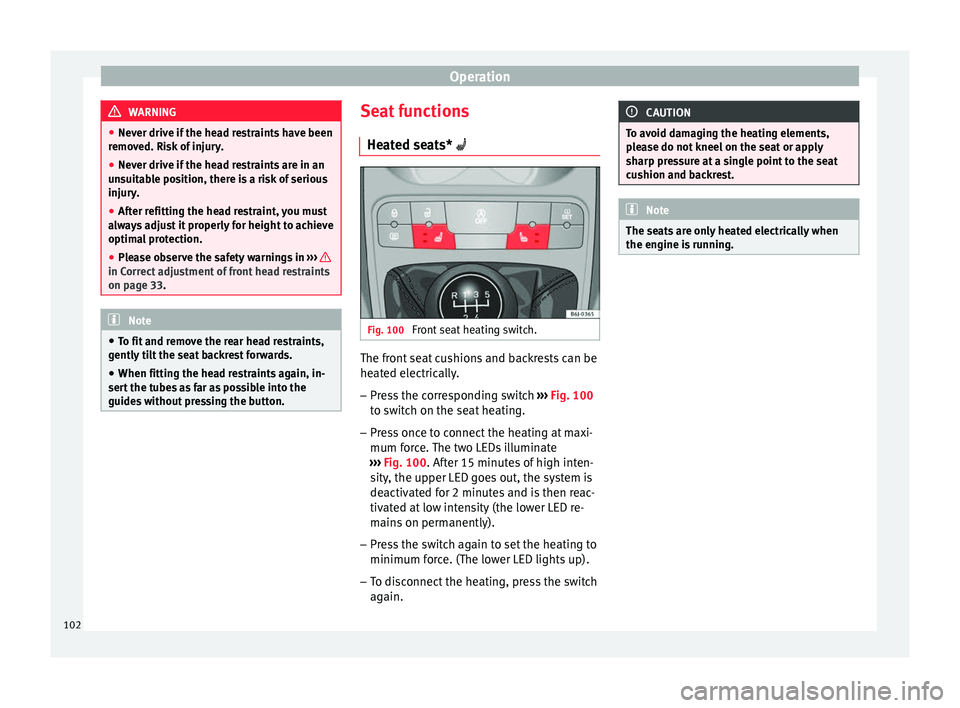
Heated seats* Fig. 100
Front seat heating switch. The front seat cushions and backrests can be
heated electrically.
– Press the corresponding switch ››› Fig. 100
to switch on the seat heating.
– Press once to connect the heating at maxi-
mum force. The two LEDs illuminate
››› Fig. 100 . After 15 minutes of high inten-
s ity
, the upper LED goes out, the system is
deactivated for 2 minutes and is then reac-
tivated at low intensity (the lower LED re-
mains on permanently).
– Press the switch again to set the heating to
minimum force. (The lower LED lights up).
– To disconnect the heating, press the switch
again. CAUTION
To avoid damaging the heating elements,
please do not kneel on the seat or apply
sharp pressure at a single point to the seat
cushion and backrest. Note
The seats are only heated electrically when
the engine is running. 102
Page 109 of 240

Transport and practical equipment
Cigarette lighter* Fig. 113
Lighter. –
Press on the cigarette lighter ››› Fig. 113 to
activ at
e it ››› .
– Wait for the lighter to spring out.
– Pull out the cigarette lighter and light the
cigarette on the glowing coil. WARNING
● Improper use of the cigarette lighter can
lead to serious injuries or start a fire.
● Using the lighter carefully. Carelessness or
negligence when using the cigarette lighter
can cause burns and serious injuries.
● The lighter only works when the ignition is
turned on or the engine is running. To avoid
the risk of fire, never leave children alone in-
side the vehicle. Power socket
Fig. 114
Front power socket. The 12 Volt cigarette lighter power socket can
also be used for other electrical components
with a power rating of up to 120 Watt. When
the engine is switched off, however, the vehi-
cle battery will discharge. For further informa-
tion see
››› page 155 . WARNING
The power sockets and the connected acces-
sories will only operate when the ignition is
on or when the engine is running. Improper
use of the sockets or electrical accessories
can lead to serious injuries or cause a fire. To
avoid the risk of injury, never leave children
alone inside the vehicle. Note
● The use of electrical appliances with the
engine switched off will cause a battery dis-
charge.
● Before using any electrical accessories, see
the instructions in ››› page 155. Power socket in the luggage
compartment*
3 Applies to the model: IBIZA ST
Fig. 115
Detailed view of the side trim in the
luggage compartment: 12 volt socket –
Lift the power socket cover ››› Fig. 115 .
– Inser
t the plug of the electrical appliance
into the power socket.
Electrical equipment can be connected to any
of the 12 volt sockets. The appliances con-
nected to the power socket must not exceed
a power rating of 100 W. »
107
Technical specifications
Advice
Operation
Safety
The essentials
Page 110 of 240

Operation
CAUTION
Always use the correct type of plugs to avoid
damaging the sockets. Note
● The power sockets will only work with the
ignition on.
● The use of electrical appliances with the
engine switched off will cause a battery dis-
charge. Auxiliary audio connection (AUX)*
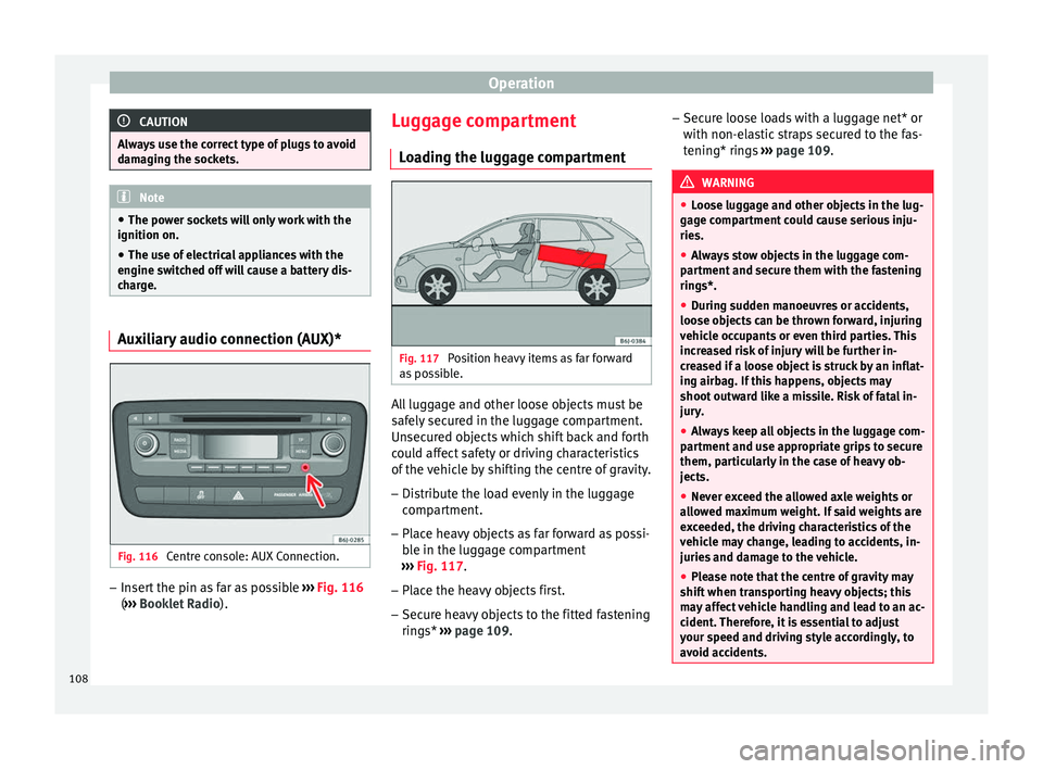
Fig. 116
Centre console: AUX Connection. –
Insert the pin as far as possible ››› Fig. 116
( ››› Booklet Radio ). L
ug gage compartment
Loading the luggage compartment Fig. 117
Position heavy items as far forward
as possible. All luggage and other loose objects must be
safely secured in the luggage compartment.
Unsecured objects which shift back and forth
could affect safety or driving characteristics
of the vehicle by shifting the centre of gravity.
– Distribute the load evenly in the luggage
compartment.
– Place heavy objects as far forward as possi-
ble in the luggage compartment
››› Fig. 117 .
– Plac
e the heavy objects first.
– Secure heavy objects to the fitted fastening
rings* ››› page 109. –
Secur
e loose loads with a luggage net* or
with non-elastic straps secured to the fas-
tening* rings ››› page 109. WARNING
● Loose luggage and other objects in the lug-
gage compartment could cause serious inju-
ries.
● Always stow objects in the luggage com-
partment and secure them with the fastening
rings*.
● During sudden manoeuvres or accidents,
loose objects can be thrown forward, injuring
vehicle occupants or even third parties. This
increased risk of injury will be further in-
creased if a loose object is struck by an inflat-
ing airbag. If this happens, objects may
shoot outward like a missile. Risk of fatal in-
jury.
● Always keep all objects in the luggage com-
partment and use appropriate grips to secure
them, particularly in the case of heavy ob-
jects.
● Never exceed the allowed axle weights or
allowed maximum weight. If said weights are
exceeded, the driving characteristics of the
vehicle may change, leading to accidents, in-
juries and damage to the vehicle.
● Please note that the centre of gravity may
shift when transporting heavy objects; this
may affect vehicle handling and lead to an ac-
cident. Therefore, it is essential to adjust
your speed and driving style accordingly, to
avoid accidents. 108
Page 116 of 240

Operation
Technical Service should be consulted to
check the system.
● To ensure correct operation, the grilles on
both sides of the screen must not be obstruc-
ted ●
When the engine is under extreme strain,
switch off the compressor for a moment. Heating
Controls Fig. 125
Heating controls on the dash panel. –
Using the controls A and
C and with the
switch B
››› Fig. 125 you can adjust the
t emper
ature, the air distribution and the
blower speed.
– Press the D button to switch air recircula-
tion mode on or off. When the function is activated, a warning light on the button is
turned on.
Temperature
Switch A adjusts temperature. The desired
temperature inside the vehicle cannot be
lower than the ambient temperature. Maxi-
mum heat output, which is needed to defrost the windows quickly, is only available when
the engine has reached its operating temper-
ature.
114
Page 119 of 240

Air conditioning
Heating
Maximum heat output, which is needed to
defrost the windows quickly, is only available
when the engine has reached its operating
temperature. Note
Remember that the temperature of the engine
coolant should be optimum to ensure that the heating system functions correctly (except in
vehicles fitted with additional heating*).
Air outlets
Fig. 127
Air vents Air distribution
CSymbolMain air output through out-
lets
1, 2
5
1, 2, 5
3, 4 Outlets
3 and
4 can be closed or opened
separately using the slats and the air flow di-
rected as required.
117
Technical specifications
Advice
Operation
Safety
The essentials
Page 120 of 240

Operation
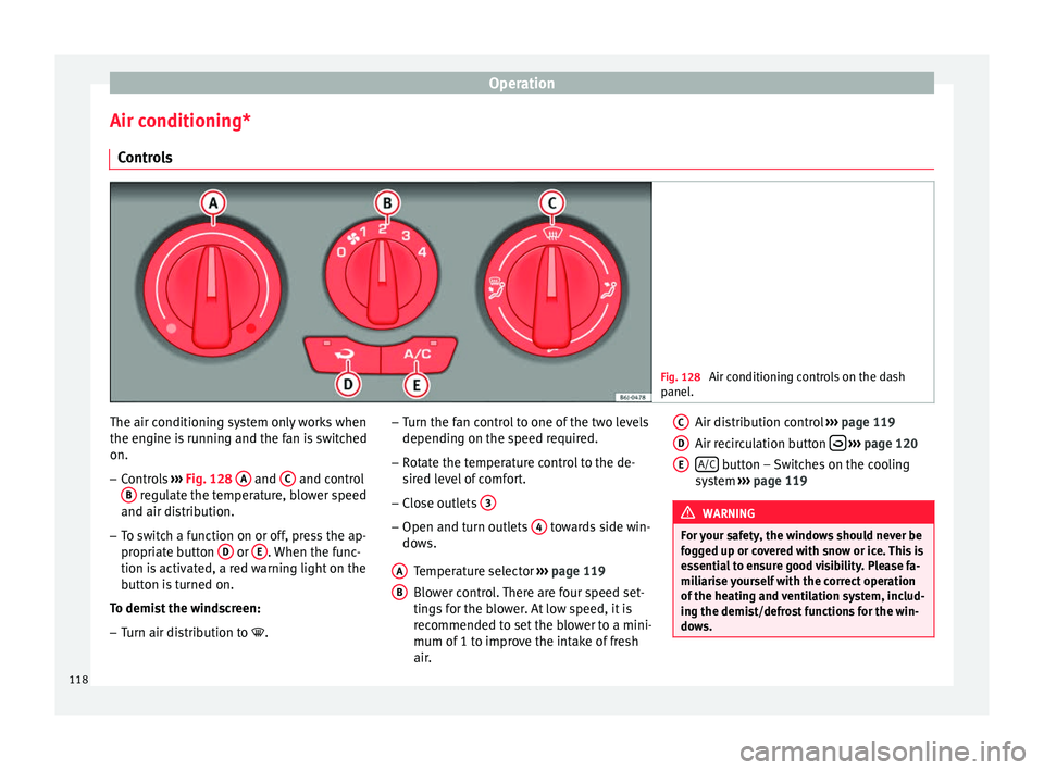
Air conditioning* Controls Fig. 128
Air conditioning controls on the dash
panel. The air conditioning system only works when
the engine is running and the fan is switched
on.
–
Controls ››› Fig. 128 A and
C and control
B regulate the temperature, blower speed
and air distribution.
– To switch a function on or off, press the ap-
propriate button D or
E . When the func-
tion is activated, a red warning light on the
button is turned on.
To demist the windscreen: – Turn air distribution to .–
Turn the fan control to one of the two levels
depending on the speed required.
– Rotate the temperature control to the de-
sired level of comfort.
– Close outlets 3 –
Open and turn outlets 4 towards side win-
dows.
Temperature selector ››› page 119
Blower control. There are four speed set-
tings for the blower. At low speed, it is
recommended to set the blower to a mini-
mum of 1 to improve the intake of fresh
air.
A B Air distribution control
››› page 119
Air recirculation button
››› page 120
A/C button – Switches on the cooling
system ››› page 119 WARNING
For your safety, the windows should never be
fogged up or covered with snow or ice. This is
essential to ensure good visibility. Please fa-
miliarise yourself with the correct operation
of the heating and ventilation system, includ-
ing the demist/defrost functions for the win-
dows. C
D
E
118