Page 155 of 181

PETROL INJECTION
Fault finding – Interpretation of statuses17B
17B - 155V12 MR-372-J84-17B000$540.mif
SAGEM 3000
Program No.: A7
Vdiag No.: 44, 48
ET704
ET705
BRAKE SWITCH NO. 1
BRAKE SWITCH NO. 2
NOTESSpecial notes:
Only perform the tests if the statuses do not correspond with the system programming
functions.
Note:
Statuses ET704 and ET705 should change status at the same time. If they are inconsistent, consult the
interpretation of fault DF228 Brake signal.
ACTIVE
or
INACTIVEIf the brake lights are working, check the continuity and the absence of interference
resistance between the following connections:
Brake light switch, track 3 Injection computer, connector A,
black, 32-track track E4
If there is a repair method (see Technical Note 6015A, Repairing electrical wiring,
Wiring: Repair precautions), repair the wiring, otherwise replace it.
If the brake lights are not operational, check:
– the condition and fitting of the brake switch,
– the condition and conformity of the brake light fuse,
– the conformity of the values in the following table:
Continuity between
tracksInsulation between
tracks
Switch pressed
(Brake pedal released)3 and 4 1 and 2
Switch released
(brake pedal pressed)1 and 2 3 and 4
Replace the switch if the values obtained are not correct.
AFTER REPAIRDeal with any other faults. Clear the fault memory.
Switch off the ignition and carry out a road test followed by a test with the diagnostic
tool.
1JSAA741.0
Page 159 of 181

PETROL INJECTION
Fault finding – Interpretation of parameters17B
17B - 159V12 MR-372-J84-17B000$675.mif
SAGEM 3000
Program No.: A7
Vdiag No.: 44, 48
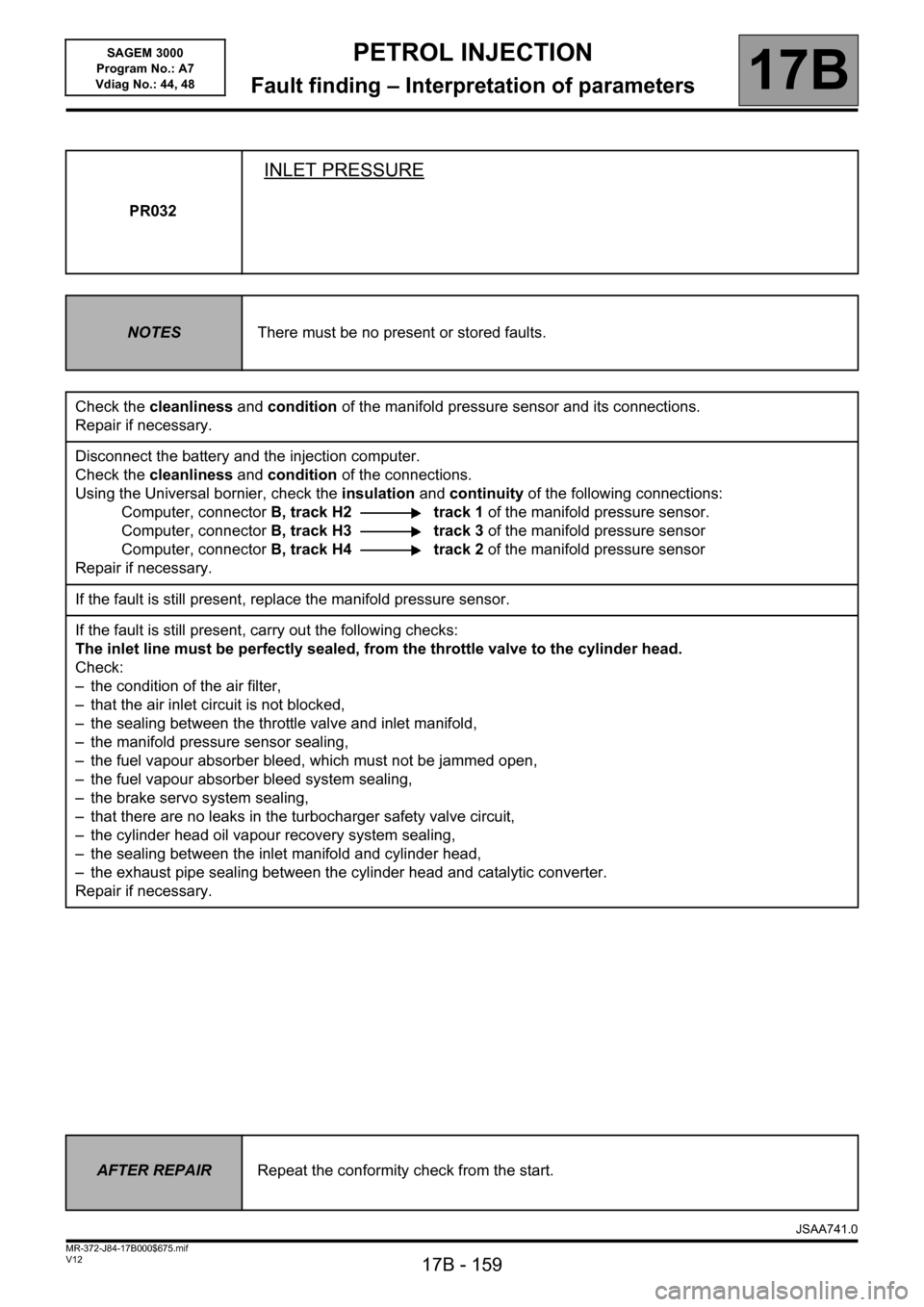
PR032
INLET PRESSURE
NOTESThere must be no present or stored faults.
Check the cleanliness and condition of the manifold pressure sensor and its connections.
Repair if necessary.
Disconnect the battery and the injection computer.
Check the cleanliness and condition of the connections.
Using the Universal bornier, check the insulation and continuity of the following connections:
Computer, connectorB, track H2 track 1 of the manifold pressure sensor.
Computer, connectorB, track H3 track 3 of the manifold pressure sensor
Computer, connectorB, track H4 track 2 of the manifold pressure sensor
Repair if necessary.
If the fault is still present, replace the manifold pressure sensor.
If the fault is still present, carry out the following checks:
The inlet line must be perfectly sealed, from the throttle valve to the cylinder head.
Check:
– the condition of the air filter,
– that the air inlet circuit is not blocked,
– the sealing between the throttle valve and inlet manifold,
– the manifold pressure sensor sealing,
– the fuel vapour absorber bleed, which must not be jammed open,
– the fuel vapour absorber bleed system sealing,
– the brake servo system sealing,
– that there are no leaks in the turbocharger safety valve circuit,
– the cylinder head oil vapour recovery system sealing,
– the sealing between the inlet manifold and cylinder head,
– the exhaust pipe sealing between the cylinder head and catalytic converter.
Repair if necessary.
AFTER REPAIRRepeat the conformity check from the start.
JSAA741.0
Page 163 of 181

PETROL INJECTION
Fault finding – Interpretation of parameters17B
17B - 163V12 MR-372-J84-17B000$675.mif
SAGEM 3000
Program No.: A7
Vdiag No.: 44, 48
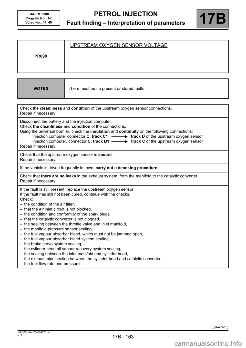
PR098
UPSTREAM OXYGEN SENSOR VOLTAGE
NOTESThere must be no present or stored faults.
Check the cleanliness and condition of the upstream oxygen sensor connections.
Repair if necessary.
Disconnect the battery and the injection computer.
Check the cleanliness and condition of the connections.
Using the universal bornier, check the insulation and continuity on the following connections:
Injection computer connectorC, track C1 track D of the upstream oxygen sensor
Injection computer, connectorC, track B1 track C of the upstream oxygen sensor
Repair if necessary.
Check that the upstream oxygen sensor is secure.
Repair if necessary.
If the vehicle is driven frequently in town, carry out a decoking procedure.
Check that there are no leaks in the exhaust system, from the manifold to the catalytic converter.
Repair if necessary.
If the fault is still present, replace the upstream oxygen sensor.
If the fault has still not been cured, continue with the checks.
Check:
– the condition of the air filter,
– that the air inlet circuit is not blocked,
– the condition and conformity of the spark plugs,
– that the catalytic converter is not clogged,
– the sealing between the throttle valve and inlet manifold,
– the manifold pressure sensor sealing,
– the fuel vapour absorber bleed, which must not be jammed open,
– the fuel vapour absorber bleed system sealing,
– the brake servo system sealing,
– the cylinder head oil vapour recovery system sealing,
– the sealing between the inlet manifold and cylinder head,
– the exhaust pipe sealing between the cylinder head and catalytic converter.
– the fuel flow rate and pressure.
JSAA741.0
Page:
< prev 1-8 9-16 17-24