Page 216 of 331
214Driving and operating
The boiling point depends on the
pressure and mixing ratio. At ambient pressure, it is between -42 °C (pure
propane) and -0.5 °C (pure butane).Caution
The system works at an ambient
temperature of approx. -8 °C to
100 °C.
Full function of the LPG system can
only be guaranteed with liquid gas
which complies with the minimum
requirements of DIN EN 589.
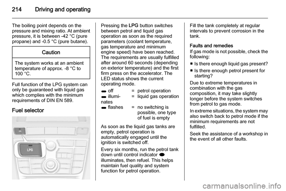
Fuel selector
Pressing the LPG button switches
between petrol and liquid gas
operation as soon as the required
parameters (coolant temperature,
gas temperature and minimum
engine speed) have been reached.
The requirements are usually fulfilled
after around 60 seconds (depending
on exterior temperature) and the first
firm press on the accelerator. The
LED status shows the current
operating mode.1 off=petrol operation1 illumi‐
nates=liquid gas operation1 flashes=no switching is
possible, one type
of fuel is empty
As soon as the liquid gas tanks are
empty, petrol operation is
automatically engaged until the
ignition is switched off.
Every six months, run the petrol tank
down until control indicator i
illuminates, then refuel. This helps
maintain fuel quality and system
function for petrol operation.
Fill the tank completely at regular
intervals to prevent corrosion in the
tank.
Faults and remedies
If gas mode is not possible, check the following:
■ Is there enough liquid gas present?
■ Is there enough petrol present for starting?
Due to extreme temperatures in
combination with the gas
composition, it may take slightly
longer before the system switches
from petrol to gas mode.
In extreme situations, the system may
also switch back to petrol mode if the
minimum requirements are not
fulfilled.
Seek the assistance of a workshop in the event of all other faults.
Page 219 of 331
Driving and operating217
Liquid gas refuellingFollow the operating and safety
instructions of the filling station when
refuelling.
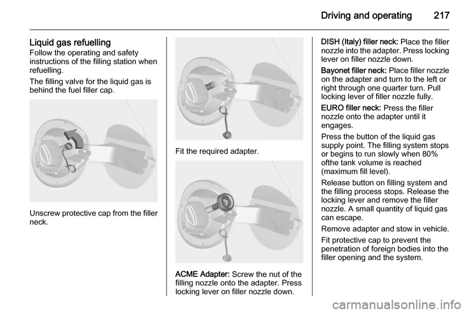
The filling valve for the liquid gas is
behind the fuel filler cap.
Unscrew protective cap from the filler
neck.
Fit the required adapter.
ACME Adapter: Screw the nut of the
filling nozzle onto the adapter. Press
locking lever on filler nozzle down.
DISH (Italy) filler neck: Place the filler
nozzle into the adapter. Press locking lever on filler nozzle down.
Bayonet filler neck: Place filler nozzle
on the adapter and turn to the left or
right through one quarter turn. Pull
locking lever of filler nozzle fully.
EURO filler neck: Press the filler
nozzle onto the adapter until it
engages.
Press the button of the liquid gas supply point. The filling system stops
or begins to run slowly when 80%
ofthe tank volume is reached
(maximum fill level).
Release button on filling system and
the filling process stops. Release the
locking lever and remove the filler
nozzle. A small quantity of liquid gas
can escape.
Remove adapter and stow in vehicle.
Fit protective cap to prevent the
penetration of foreign bodies into the
filler opening and the system.
Page 233 of 331
Vehicle care231
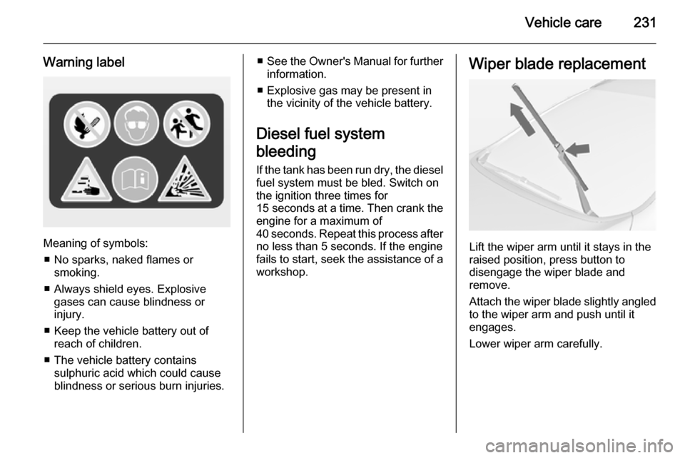
Warning label
Meaning of symbols:■ No sparks, naked flames or smoking.
■ Always shield eyes. Explosive gases can cause blindness or
injury.
■ Keep the vehicle battery out of reach of children.
■ The vehicle battery contains sulphuric acid which could cause
blindness or serious burn injuries.
■ See the Owner's Manual for further
information.
■ Explosive gas may be present in the vicinity of the vehicle battery.
Diesel fuel system
bleeding
If the tank has been run dry, the diesel
fuel system must be bled. Switch on
the ignition three times for
15 seconds at a time. Then crank the
engine for a maximum of
40 seconds. Repeat this process after
no less than 5 seconds. If the engine fails to start, seek the assistance of a
workshop.Wiper blade replacement
Lift the wiper arm until it stays in the
raised position, press button to
disengage the wiper blade and
remove.
Attach the wiper blade slightly angled
to the wiper arm and push until it
engages.
Lower wiper arm carefully.
Page 264 of 331
262Vehicle care
The menu can be selected by thebuttons on the turn signal lever.
Press the MENU button to select the
Vehicle Information Menu X.
Turn the adjuster wheel to select the
tyre pressure monitoring system.
System status and pressure warnings
are displayed by a message with the
corresponding tyre flashing in the
Driver Information Centre.A detected low tyre pressure
condition is indicated by the control
indicator w 3 119.
If w illuminates, stop as soon as
possible and inflate the tyres as
recommended 3 309.
After inflating, driving may be
required to update the tyre pressure
values in the DIC. During this time w
may illuminate.
If w illuminates at lower temperatures
and extinguishes after some driving,
this could be an indicator for getting low pressure. Check tyre pressure.
Vehicle messages 3 128.
Page 269 of 331
Vehicle care267
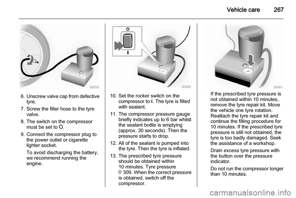
6.Unscrew valve cap from defective
tyre.
7. Screw the filler hose to the tyre valve.
8. The switch on the compressor must be set to J.
9. Connect the compressor plug to the power outlet or cigarette
lighter socket.
To avoid discharging the battery,
we recommend running the
engine.10. Set the rocker switch on the compressor to I. The tyre is filled
with sealant.
11. The compressor pressure gauge briefly indicates up to 6 bar whilstthe sealant bottle is emptying
(approx. 30 seconds). Then the
pressure starts to drop.
12. All of the sealant is pumped into the tyre. Then the tyre is inflated.
13. The prescribed tyre pressure should be obtained within
10 minutes. Tyre pressure
3 309 . When the correct pressure
is obtained, switch off the compressor.If the prescribed tyre pressure is
not obtained within 10 minutes,
remove the tyre repair kit. Move
the vehicle one tyre rotation.
Reattach the tyre repair kit and
continue the filling procedure for
10 minutes. If the prescribed tyre pressure is still not obtained, the
tyre is too badly damaged. Seek
the assistance of a workshop.
Drain excess tyre pressure with
the button over the pressure
indicator.
Do not run the compressor longer than 10 minutes.
Page 275 of 331
Vehicle care273Caution
The use of a spare wheel that issmaller than the other wheels or in combination with winter tyres
could affect driveability. Have the defective tyre replaced as soon as
possible.
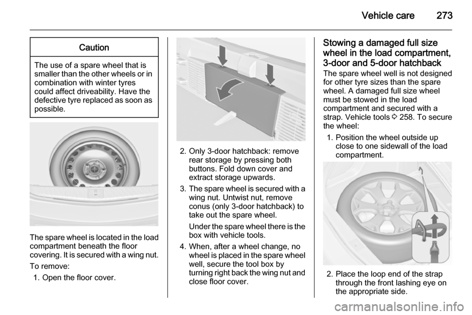
The spare wheel is located in the load
compartment beneath the floor
covering. It is secured with a wing nut.
To remove:
1. Open the floor cover.
2. Only 3-door hatchback: remove rear storage by pressing both
buttons. Fold down cover and
extract storage upwards.
3. The spare wheel is secured with a
wing nut. Untwist nut, remove
conus (only 3-door hatchback) to
take out the spare wheel.
Under the spare wheel there is the box with vehicle tools.
4. When, after a wheel change, no wheel is placed in the spare wheel
well, secure the tool box by
turning right back the wing nut and close floor cover.
Stowing a damaged full size
wheel in the load compartment,
3-door and 5-door hatchback
The spare wheel well is not designed
for other tyre sizes than the spare
wheel. A damaged full size wheel
must be stowed in the load
compartment and secured with a
strap. Vehicle tools 3 258. To secure
the wheel:
1. Position the wheel outside up close to one sidewall of the load
compartment.
2. Place the loop end of the strap through the front lashing eye on
the appropriate side.