2014 NISSAN TEANA battery
[x] Cancel search: batteryPage 3273 of 4801

MWI-18
< SYSTEM DESCRIPTION >
DIAGNOSIS SYSTEM (METER)
DIAGNOSIS SYSTEM (METER)
DescriptionINFOID:0000000009461692
COMBINATION METER SELF-DIAGNOSIS MODE
The following meter functions can be checked during Combination Meter Self-Diagnosis Mode:
• Pointer sweep of speedometer, tachometer and gauges.
• Illumination of all LCD segments and color patterns for meter displays.
• Illumination of all lamps/LEDs that are controlled by the combination meter (regardless of switch status).
STARTING COMBINATION METER SELF-DIAGNOSIS MODE
NOTE:
• Check combination meter power supply and ground circuits if self-diagnosis mode does not start. Refer to
MWI-58, "COMBINATION METER : Diagnosis Procedure"
. Replace combination meter if power supply and
ground circuits are found to be normal and self-diagnosis mode does not start. Refer to MWI-82, "Removal
and Installation".
• Combination meter self-diagnosis mode will function with t he ignition switch in ON. Combination meter self-
diagnosis mode will exit upon turning the ignition switch to OFF.
How to Initiate Self-Diagnosis Mode
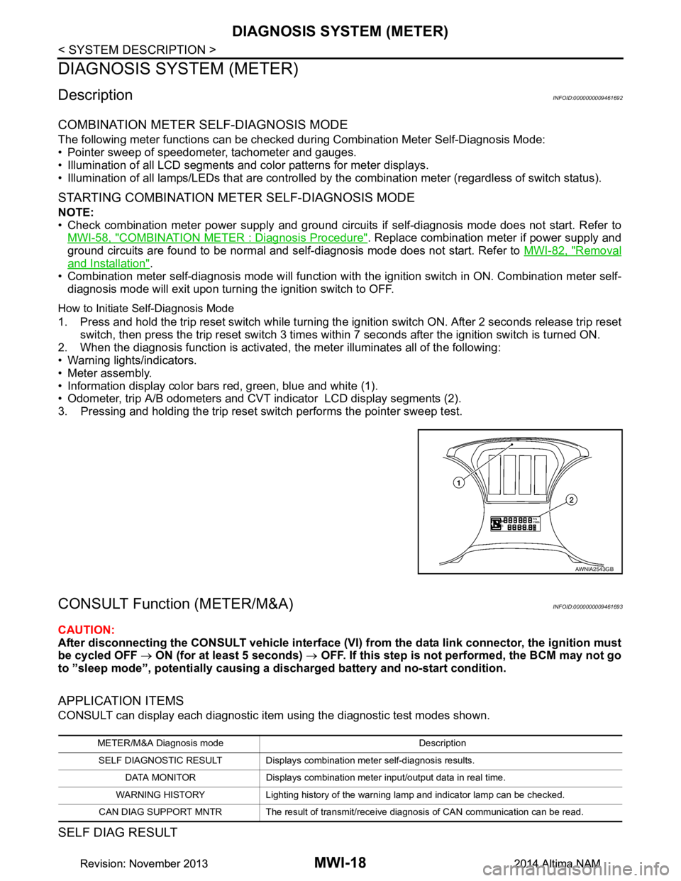
1. Press and hold the trip reset switch while turning the ignition switch ON. After 2 seconds release trip reset switch, then press the trip reset switch 3 times within 7 seconds after the ignition switch is turned ON.
2. When the diagnosis function is activated, the meter illuminates all of the following:
• Warning lights/indicators.
• Meter assembly.
• Information display color bars red, green, blue and white (1).
• Odometer, trip A/B odometers and CVT indicator LCD display segments (2).
3. Pressing and holding the trip reset switch performs the pointer sweep test.
CONSULT Function (METER/M&A)INFOID:0000000009461693
CAUTION:
After disconnecting the CONSULT vehicle interface (VI) from the data link connector, the ignition must
be cycled OFF → ON (for at least 5 seconds) → OFF. If this step is not performed, the BCM may not go
to ”sleep mode”, potentially causing a di scharged battery and no-start condition.
APPLICATION ITEMS
CONSULT can display each diagnostic item using the diagnostic test modes shown.
SELF DIAG RESULT
AWNIA2543GB
METER/M&A Diagnosis mode Description
SELF DIAGNOSTIC RESULT Displays combin ation meter self-diagnosis results.
DATA MONITOR Displays combination meter input/output data in real time.
WARNING HISTORY Lighting history of the warning lamp and indicator lamp can be checked.
CAN DIAG SUPPORT MNTR The result of transmit/receive diagnosis of CAN communication can be read.
Revision: November 20132014 Altima NAMRevision: November 20132014 Altima NAM
Page 3279 of 4801

MWI-24
< ECU DIAGNOSIS INFORMATION >
COMBINATION METER
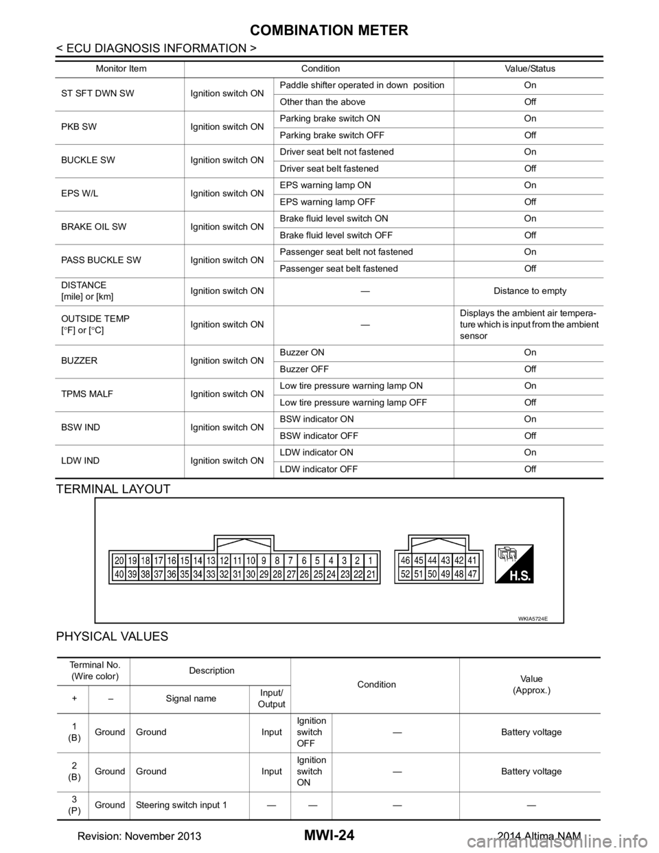
TERMINAL LAYOUT
PHYSICAL VALUES
ST SFT DWN SW Ignition switch ON Paddle shifter operated in down position On
Other than the above Off
PKB SW Ignition switch ON Parking brake switch ON On
Parking brake switch OFF Off
BUCKLE SW Ignition switch ON Driver seat belt not fastened On
Driver seat belt fastened Off
EPS W/L Ignition switch ON EPS warning lamp ON On
EPS warning lamp OFF Off
BRAKE OIL SW Ignition switch ON Brake fluid level switch ON On
Brake fluid level switch OFF Off
PASS BUCKLE SW Ignition switch ON Passenger seat belt not fastened On
Passenger seat belt fastened Off
DISTANCE
[mile] or [km] Ignition switch ON — Distance to empty
OUTSIDE TEMP
[ ° F] or [ °C] Ignition switch ON — Displays the ambient air tempera-
ture which is input from the ambient
sensor
BUZZER Ignition switch ON Buzzer ON On
Buzzer OFF Off
TPMS MALF Ignition switch ON Low tire pressure
warning lamp ON On
Low tire pressure warning lamp OFF Off
BSW IND Ignition switch ON BSW indicator ON On
BSW indicator OFF Off
LDW IND Ignition switch ON LDW indicator ON On
LDW indicator OFF Off
Monitor Item Condition Value/Status
WKIA5724E
Te r m i n a l N o .
(Wire color) Description
ConditionVa l u e
(Approx.)
+ – Signal name Input/
Output
1
(B) Ground Ground Input Ignition
switch
OFF — Battery voltage
2
(B) Ground Ground Input Ignition
switch
ON — Battery voltage
3
(P) Ground Steering switch input 1 — — — —
Revision: November 20132014 Altima NAMRevision: November 20132014 Altima NAM
Page 3280 of 4801

MWI
COMBINATION METERMWI-25
< ECU DIAGNOSIS INFORMATION >
C
D E
F
G H
I
J
K L
M B
A
O P
4
(R) Ground Steering switch input 2 — — — —
5
(P) Ground ACC — Ignition
switch
ON Ignition switch ACC or ON
power supply Battery voltage
6
(G) Ground Security signal Input Ignition
switch
ON Security indicator ON 0 V
Security indicator OFF 12 V
7
(R) Ground Air bag signal Input Ignition
switch
ON Air bag warning lamp
ON —
Air bag warning lamp
OFF —
8
(W) Ground
Passenger seat belt warn-
ing signal InputIgnition
switch
ON Fastened 12 V
Unfastened 0 V
9
(V) Ground Seat belt buckle switch sig-
nal (driver seat) InputIgnition
switch
ON Fastened 12 V
Unfastened 0 V
11
(R) Ground Alternator signal Input Ignition
switch
ON Charge warning lamp ON 2 V
Charge warning lamp OFF Battery voltage
12
(G) Ground Parking brake switch signal Input Ignition
switch
ON Parking brake applied 0 V
Parking brake released 12 V
18
(BR) Ground AC PD cut Input Ignition
switch
ON Signal ON 0 V
Signal OFF 5 V
21
(BR) —Ignition — Ignition
switch
ON or
START —12 V
22
(G) — Battery power supply — Ignition
switch
OFF —Battery voltage
23
(GR) Ground Illumination control output
signal —Ignition
switch
ON —0 V
24
(W) Ground Steering switch ground — Ignition
switch
ON —0 V
25
(BR) Ground Brake fluid level switch Input Ignition
switch
ON Brake fluid level low 0 V
Brake fluid level normal Battery voltage
26
(R) Ground Fuel level sensor ground — Ignition
switch
ON —0 V
27
(W) Ground Fuel level sensor signal — — — —
30
(L) Ground Ambient sensor signal
(without auto A/C) InputIgnition
switch
ON —
0-5 V
(based on ambient temperature)
Te r m i n a l N o .
(Wire color) Description
ConditionVa l u e
(Approx.)
+ – Signal name Input/
Output
Revision: November 20132014 Altima NAMRevision: November 20132014 Altima NAM
Page 3313 of 4801

MWI-58
< DTC/CIRCUIT DIAGNOSIS >
POWER SUPPLY AND GROUND CIRCUIT
POWER SUPPLY AND GROUND CIRCUIT
COMBINATION METER
COMBINATION METER : Diagnosis ProcedureINFOID:0000000009461715
Regarding Wiring Diagram information, refer to MWI-32, "Wiring Diagram".
1.CHECK FUSES
Check that the following fuses are not blown.
Is the fuse blown?
YES >> Replace the blown fuse after repairing the affected circuit.
NO >> GO TO 2.
2.POWER SUPPLY CIRCUIT CHECK
1. Disconnect combination meter connector.
2. Check voltage between combination meter har ness connector M24 terminals 5, 21, 22 and ground.
Is the inspection result normal?
YES >> GO TO 3.
NO >> Repair or replace harness or connectors.
3.GROUND CIRCUIT CHECK
1. Turn ignition switch OFF.
2. Check continuity between combination mete r harness connector M24 terminals 1, 2 and ground.
Is the inspection result normal?
YES >> Inspection End.
NO >> Repair or replace harness or connectors.
BCM (BODY CONTROL MODULE)
BCM (BODY CONTROL MODULE) : Diagnosis ProcedureINFOID:0000000009940932
Regarding Wiring Diagram information, refer to BCS-55, "Wiring Diagram".
Unit Power source Fuse No.
Combination meter Battery 13
25
Ignition switch ON or START 31
Terminals Ignition switch position
(+) (–) OFF ACC ON START
Connector Terminal
M24 22
GroundBattery voltage Battery voltage Battery voltage Battery voltage
21 0V 0V Battery voltage Battery voltage 5 0V Battery voltage Battery voltage 0V
Te r m i n a l s Continuity
(+)
(–)
Connector Terminal
M24 1
Ground Yes
2
Revision: November 20132014 Altima NAMRevision: November 20132014 Altima NAM
Page 3314 of 4801

MWI
POWER SUPPLY AND GROUND CIRCUITMWI-59
< DTC/CIRCUIT DIAGNOSIS >
C
D E
F
G H
I
J
K L
M B
A
O P
1. CHECK FUSE AND FUSIBLE LINK
Check that the following fuse and fusible link are not blown.
Is the fuse or fusible link blown?
YES >> Replace the blown fuse or fusible link after repairing the affected circuit.
NO >> GO TO 2
2. CHECK POWER SUPPLY CIRCUIT
1. Disconnect BCM connector M21.
2. Check voltage between BCM connector M21 terminals 131, 139 and ground.
Is the inspection result normal?
YES >> GO TO 3
NO >> Repair or replace harness or connectors.
3. CHECK GROUND CIRCUIT
Check continuity between BCM connector M21 terminals 134, 143 and ground.
Is the inspection result normal?
YES >> Inspection End.
NO >> Repair or replace harness or connectors.
IPDM E/R (INTELLIGENT POWER DIST RIBUTION MODULE ENGINE ROOM)
IPDM E/R (INTELLIGENT POWER DISTRIBUTION MODULE ENGINE ROOM) : Di-
agnosis Procedure
INFOID:0000000009940785
Regarding Wiring Diagram information, refer to PCS-21, "Wiring Diagram".
1. CHECK FUSIBLE LINKS
Check that the following fusible links are not blown.
Is the fusible link blown?
Terminal No. Signal name Fuse and fusible link No.
139 Fusible link battery power I (40A)
131 BCM battery fuse 1 (10A)
BCM GroundVo l ta g e
(Approx.)
Connector Terminal
M21 131
—Batteryvoltage
139
BCM Ground Continuity
Connector Terminal
M21 134
—Yes
143
Terminal No. Signal name Fusible link No.
1 Fusible link main E (80A)
2 Fusible link IPDM E/R A (250A), C (80A)
3 Fusible link ignition switch A (250A), B (100A), M (40A)
Revision: November 20132014 Altima NAMRevision: November 20132014 Altima NAM
Page 3315 of 4801

MWI-60
< DTC/CIRCUIT DIAGNOSIS >
POWER SUPPLY AND GROUND CIRCUIT
YES >> Replace the blown fusible link after repairing the affected circuit.
NO >> GO TO 2
2. CHECK POWER SUPPLY CIRCUIT
1. Disconnect IPDM E/R connectors E16 and E17.
2. Check voltage between IPDM E/R connectors and ground.
Is the inspection result normal?
YES >> GO TO 3
NO >> Repair or replace harness or connectors.
3. CHECK GROUND CIRCUIT
1. Disconnect IPDM E/R connectors E18 and E63.
2. Check continuity between IPDM E/R connectors and ground.
Is the inspection result normal?
YES >> Inspection End.
NO >> Repair or replace harness or connectors.
IPDM E/R GroundVo l ta g e
(Approx.)
Connector Terminal
E16 1
—Batteryvoltage
2
E17 3
IPDM E/R Ground Continuity
Connector Terminal
E18 7 —Yes
E63 41
Revision: November 20132014 Altima NAMRevision: November 20132014 Altima NAM
Page 3337 of 4801

MWI-82
< REMOVAL AND INSTALLATION >
COMBINATION METER
REMOVAL AND INSTALLATION
COMBINATION METER
Removal and InstallationINFOID:0000000009461757
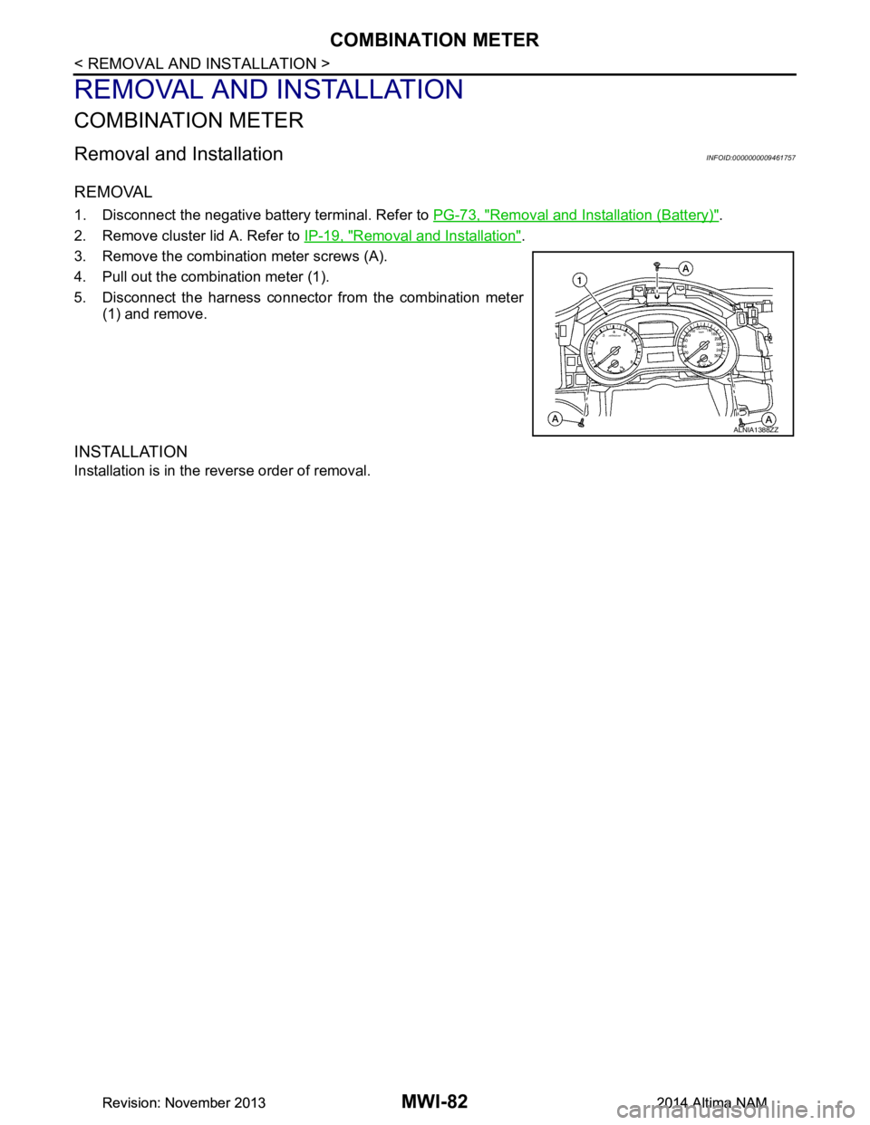
REMOVAL
1. Disconnect the negative battery terminal. Refer to PG-73, "Removal and Installation (Battery)".
2. Remove cluster lid A. Refer to IP-19, "Removal and Installation"
.
3. Remove the combination meter screws (A).
4. Pull out the combination meter (1).
5. Disconnect the harness connector from the combination meter (1) and remove.
INSTALLATION
Installation is in the reverse order of removal.
ALNIA1388ZZ
Revision: November 20132014 Altima NAMRevision: November 20132014 Altima NAM
Page 3340 of 4801

PB-2
< PRECAUTION >
PRECAUTIONS
PRECAUTION
PRECAUTIONS
Precaution for Supplemental Restraint System (SRS) "AIR BAG" and "SEAT BELT
PRE-TENSIONER"
INFOID:0000000009951710
The Supplemental Restraint System such as “A IR BAG” and “SEAT BELT PRE-TENSIONER”, used along
with a front seat belt, helps to reduce the risk or severi ty of injury to the driver and front passenger for certain
types of collision. Information necessary to service the system safely is included in the SR and SB section of
this Service Manual.
WARNING:
• To avoid rendering the SRS inopera tive, which could increase the risk of personal injury or death in
the event of a collision which would result in air bag inflation, all maintenance must be performed by
an authorized NISS AN/INFINITI dealer.
• Improper maintenance, including in correct removal and installation of the SRS, can lead to personal
injury caused by unintent ional activation of the system. For re moval of Spiral Cable and Air Bag
Module, see the SR section.
• Do not use electrical test equipmen t on any circuit related to the SRS unless instructed to in this
Service Manual. SRS wiring harn esses can be identified by yellow and/or orange harnesses or har-
ness connectors.
PRECAUTIONS WHEN USING POWER TOOLS (AIR OR ELECTRIC) AND HAMMERS
WARNING:
• When working near the Airbag Diagnosis Sensor Unit or other Airbag System sensors with the Igni-
tion ON or engine running, DO NOT use air or electri c power tools or strike near the sensor(s) with a
hammer. Heavy vibration could activate the sensor( s) and deploy the air bag(s), possibly causing
serious injury.
• When using air or electric power tools or hammers , always switch the Ignition OFF, disconnect the
battery and wait at least three minutes before performing any service.
Revision: November 20132014 Altima NAM