Page 4725 of 4801
WT-50
< SYMPTOM DIAGNOSIS >
LOW TIRE PRESSURE WARNING LAMP STAYS ON
LOW TIRE PRESSURE WARNING LAMP STAYS ON
Low Tire Pressure Warning Lamp Stays On When Ignition Switch Is Turned On
INFOID:0000000009464516
1.CHECK BCM CONNECTORS
1. Turn ignition switch OFF.
2. Disconnect BCM connectors.
3. Check terminals for damage or loose connections.
Is the inspection result normal?
YES >> GO TO 2
NO >> Repair or replace damaged connectors.
2.BCM POWER SUPPLY AND GROUND CIRCUITS
Check BCM power supply and ground circuits. Refer to BCS-74, "Diagnosis Procedure"
.
Is the inspection result normal?
YES >> Replace BCM. Refer to BCS-80, "Removal and Installation".
NO >> Repair BCM circuits.
Revision: November 20132014 Altima NAMRevision: November 20132014 Altima NAM
Page 4727 of 4801

WT-52
< SYMPTOM DIAGNOSIS >
NOISE, VIBRATION AND HARSHNESS (NVH) TROUBLESHOOTING
NOISE, VIBRATION AND HARSHNESS (NVH) TROUBLESHOOTING
NVH Troubleshooting ChartINFOID:0000000009464519
Use chart below to help you find the cause of the symp tom. If necessary, repair or replace these parts.
×: ApplicableReference page
WT-55, "Adjustment"WT-53, "Inspection"WT-55, "Adjustment"
WT-60, "Tire"
—
—
—
WT-60, "Tire"
FAX-5, "NVH Troubleshooting Chart"
,
FSU-6, "NVH Troubleshooting Chart"
RAX-4, "NVH Troubleshooting Chart"
,
RSU-4, "NVH Troubleshooting Chart"
Refer to TIRES in this chart.
Refer to ROAD WHEEL in this chart.
FAX-5, "NVH Troubleshooting Chart"
BR-6, "NVH Troubleshooting Chart"ST-29, "NVH Troubleshooting Chart"
Possible cause and SUSPECTED
PA R T S
Improper installation, looseness
Out-of-round
Imbalance
Incorrect tire pressure
Uneven tire wear
Deformation or damage
Non-uniformity
Incorrect tire size
FRONT AXLE AND FRONT SUSPENSION
REAR AXLE AND REAR SUSPENSION
TIRES
ROAD WHEELS
DRIVE SHAFT
BRAKE
STEERING
Symptom TIRESNoise
××××××× × × ××××
Shake ×××××× × × × ××××
Vibration ××××××
Shimmy ×××××××× × × × ××
Shudder ×××××× × × × × ××
Poor quality ride
or handling ×××××× × × ××
ROAD
WHEEL Noise
×× × × × × × × × ×
Shake ×× × × × × × × × ×
Shimmy, Shud-
der ×××× ×××××
Poor quality ride
or handling ×× × × × × ×
Revision: November 20132014 Altima NAMRevision: November 20132014 Altima NAM
Page 4729 of 4801
WT-54
< REMOVAL AND INSTALLATION >
REMOTE KEYLESS ENTRY RECEIVER
REMOVAL AND INSTALLATION
REMOTE KEYLESS ENTRY RECEIVER
Removal and InstallationINFOID:0000000009464521
The Tire Pressure Receiver is an integral part of the Remote Keyless Entry Receiver. Refer to DLK-224,
"Removal and Installation".
Revision: November 20132014 Altima NAMRevision: November 20132014 Altima NAM
Page 4732 of 4801

TIRE PRESSURE SENSORWT-57
< UNIT REMOVAL AND INSTALLATION >
C
D
F
G H
I
J
K L
M A
B
WT
N
O P
UNIT REMOVAL AND INSTALLATION
TIRE PRESSURE SENSOR
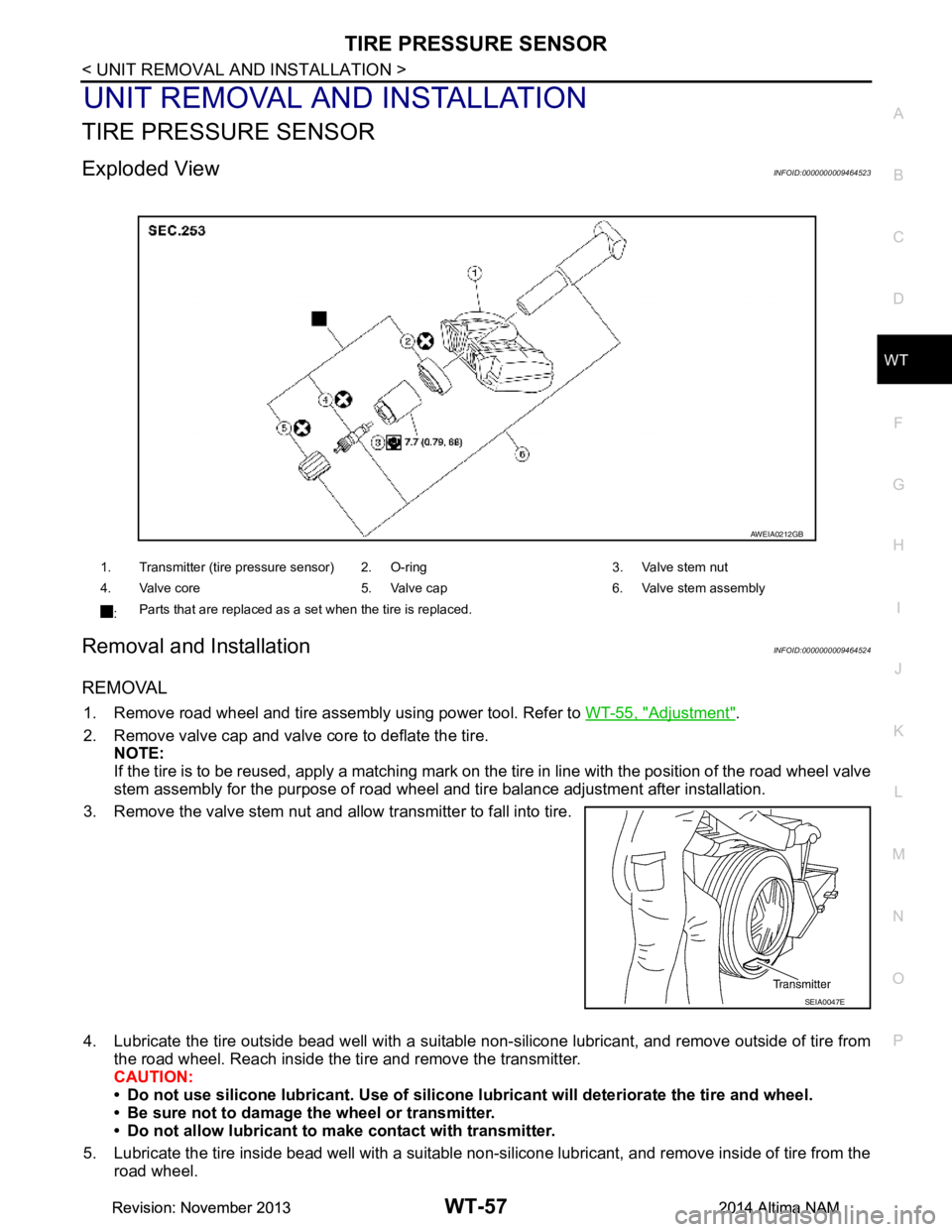
Exploded ViewINFOID:0000000009464523
Removal and InstallationINFOID:0000000009464524
REMOVAL
1. Remove road wheel and tire assembly using power tool. Refer to WT-55, "Adjustment".
2. Remove valve cap and valve core to deflate the tire. NOTE:
If the tire is to be reused, apply a matching mark on t he tire in line with the position of the road wheel valve
stem assembly for the purpose of road wheel and tire balance adjustment after installation.
3. Remove the valve stem nut and allow transmitter to fall into tire.
4. Lubricate the tire outside bead well with a suitable non-silicone lubricant, and remove outside of tire from the road wheel. Reach inside the ti re and remove the transmitter.
CAUTION:
• Do not use silicone lubricant. Use of silicone lubricant will deteriorate the tire and wheel.
• Be sure not to damage the wheel or transmitter.
• Do not allow lubricant to make contact with transmitter.
5. Lubricate the tire inside bead well with a suitable non-silicone lubricant, and remove inside of tire from the road wheel.
1. Transmitter (tire pressure sensor) 2. O-ring 3. Valve stem nut
4. Valve core 5. Valve cap 6. Valve stem assembly
: Parts that are replaced as a set when the tire is replaced.
AWEIA0212GB
SEIA0047E
Revision: November 20132014 Altima NAMRevision: November 20132014 Altima NAM
Page 4733 of 4801
WT-58
< UNIT REMOVAL AND INSTALLATION >
TIRE PRESSURE SENSOR
CAUTION:
• Do not use silicone lubricant. Use of silicone lubricant will deteriorate the tire and wheel.
• Be sure not to damage the wheel.
6. Remove the valve stem from the transmitter as shown.
INSTALLATION
1. Apply a suitable non-silicone lubricant to the tire inside bead.
CAUTION:
Do not use silicone lubr icant. Use of silicone lubricant wi ll deteriorate the tire and wheel.
2. Install the tire inside bead (1) onto the road wheel (2) in the posi- tion shown.
3. Install the valve stem to the transmitter.
4. Install the O-ring to the transmitter. CAUTION:
• Do not reuse O-ring.
• Insert O-ring to the base of the transmitter.
• The base of the valve stem (A) must be positioned in the groove of the metal plate as shown.
JSEIA0378ZZ
JPEIC0105ZZ
JSEIA0376GB
Revision: November 20132014 Altima NAMRevision: November 20132014 Altima NAM
Page 4734 of 4801

TIRE PRESSURE SENSORWT-59
< UNIT REMOVAL AND INSTALLATION >
C
D
F
G H
I
J
K L
M A
B
WT
N
O P
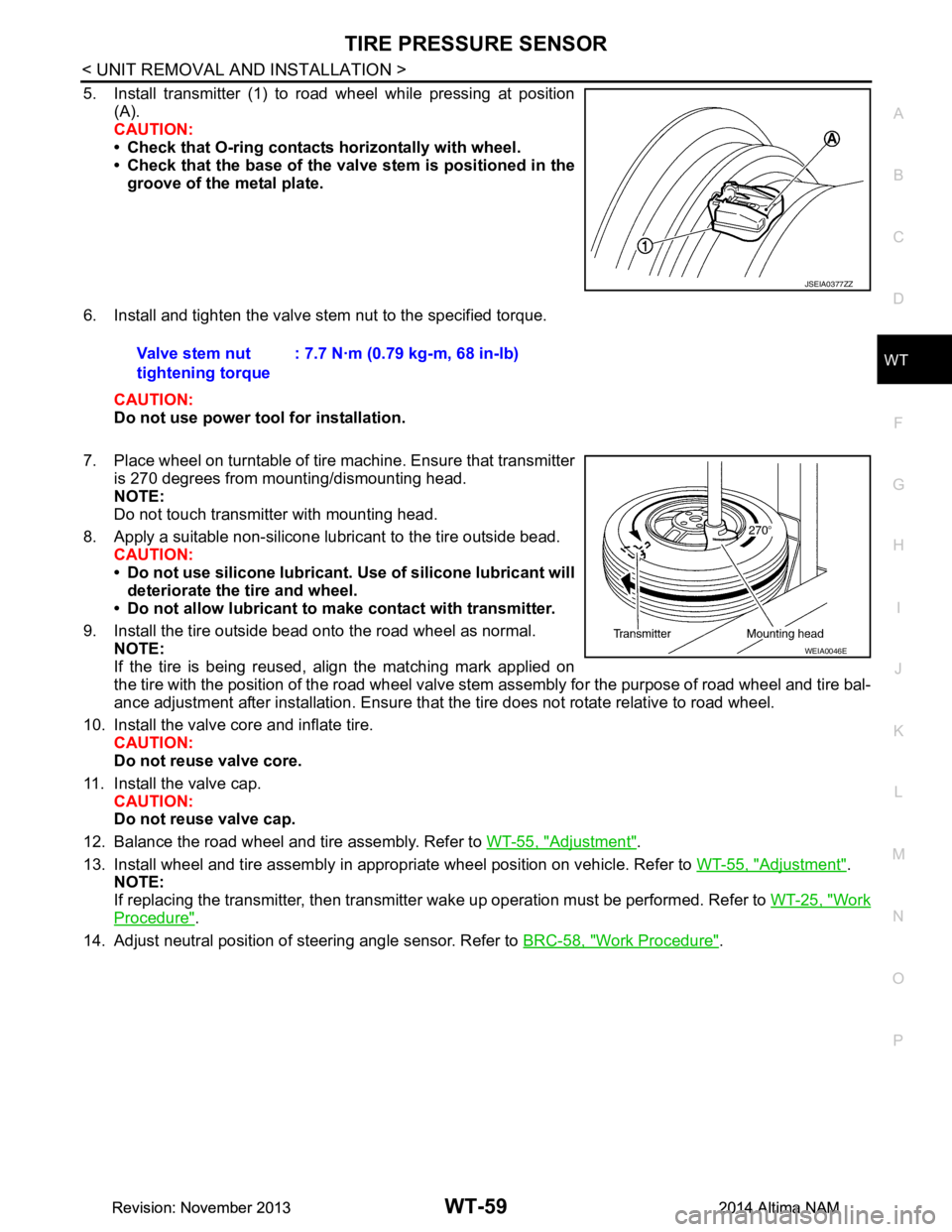
5. Install transmitter (1) to road wheel while pressing at position (A).
CAUTION:
• Check that O-ring contacts horizontally with wheel.
• Check that the base of the valve stem is positioned in the
groove of the metal plate.
6. Install and tighten the valve stem nut to the specified torque. CAUTION:
Do not use power tool for installation.
7. Place wheel on turntable of tire machine. Ensure that transmitter
is 270 degrees from mounting/dismounting head.
NOTE:
Do not touch transmitter with mounting head.
8. Apply a suitable non-silicone lubricant to the tire outside bead. CAUTION:
• Do not use silicone lubricant. Use of silicone lubricant will
deteriorate the tire and wheel.
• Do not allow lubricant to make contact with transmitter.
9. Install the tire outside bead onto the road wheel as normal. NOTE:
If the tire is being reused, align the matching mark applied on
the tire with the position of the road wheel valve st em assembly for the purpose of road wheel and tire bal-
ance adjustment after installation. Ensure that the tire does not rotate relative to road wheel.
10. Install the valve core and inflate tire. CAUTION:
Do not reuse valve core.
11. Install the valve cap. CAUTION:
Do not reuse valve cap.
12. Balance the road wheel and tire assembly. Refer to WT-55, "Adjustment"
.
13. Install wheel and tire assembly in appropriate wheel position on vehicle. Refer to WT-55, "Adjustment"
.
NOTE:
If replacing the transmitter, then transmitter wake up operation must be performed. Refer to WT-25, "Work
Procedure".
14. Adjust neutral position of steering angle sensor. Refer to BRC-58, "Work Procedure"
.
JSEIA0377ZZ
Valve stem nut
tightening torque : 7.7 N·m (0.79 kg-m, 68 in-lb)
WEIA0046E
Revision: November 20132014 Altima NAMRevision: November 20132014 Altima NAM
Page 4735 of 4801
WT-60
< SERVICE DATA AND SPECIFICATIONS (SDS)
SERVICE DATA AND SPECIFICATIONS (SDS)
SERVICE DATA AND SPECIFICATIONS (SDS)
SERVICE DATA AND SPECIFICATIONS (SDS)
Road WheelINFOID:0000000009464525
TireINFOID:0000000009464526
Unit: kPa (kg/cm2, psi)
Standard itemAllowable value
Aluminum Steel Inside Outside
Radial runout Lateral deflection Less than 0.3 mm (0.012 in)
Less than 0.8 mm
(0.031 in) Less than 0.4 mm
(0.016 in)
Radial deflection Less than 0.3 mm (0.012 in) Less than 1.0 mm
(0.039 in) Less than 0.9 mm
(0.035 in)
Allowable imbalance Dynamic
(At rim flange) Less than 5 g (0.18 oz) (one side)
Stati c
(At rim flange) Less than 10 g (0.35 oz)
Wheel nut tightening
torque 113 N·m (12 kg-m, 83 ft-lb)
Tire size Air pressure
Front tire Rear tire
215/60R16 220 (2.2, 32) 220 (2.2, 32)
215/55R17 230 (2.3, 33) 230 (2.3, 33)
235/45R18 230 (2.3, 33) 230 (2.3, 33)
Revision: November 20132014 Altima NAMRevision: November 20132014 Altima NAM
Page 4746 of 4801

DIAGNOSIS SYSTEM (BCM)WW-11
< SYSTEM DESCRIPTION >
C
D E
F
G H
I
J
K
M A
B
WW
N
O P
WIPER
WIPER : CONSULT Func tion (BCM - WIPER)INFOID:0000000009944152
CAUTION:
After disconnecting the CONSULT vehicle interface (VI) from the data link connector, the ignition must
be cycled OFF → ON (for at least 5 seconds) → OFF. If this step is not performed, the BCM may not go
to ”sleep mode”, potentiall y causing a discharged battery and a no-start condition.
DATA MONITOR
ACTIVE TEST
WORK SUPPORT
* : Initial setting RAP system RETAINED PWR
×
Signal buffer system SIGNAL BUFFER ×
TPMS AIR PRESSURE MONITOR ××××
System Sub System
Direct Diagnostic Mode
Ecu Identification
Self Diagnostic Result
Data Monitor
Active Test
Work support
Configuration
CAN Diag Support Mntr
Monitor Item [Unit] Description
PUSH SW [On/Off] Indicates condition of push-button ignition switch.
VEH SPEED 1 [km/h] Indicates vehicle speed signal received from ABS on CAN communication line.
FR WIPER HI [On/Off]
Indicates condition of wiper operation of combination switch.
FR WIPER LOW [On/Off]
FR WASHER SW [On/Off]
FR WIPER INT [On/Off]
FR WIPER STOP [On/Off] Indicates front wiper auto stop signal received from IPDM E/R on CAN communication
line.
INT VOLUME [1 − 7] Indicates condition of intermittent wiper operation of combination switch.
Test Item Description
FR WIPER This test is able to check front wiper operation [Hi/Lo/INT/Off].
Support Item Setting Description
WIPER SPEED SETTING On Front wiper intermittent time linked with vehicle speed and wiper dial position.
Off* Front wiper intermittent time linked with wiper dial position.
Revision: November 20132014 Altima NAMRevision: November 20132014 Altima NAM