2014 NISSAN TEANA low beam
[x] Cancel search: low beamPage 2395 of 4801

FRONT COMBINATION LAMPEXL-129
< REMOVAL AND INSTALLATION >
C
D E
F
G H
I
J
K
M A
B
EXL
N
O P
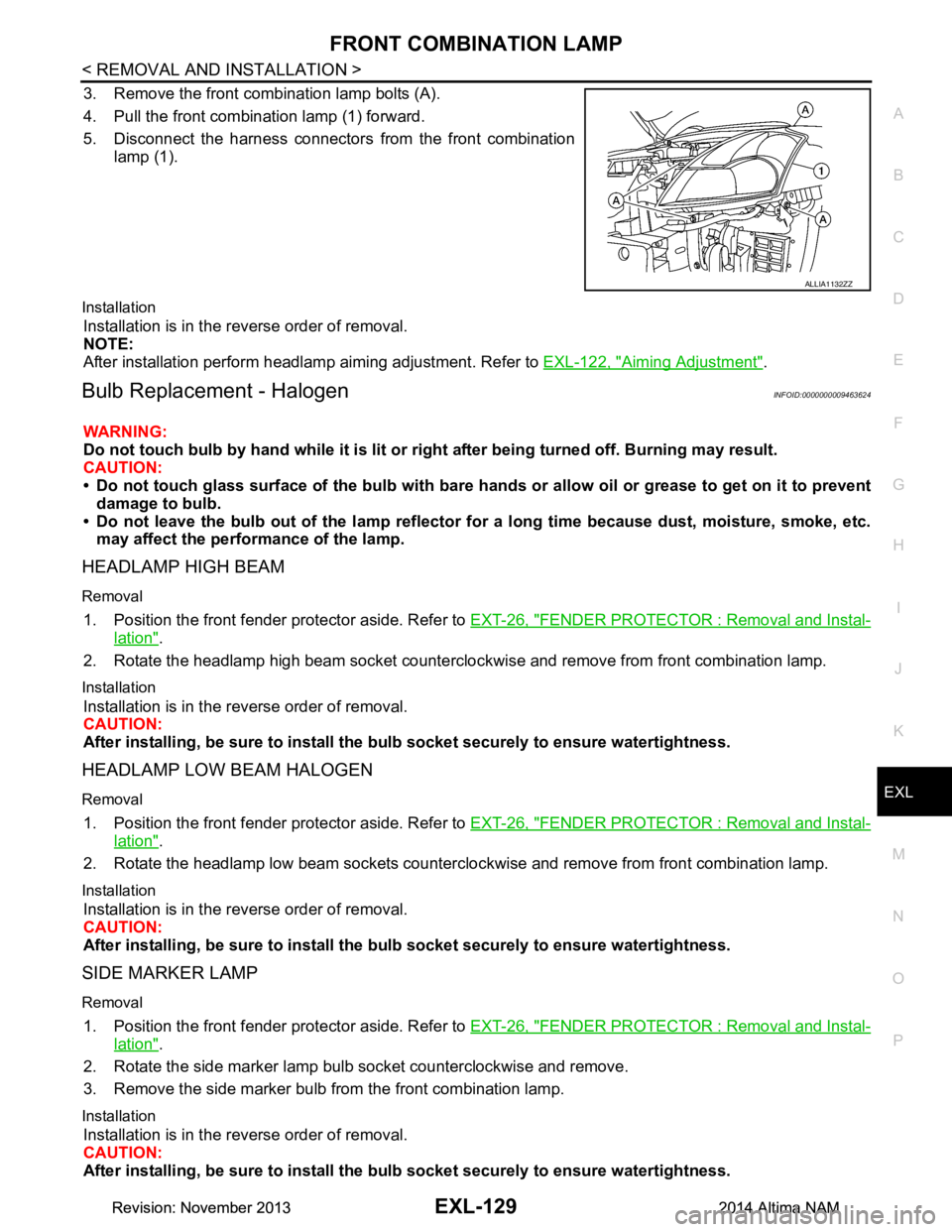
3. Remove the front combination lamp bolts (A).
4. Pull the front combination lamp (1) forward.
5. Disconnect the harness connectors from the front combination
lamp (1).
Installation
Installation is in the reverse order of removal.
NOTE:
After installation perform headlamp aiming adjustment. Refer to EXL-122, "Aiming Adjustment"
.
Bulb Replacement - HalogenINFOID:0000000009463624
WARNING:
Do not touch bulb by hand while it is lit or right after being turned off. Burning may result.
CAUTION:
• Do not touch glass surface of the bulb with bare hand s or allow oil or grease to get on it to prevent
damage to bulb.
• Do not leave the bulb out of the lamp reflector fo r a long time because dust, moisture, smoke, etc.
may affect the performance of the lamp.
HEADLAMP HIGH BEAM
Removal
1. Position the front fender pr otector aside. Refer to EXT-26, "FENDER PROTECTOR : Removal and Instal-
lation".
2. Rotate the headlamp high beam socket countercloc kwise and remove from front combination lamp.
Installation
Installation is in the reverse order of removal.
CAUTION:
After installing, be sure to install the bulb socket securely to ensure watertightness.
HEADLAMP LOW BEAM HALOGEN
Removal
1. Position the front fender protector aside. Refer to EXT-26, "FENDER PROTECTOR : Removal and Instal-
lation".
2. Rotate the headlamp low beam sockets countercloc kwise and remove from front combination lamp.
Installation
Installation is in the reverse order of removal.
CAUTION:
After installing, be sure to install the bulb socket securely to ensure watertightness.
SIDE MARKER LAMP
Removal
1. Position the front fender protector aside. Refer to EXT-26, "FENDER PROTECTOR : Removal and Instal-
lation".
2. Rotate the side marker lamp bulb socket counterclockwise and remove.
3. Remove the side marker bulb from the front combination lamp.
Installation
Installation is in the reverse order of removal.
CAUTION:
After installing, be sure to install the bulb socket securely to ensure watertightness.
ALLIA1132ZZ
Revision: November 20132014 Altima NAMRevision: November 20132014 Altima NAM
Page 2408 of 4801

EXL-142
< UNIT DISASSEMBLY AND ASSEMBLY >
FRONT COMBINATION LAMP
UNIT DISASSEMBLY AND ASSEMBLY
FRONT COMBINATION LAMP
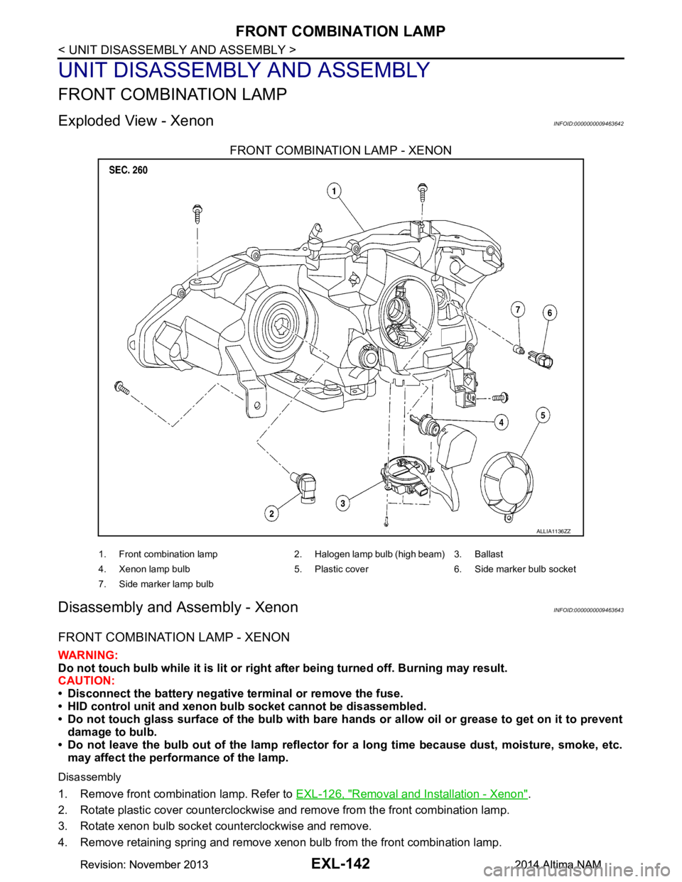
Exploded View - XenonINFOID:0000000009463642
FRONT COMBINATION LAMP - XENON
Disassembly and Assembly - XenonINFOID:0000000009463643
FRONT COMBINATION LAMP - XENON
WARNING:
Do not touch bulb while it is lit or right after being turned off. Burning may result.
CAUTION:
• Disconnect the battery negative terminal or remove the fuse.
• HID control unit and xenon bu lb socket cannot be disassembled.
• Do not touch glass surface of the bulb with bare hands or allow oil or grease to get on it to prevent
damage to bulb.
• Do not leave the bulb out of the lamp reflector fo r a long time because dust, moisture, smoke, etc.
may affect the performance of the lamp.
Disassembly
1. Remove front combination lamp. Refer to EXL-126, "Removal and Installation - Xenon".
2. Rotate plastic cover counterclockwise and remove from the front combination lamp.
3. Rotate xenon bulb socket counterclockwise and remove.
4. Remove retaining spring and remove xenon bulb from the front combination lamp.
ALLIA1136ZZ
1. Front combination lamp 2. Halogen lamp bulb (high beam) 3. Ballast
4. Xenon lamp bulb 5. Plastic cover 6. Side marker bulb socket
7. Side marker lamp bulb
Revision: November 20132014 Altima NAMRevision: November 20132014 Altima NAM
Page 2409 of 4801

FRONT COMBINATION LAMPEXL-143
< UNIT DISASSEMBLY AND ASSEMBLY >
C
D E
F
G H
I
J
K
M A
B
EXL
N
O P
5. Rotate the halogen lamp bulb (high beam) counterclockwise and remove.
6. Rotate the side marker bulb socket counterclockwise and remove.
7. Remove the side marker lamp bulb from the sidemarker bulb socket.
Assembly
Assembly is in the reverse order of disassembly.
CAUTION:
• After installing the xenon bulb, be sure to install plastic cover securely to ensure watertightness.
• After installing, be sure to install the bulb sockets securely to ensure watertightness.
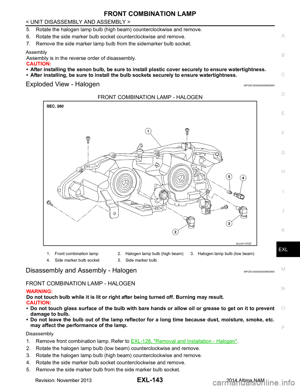
Exploded View - HalogenINFOID:0000000009463644
FRONT COMBINATION LAMP - HALOGEN
Disassembly and Assembly - HalogenINFOID:0000000009463645
FRONT COMBINATION LAMP - HALOGEN
WARNING:
Do not touch bulb while it is lit or right after being turned off. Burning may result.
CAUTION:
• Do not touch glass surface of the bulb with bare hand s or allow oil or grease to get on it to prevent
damage to bulb.
• Do not leave the bulb out of the lamp reflector fo r a long time because dust, moisture, smoke, etc.
may affect the performance of the lamp.
Disassembly
1. Remove front combination lamp. Refer to EXL-128, "Removal and Installation - Halogen".
2. Rotate the halogen lamp bulb (low beam) counterclockwise and remove.
3. Rotate the halogen lamp bulb (high beam) counterclockwise and remove.
4. Rotate the side marker bulb socket counterclockwise and remove.
5. Remove the side marker bulb from the side marker bulb socket.
ALLIA1137ZZ
1. Front combination lamp 2. Halogen lamp bulb (high beam) 3. Halogen lamp bulb (low beam)
4. Side marker bulb socket 5. Side marker bulb
Revision: November 20132014 Altima NAMRevision: November 20132014 Altima NAM
Page 2414 of 4801

EXL-148
< SERVICE DATA AND SPECIFICATIONS (SDS)
SERVICE DATA AND SPECIFICATIONS (SDS)
SERVICE DATA AND SPECIFICATIONS (SDS)
SERVICE DATA AND SPECIFICATIONS (SDS)
Bulb SpecificationsINFOID:0000000009463650
*: Always check with the Parts Department for the latest parts information.Item Wattage (W)*
Front combination lamp Low beam (halogen) 55
Low beam (xenon) 35
High beam 65
Side marker lamp 5
Turn signal/Park lamp 28/8 (amber)
Door mirror side turn signal lamp (if equipped) LED
Rear combination lamp St op /Ta il la mp
21/5
LED
Turn signal lamp 27
Back-up lamp 16
Side marker lamp 5
Fog lamp (if equipped) 55
Daytime running lamp built-in fog lamp (Canada only) 19
License plate lamp 5
High-mounted stop lamp Parcel shelf mounted LED
Rear spoiler mounted LED
Revision: November 20132014 Altima NAMRevision: November 20132014 Altima NAM
Page 2775 of 4801
![NISSAN TEANA 2014 Service Manual
HAC-126
< SYSTEM DESCRIPTION >[MANUAL AIR CONDITIONER]
DIAGNOSIS SYSTEM (IPDM E/R)
DIAGNOSIS SYSTEM (IPDM E/R)
CONSULT Function (IPDM E/R)INFOID:0000000009958324
CAUTION:
After disconnecting the CON NISSAN TEANA 2014 Service Manual
HAC-126
< SYSTEM DESCRIPTION >[MANUAL AIR CONDITIONER]
DIAGNOSIS SYSTEM (IPDM E/R)
DIAGNOSIS SYSTEM (IPDM E/R)
CONSULT Function (IPDM E/R)INFOID:0000000009958324
CAUTION:
After disconnecting the CON](/manual-img/5/57390/w960_57390-2774.png)
HAC-126
< SYSTEM DESCRIPTION >[MANUAL AIR CONDITIONER]
DIAGNOSIS SYSTEM (IPDM E/R)
DIAGNOSIS SYSTEM (IPDM E/R)
CONSULT Function (IPDM E/R)INFOID:0000000009958324
CAUTION:
After disconnecting the CONSULT vehicle interface (VI) from the data link connector, the ignition must
be cycled OFF → ON (for at least 5 seconds) → OFF. If this step is not performed, the BCM may not go
to ”sleep mode”, potentially causing a di scharged battery and a no-start condition.
APPLICATION ITEM
CONSULT performs the following functions via CAN communication with IPDM E/R.
ECU IDENTIFICATION
The IPDM E/R part number is displayed.
SELF DIAGNOSTIC RESULT
Refer to PCS-20, "DTC Index".
DATA MONITOR
Direct Diagnostic Mode Description
Ecu Identification The IPDM E/R part number is displayed.
Self Diagnostic Result The IPDM E/R self diagnostic results are displayed.
Data Monitor The IPDM E/R input/output data is displayed in real time.
Active Test The IPDM E/R activates outputs to test components.
CAN Diag Support Mntr The result of transmit/receive diagnosis of CAN communication is displayed.
Monitor Item [Unit] Main
Signals Description
MOTOR FAN REQ [%] ×Indicates cooling fan speed signal received from ECM on CAN communication
line
AC COMP REQ [On/Off] ×Indicates A/C compressor request signal received from ECM on CAN commu-
nication line
TAIL&CLR REQ [On/Off] ×Indicates position light request signal received from BCM on CAN communica-
tion line
HL LO REQ [On/Off] ×Indicates low beam request signal received from BCM on CAN communication
line
HL HI REQ [On/Off] ×Indicates high beam request signal received from BCM on CAN communication
line
FR FOG REQ [On/Off] ×Indicates front fog light request signal received from BCM on CAN communica-
tion line
FR WIP REQ [Stop/1LOW/Low/Hi] ×Indicates front wiper request signal received from BCM on CAN communication
line
WIP AUTO STOP [STOP P/ACT P] ×Indicates condition of front wiper auto stop signal
WIP PROT [Off/BLOCK] ×Indicates condition of front wiper fail-safe operation
IGN RLY1 -REQ [On/Off] Indicates ignition switch ON signal received from BCM on CAN communication
line
IGN RLY [On/Off] ×Indicates condition of ignition relay
PUSH SW [On/Off] Indicates condition of push-button ignition switch
INTER/NP SW [On/Off] Indicates condition of CVT shift position
ST RLY CONT [On/Off] Indicates starter relay status signal received from BCM on CAN communication
line
IHBT RLY -REQ [On/Off] Indicates starter control relay signal received from BCM on CAN communication
line
Revision: November 20132014 Altima NAMRevision: November 20132014 Altima NAM
Page 2840 of 4801

DIAGNOSIS SYSTEM (IPDM E/R)INL-19
< SYSTEM DESCRIPTION >
C
D E
F
G H
I
J
K
M A
B
INL
N
O P
APPLICATION ITEM
CONSULT performs the following functions via CAN communication with IPDM E/R.
ECU IDENTIFICATION
The IPDM E/R part number is displayed.
SELF DIAGNOSTIC RESULT
Refer to PCS-20, "DTC Index".
DATA MONITOR
Direct Diagnostic Mode Description
Ecu Identification The IPDM E/R part number is displayed.
Self Diagnostic Result The IPDM E/R self diagnostic results are displayed.
Data Monitor The IPDM E/R input/output data is displayed in real time.
Active Test The IPDM E/R activates outputs to test components.
CAN Diag Support Mntr The result of transmit/receive diagnosis of CAN communication is displayed.
Monitor Item [Unit] Main
Signals Description
MOTOR FAN REQ [%] ×Indicates cooling fan speed signal received from ECM on CAN communication
line
AC COMP REQ [On/Off] ×Indicates A/C compressor request signal received from ECM on CAN commu-
nication line
TAIL&CLR REQ [On/Off] ×Indicates position light request signal
received from BCM on CAN communica-
tion line
HL LO REQ [On/Off] ×Indicates low beam request signal received from BCM on CAN communication
line
HL HI REQ [On/Off] ×Indicates high beam request signal received from BCM on CAN communication
line
FR FOG REQ [On/Off] ×Indicates front fog light request signal received from BCM on CAN communica-
tion line
FR WIP REQ [Stop/1LOW/Low/Hi] ×Indicates front wiper request signal received from BCM on CAN communication
line
WIP AUTO STOP [STOP P/ACT P] ×Indicates condition of front wiper auto stop signal
WIP PROT [Off/BLOCK] ×Indicates condition of front wiper fail-safe operation
IGN RLY1 -REQ [On/Off] Indicates ignition switch ON signal received from BCM on CAN communication
line
IGN RLY [On/Off] ×Indicates condition of ignition relay
PUSH SW [On/Off] Indicates condition of push-button ignition switch
INTER/NP SW [On/Off] Indicates condition of CVT shift position
ST RLY CONT [On/Off] Indicates starter relay status signal received from BCM on CAN communication
line
IHBT RLY -REQ [On/Off] Indicates starter control relay signal received from BCM on CAN communication
line
ST/INHI RLY [Off/ ST /INHI] Indicates condition of starter relay and starter control relay
DETENT SW [On/Off] Indicates condition of CVT shift selector (park position switch)
DTRL REQ [Off] Indicates daytime light request signal received from BCM on CAN communica-
tion line
HOOD SW [On/Off] Indicates condition of hood switch
THFT HRN REQ [On/Off] Indicates theft warning horn request signal received from BCM on CAN commu-
nication line
Revision: November 20132014 Altima NAMRevision: November 20132014 Altima NAM
Page 2982 of 4801
![NISSAN TEANA 2014 Service Manual
LAN
SYSTEMLAN-33
< SYSTEM DESCRIPTION > [CAN]
C
D E
F
G H
I
J
K L
B
A
O P
N
Engine status signal T R R R R
Fuel consumption monitor signal T R R
Fuel filler cap warning display signal T R
Malfunc NISSAN TEANA 2014 Service Manual
LAN
SYSTEMLAN-33
< SYSTEM DESCRIPTION > [CAN]
C
D E
F
G H
I
J
K L
B
A
O P
N
Engine status signal T R R R R
Fuel consumption monitor signal T R R
Fuel filler cap warning display signal T R
Malfunc](/manual-img/5/57390/w960_57390-2981.png)
LAN
SYSTEMLAN-33
< SYSTEM DESCRIPTION > [CAN]
C
D E
F
G H
I
J
K L
B
A
O P
N
Engine status signal T R R R R
Fuel consumption monitor signal T R R
Fuel filler cap warning display signal T R
Malfunctioning indicator lamp signal TR
RT
Oil pressure warning lamp signal T R
Power generation command value
signal TR
Target throttle position signal T R
Wide open throttle position signal T R
EPS operation signal R T
Hydraulic pump electric power steer-
ing warning lamp signal TR
Detention switch signal T R R
Front wiper stop position signal T R
High beam status signal R T
Hood switch signal T R
Interlock/PNP switch signal RT
TR R
Low beam status signal R T
Oil pressure switch signal RT
TR R
Push-button ignition switch status
signal TR
Rear window defogger control signal R T
Sleep ready signal T R
Starter relay status signal T R
Steering lock unit status signal T R
Steering lock relay signal RT
TR
Current gear position signal T R R
CVT position indicator signal T R R
Input shaft revolution signal R T R R
Manual mode indicator signal T R R
N range signal T R
Output shaft revolution signal R T R R
O/D OFF indicator signal
*1TR R
P range signal T R R
Shift position signal T R R
Brake fluid level signal T R
Distance to empty signal T R
Fuel filler cap warning reset signal R T
Fuel level low warning signal T R
Fuel level sensor signal R T Signal name
ECM
EPS
IPDM-E TCM
M&A
STRG AV
AV M
HVAC ABS
BCM
Revision: November 20132014 Altima NAMRevision: November 20132014 Altima NAM
Page 2983 of 4801
![NISSAN TEANA 2014 Service Manual
LAN-34
< SYSTEM DESCRIPTION >[CAN]
SYSTEM
Paddle shift down signal*2
RT
Paddle shift up signal
*2RT
Manual mode signal
*2RT
Market information signal T R R
Not manual mode signal
*2RT
Overdrive cont NISSAN TEANA 2014 Service Manual
LAN-34
< SYSTEM DESCRIPTION >[CAN]
SYSTEM
Paddle shift down signal*2
RT
Paddle shift up signal
*2RT
Manual mode signal
*2RT
Market information signal T R R
Not manual mode signal
*2RT
Overdrive cont](/manual-img/5/57390/w960_57390-2982.png)
LAN-34
< SYSTEM DESCRIPTION >[CAN]
SYSTEM
Paddle shift down signal*2
RT
Paddle shift up signal
*2RT
Manual mode signal
*2RT
Market information signal T R R
Not manual mode signal
*2RT
Overdrive control switch signal
*1RT
Parking brake switch signal T R R R
Seat belt buckle switch signal T R
Vehicle speed signal RRRR T R R R
RRRRRR TR
Steering angle sensor signal R T R R
Buzzer output signal RT
RT
Meter display signal R T
A/C switch signal R T
*3T*4
Ambient sensor signal*3RT
Blower fan motor switch signal R T
*3T*4
ABS operation signal R T
ABS warning lamp signal R T
Brake warning lamp signal R T
SLIP indicator lamp signal R T
TCS operation signal R T
VDC OFF indicator lamp signal R T
VDC operation signal R T
Yaw rate signal RT
Day time running light request signal R R R T
Door switch signal R R R R T
Front fog light request signal R R R R T
Front wiper request signal R R T
High beam request signal R R R R T
Horn reminder signal R T
Ignition switch ON signal R T
Key warning signal R T
Low beam request signal R R R R T
Meter TPMS display signal R T
Position light request signal R R R R T
Rear window defogger switch signal R R T
Sleep wake up signal R R T
Starter control relay signal R T
Theft warning horn request signal R T
Tire pressure data signal R R T Signal name
ECM
EPS
IPDM-E TCM
M&A
STRG AV
AV M
HVAC ABS
BCM
Revision: November 20132014 Altima NAMRevision: November 20132014 Altima NAM