2014 NISSAN TEANA fuel tank removal
[x] Cancel search: fuel tank removalPage 2494 of 4801
FL-14
< REMOVAL AND INSTALLATION >
EVAP CANISTER
EVAP CANISTER
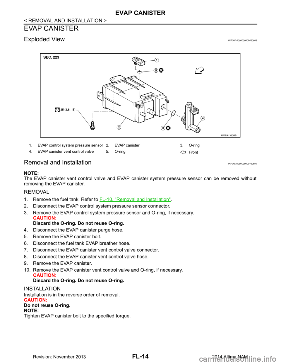
Exploded ViewINFOID:0000000009460608
Removal and InstallationINFOID:0000000009460609
NOTE:
The EVAP canister vent control valve and EVAP cani ster system pressure sensor can be removed without
removing the EVAP canister.
REMOVAL
1. Remove the fuel tank. Refer to FL-10, "Removal and Installation".
2. Disconnect the EVAP control system pressure sensor connector.
3. Remove the EVAP control system pressu re sensor and O-ring, if necessary.
CAUTION:
Discard the O-ring. Do not reuse O-ring.
4. Disconnect the EVAP canister purge hose.
5. Remove the EVAP canister bolt.
6. Disconnect the fuel tank EVAP breather hose.
7. Disconnect the EVAP canister vent control valve connector.
8. Disconnect the EVAP canister vent control valve hose.
9. Remove the EVAP canister.
10. Remove the EVAP canister vent c ontrol valve and O-ring, if necessary.
CAUTION:
Discard the O-ring. Do not reuse O-ring.
INSTALLATION
Installation is in the reverse order of removal.
CAUTION:
Do not reuse O-ring.
NOTE:
Tighten EVAP canister bolt to the specified torque.
1. EVAP control system pressure sensor 2. EVAP canister 3. O-ring
4. EVAP canister vent control valve 5. O-ring Front
AWBIA1320GB
Revision: November 20132014 Altima NAM
Page 2557 of 4801
PRECAUTIONSGI-29
< PRECAUTION >
C
D E
F
G H
I
J
K L
M B
GI
N
O P
To prevent ECM from storing the diagnostic trou ble codes, do not carelessly disconnect the harness
connectors which are related to the engine cont rol system and TCM (transmission control module)
system. The connectors should be disconnected only when working according to the WORK FLOW of
TROUBLE DIAGNOSES in EC and TM sections.
Three Way CatalystINFOID:0000000009462996
If a large amount of unburned fuel flows into the catalyst , the catalyst temperature will be excessively high. To
prevent this, follow the instructions.
• Use unleaded gasoline only. Leaded gasoline will seriously damage the three way catalyst.
• When checking for ignition spark or measuring engine compression, make tests quickly and only when nec- essary.
• Do not run engine when the fuel tank level is low, otherwise the engine may misfire, causing damage to the
catalyst.
Do not place the vehicle on flammable material. Keep flammable material off the exhaust pipe and the three
way catalyst.
Fuel (Regular Unleaded Ga soline Recommended) QR25DEINFOID:0000000009462997
Use unleaded regular gasoline with an octane rating of at least 87 AKI (Anti-Knock Index) number (Research
octane number 91). E-85 fuel (85% fuel ethanol, 15% unl eaded gasoline) may only be used in vehicles specif-
ically designed for E-85 fuel (i.e. Flexible Fuel Vehicle - FFV models).
CAUTION:
Do not use leaded gasoli ne. Using leaded gasoline will damage the three way catalyst. Do not use E-85
fuel (85% fuel ethanol, 15% unlead ed gasoline) unless the vehicle is specifically designed for E-85 fuel
(i.e. Flexible Fuel Vehicle - FFV models). Using a fu el other than that specified could adversely affect
the emission control devices and systems, and could also affect the warranty coverage validity.
Fuel (Regular Unleaded Gasoline Recommended) VQ35DEINFOID:0000000009462998
Use unleaded regular gasoline with an octane rating of at least 87 AKI (Anti-Knock Index) number (Research
octane number 91). E-85 fuel (85% fuel ethanol, 15% unl eaded gasoline) may only be used in vehicles specif-
ically designed for E-85 fuel (i.e. Flexible Fuel Vehicle - FFV models).
CAUTION:
Do not use leaded gasoli ne. Using leaded gasoline will damage the three way catalyst. Do not use E-85
fuel (85% fuel ethanol, 15% unlead ed gasoline) unless the vehicle is specifically designed for E-85 fuel
(i.e. Flexible Fuel Vehicle - FFV models). Using a fu el other than that specified could adversely affect
the emission control devices and systems, and could also affect the warranty coverage validity.
Multiport Fuel Injection System or Engine Control SystemINFOID:0000000009462999
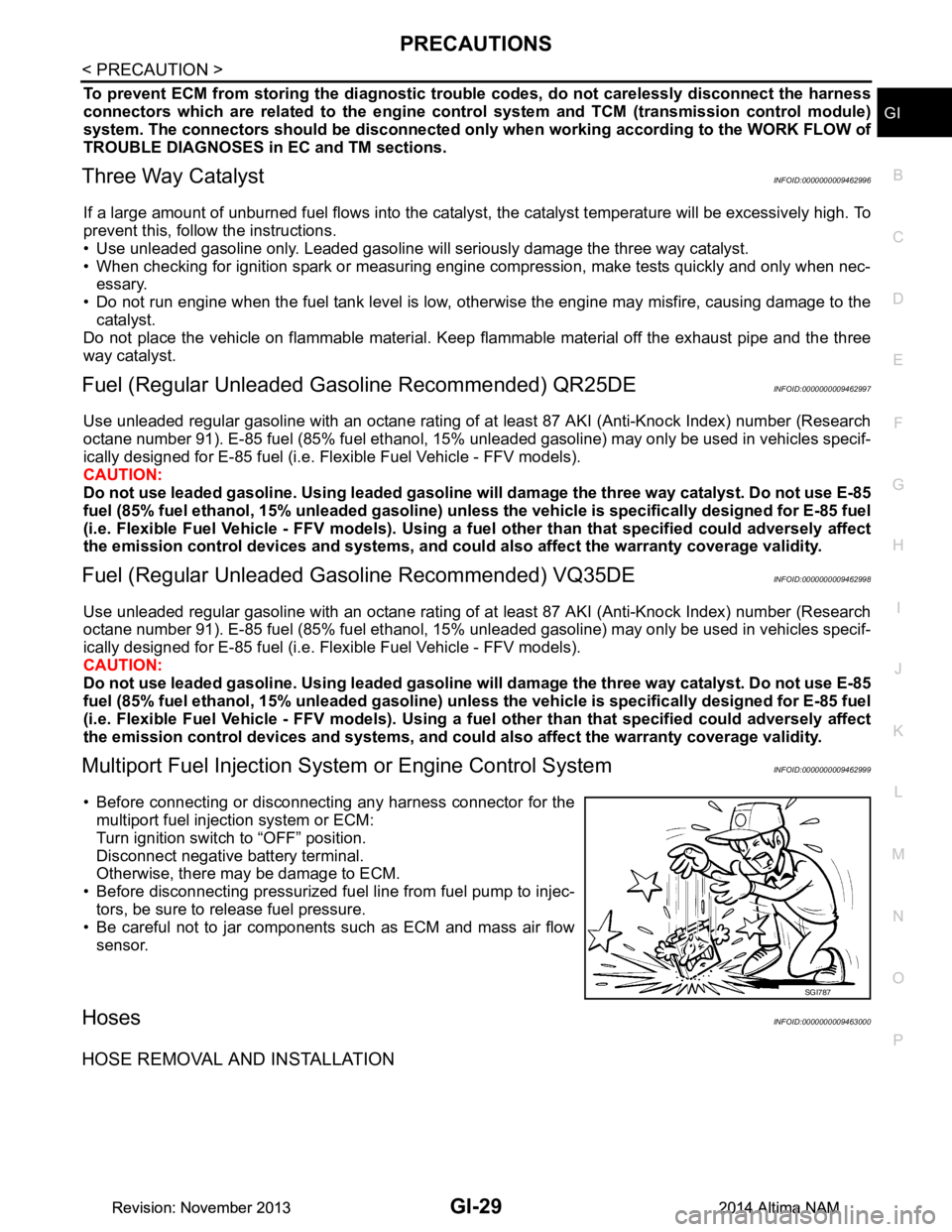
• Before connecting or disconnecti ng any harness connector for the
multiport fuel injection system or ECM:
Turn ignition switch to “OFF” position.
Disconnect negative battery terminal.
Otherwise, there may be damage to ECM.
• Before disconnecting pressurized fuel line from fuel pump to injec-
tors, be sure to release fuel pressure.
• Be careful not to jar components such as ECM and mass air flow sensor.
HosesINFOID:0000000009463000
HOSE REMOVAL AND INSTALLATION
SGI787
Revision: November 20132014 Altima NAMRevision: November 20132014 Altima NAM
Page 3200 of 4801
MA-16
< PERIODIC MAINTENANCE >
ENGINE MAINTENANCE (QR25DE)
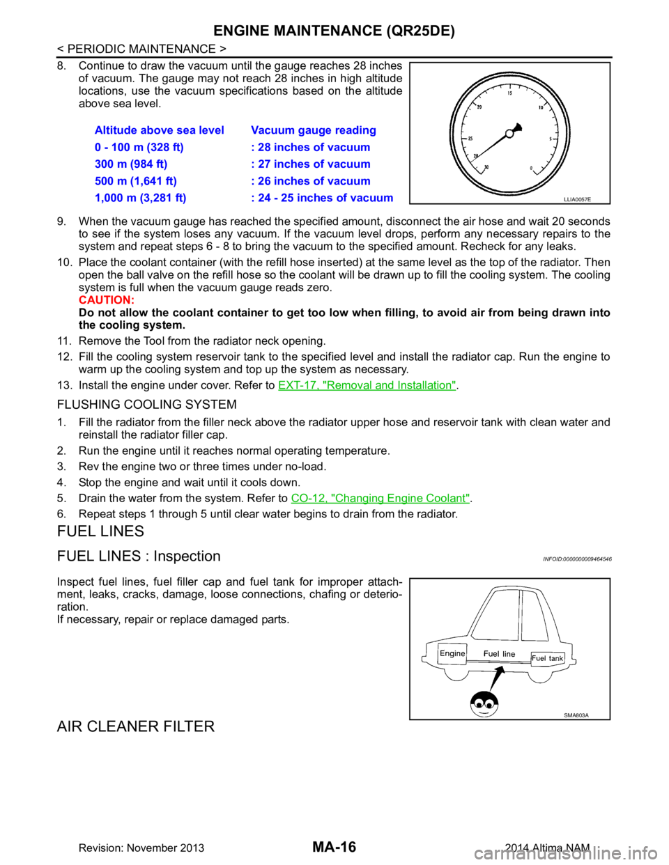
8. Continue to draw the vacuum until the gauge reaches 28 inchesof vacuum. The gauge may not reach 28 inches in high altitude
locations, use the vacuum specifications based on the altitude
above sea level.
9. When the vacuum gauge has reached the specifi ed amount, disconnect the air hose and wait 20 seconds
to see if the system loses any vacuum. If the vacuum level drops, perform any necessary repairs to the
system and repeat steps 6 - 8 to bring the vacuum to the specified amount. Recheck for any leaks.
10. Place the coolant container (with the refill hose insert ed) at the same level as the top of the radiator. Then
open the ball valve on the refill hose so the coolant will be drawn up to fill the cooling system. The cooling
system is full when the vacuum gauge reads zero.
CAUTION:
Do not allow the coolant container to get too low when filling, to avoid air from being drawn into
the cooling system.
11. Remove the Tool from the radiator neck opening.
12. Fill the cooling system reservoir tank to the specif ied level and install the radiator cap. Run the engine to
warm up the cooling system and t op up the system as necessary.
13. Install the engine under cover. Refer to EXT-17, "Removal and Installation"
.
FLUSHING COOLING SYSTEM
1. Fill the radiator from the filler neck above the radiator upper hose and reservoir tank with clean water and
reinstall the radiator filler cap.
2. Run the engine until it reaches normal operating temperature.
3. Rev the engine two or three times under no-load.
4. Stop the engine and wait until it cools down.
5. Drain the water from the system. Refer to CO-12, "Changing Engine Coolant"
.
6. Repeat steps 1 through 5 until clear water begins to drain from the radiator.
FUEL LINES
FUEL LINES : InspectionINFOID:0000000009464546
Inspect fuel lines, fuel filler cap and fuel tank for improper attach-
ment, leaks, cracks, damage, loose connections, chafing or deterio-
ration.
If necessary, repair or replace damaged parts.
AIR CLEANER FILTER
Altitude above sea level Vacuum gauge reading
0 - 100 m (328 ft) : 28 inches of vacuum
300 m (984 ft) : 27 inches of vacuum
500 m (1,641 ft) : 26 inches of vacuum
1,000 m (3,281 ft) : 24 - 25 inches of vacuum
LLIA0057E
SMA803A
Revision: November 20132014 Altima NAM
Page 3205 of 4801
ENGINE MAINTENANCE (QR25DE)MA-21
< PERIODIC MAINTENANCE >
C
D E
F
G H
I
J
K L
M B
MA
N
O A
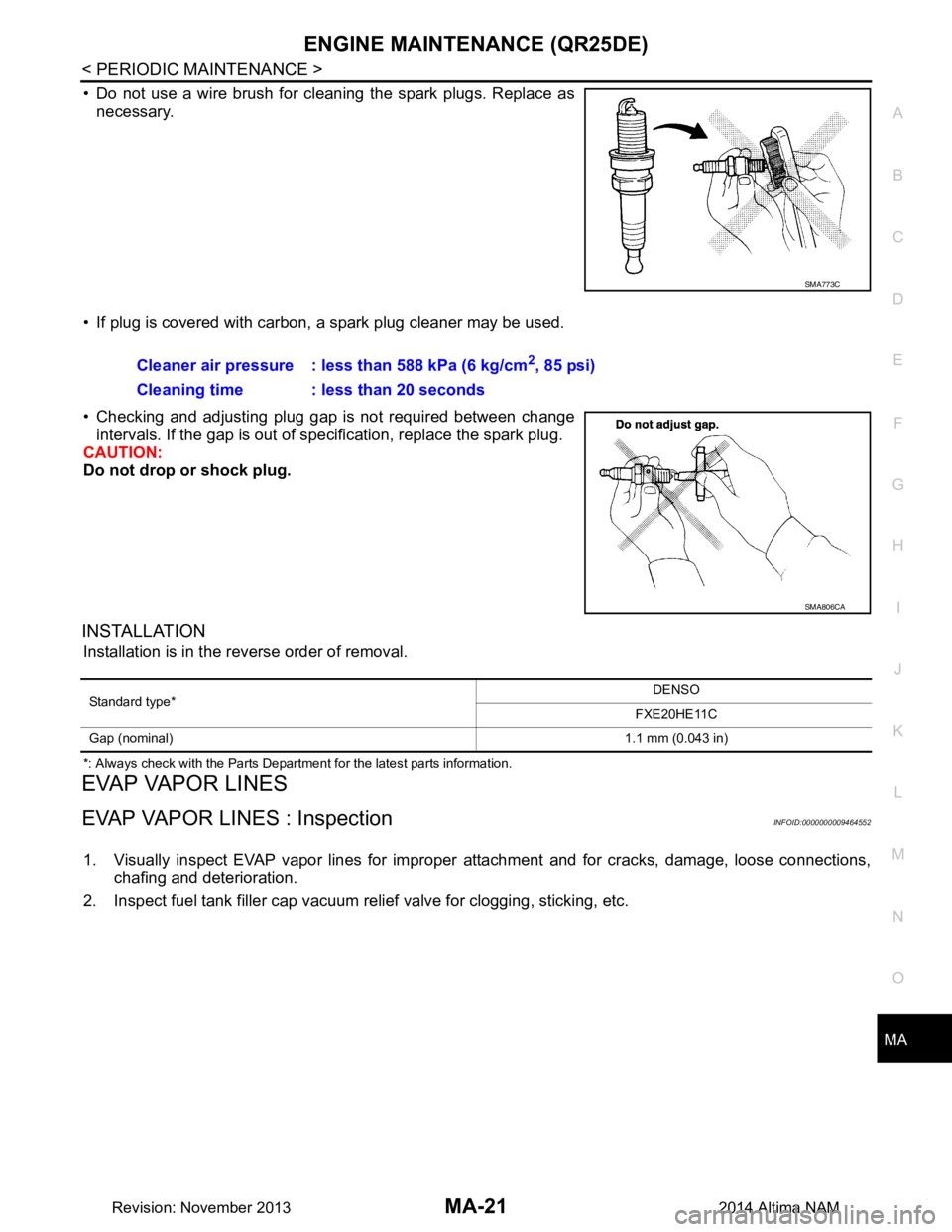
• Do not use a wire brush for cleaning the spark plugs. Replace as
necessary.
• If plug is covered with carbon, a spark plug cleaner may be used.
• Checking and adjusting plug gap is not required between change intervals. If the gap is out of s pecification, replace the spark plug.
CAUTION:
Do not drop or shock plug.
INSTALLATION
Installation is in the reverse order of removal.
*: Always check with the Parts Department for the latest parts information.
EVAP VAPOR LINES
EVAP VAPOR LINES : InspectionINFOID:0000000009464552
1. Visually inspect EVAP vapor lines for improper attachment and for cracks, damage, loose connections,
chafing and deterioration.
2. Inspect fuel tank filler cap vacuum relief valve for clogging, sticking, etc.
SMA773C
Cleaner air pressure : less than 588 kPa (6 kg/cm2, 85 psi)
Cleaning time : less than 20 seconds
SMA806CA
Standard type* DENSO
FXE20HE11C
Gap (nominal) 1.1 mm (0.043 in)
Revision: November 20132014 Altima NAM
Page 3209 of 4801
ENGINE MAINTENANCE (VQ35DE)MA-25
< PERIODIC MAINTENANCE >
C
D E
F
G H
I
J
K L
M B
MA
N
O A
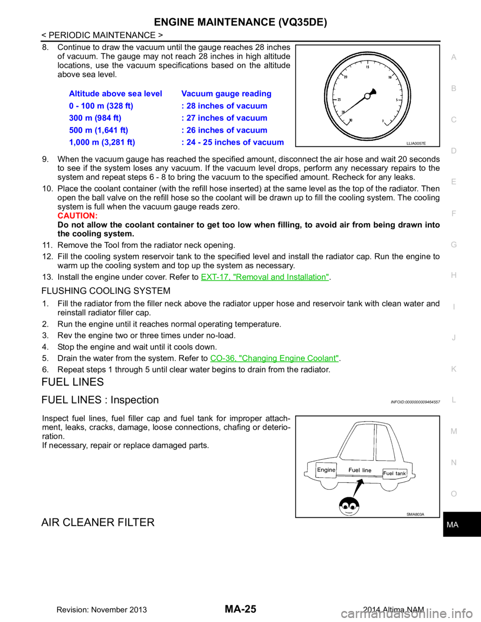
8. Continue to draw the vacuum until the gauge reaches 28 inches
of vacuum. The gauge may not reach 28 inches in high altitude
locations, use the vacuum specifications based on the altitude
above sea level.
9. When the vacuum gauge has reached the specified amount, disconnect the air hose and wait 20 seconds
to see if the system loses any vacuum. If the vacuum level drops, perform any necessary repairs to the
system and repeat steps 6 - 8 to br ing the vacuum to the specified amount. Recheck for any leaks.
10. Place the coolant container (with the refill hose inserted) at the same level as the top of the radiator. Then
open the ball valve on the refill hose so the coolant will be drawn up to fill the cooling system. The cooling
system is full when the vacuum gauge reads zero.
CAUTION:
Do not allow the coolant container to get too low when filling, to avoid air from being drawn into
the cooling system.
11. Remove the Tool from the radiator neck opening.
12. Fill the cooling system reservoir tank to the specif ied level and install the radiator cap. Run the engine to
warm up the cooling system and top up the system as necessary.
13. Install the engine under cover. Refer to EXT-17, "Removal and Installation"
.
FLUSHING COOLING SYSTEM
1. Fill the radiator from the filler neck above the r adiator upper hose and reservoir tank with clean water and
reinstall radiator filler cap.
2. Run the engine until it reaches normal operating temperature.
3. Rev the engine two or three times under no-load.
4. Stop the engine and wait until it cools down.
5. Drain the water from the system. Refer to CO-36, "Changing Engine Coolant"
.
6. Repeat steps 1 through 5 until clear water begins to drain from the radiator.
FUEL LINES
FUEL LINES : InspectionINFOID:0000000009464557
Inspect fuel lines, fuel filler cap and fuel tank for improper attach-
ment, leaks, cracks, damage, loos e connections, chafing or deterio-
ration.
If necessary, repair or replace damaged parts.
AIR CLEANER FILTER
Altitude above sea level Vacuum gauge reading
0 - 100 m (328 ft) : 28 inches of vacuum
300 m (984 ft) : 27 inches of vacuum
500 m (1,641 ft) : 26 inches of vacuum
1,000 m (3,281 ft) : 24 - 25 inches of vacuum
LLIA0057E
SMA803A
Revision: November 20132014 Altima NAM
Page 3214 of 4801
MA-30
< PERIODIC MAINTENANCE >
ENGINE MAINTENANCE (VQ35DE)
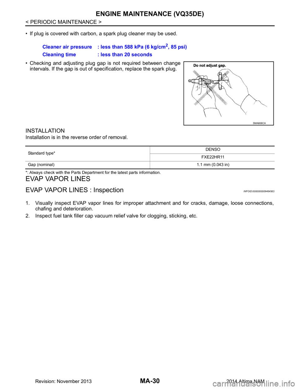
• If plug is covered with carbon, a spark plug cleaner may be used.
• Checking and adjusting plug gap is not required between change intervals. If the gap is out of s pecification, replace the spark plug.
INSTALLATION
Installation is in the reverse order of removal.
*: Always check with the Parts Department for the latest parts information.
EVAP VAPOR LINES
EVAP VAPOR LINES : InspectionINFOID:0000000009464563
1. Visually inspect EVAP vapor lines for improper attachment and for cracks, damage, loose connections,
chafing and deterioration.
2. Inspect fuel tank filler cap vacuum relief valve for clogging, sticking, etc. Cleaner air pressure : less than 588 kPa (6 kg/cm
2, 85 psi)
Cleaning time : less than 20 seconds
SMA806CA
Standard type* DENSO
FXE22HR11
Gap (nominal) 1.1 mm (0.043 in)
Revision: November 20132014 Altima NAM
Page 3316 of 4801
MWI
FUEL LEVEL SENSOR SIGNAL CIRCUITMWI-61
< DTC/CIRCUIT DIAGNOSIS >
C
D E
F
G H
I
J
K L
M B
A
O P
FUEL LEVEL SENSOR SIGNAL CIRCUIT
DescriptionINFOID:0000000009461718
The fuel level sensor unit and fuel pump detects the approx imate fuel level in the fuel tank and transmits the
fuel level signal to the combination meter.
Component Function CheckINFOID:0000000009461719
1.COMBINATION METER INPUT SIGNAL
1. Select METER/M&A on CONSULT.
2. Using FUEL METER of DATA MONITOR, compare the value of DATA MONITOR with fuel gauge pointer
of combination meter.
Does the data monitor value approxim ately match the fuel gauge indication?
YES >> Inspection End.
NO >> Replace combination meter. Refer to MWI-82, "Removal and Installation"
.
Diagnosis ProcedureINFOID:0000000009461720
Regarding Wiring Diagram information, refer to MWI-32, "Wiring Diagram".
1.CHECK HARNESS CONNECTOR
1. Turn ignition switch OFF.
2. Check combination meter and fuel level sensor uni t terminals (meter-side and harness-side) for poor con-
nection.
Is the inspection result normal?
YES >> GO TO 2.
NO >> Repair or replace terminals or connectors.
2.CHECK FUEL LEVEL SENSOR UNIT CIRCUIT
1. Disconnect combination meter harness connector M24 and fuel level sensor unit harness connector B42.
2. Check continuity between combination meter harne ss connector M24 and fuel level sensor unit and fuel
pump harness connector B42.
3. Check continuity between fuel level sens or unit and fuel pump harness connector and ground.
Is the inspection result normal?
YES >> GO TO 3.
Fuel gauge pointer Fuel tank volume [L]
(Approx.)
Full 67.6 3/4 52.6
1/2 37.6
1/4 22.5
Empty 0.0
Fuel level sensor unit and fuel pump Combination meter Continuity
Connector Terminal Connector Terminal
B42 5 M24 27 Yes
Connector Terminal GroundContinuity
B42 5 No
Revision: November 20132014 Altima NAMRevision: November 20132014 Altima NAM
Page 3317 of 4801
MWI-62
< DTC/CIRCUIT DIAGNOSIS >
FUEL LEVEL SENSOR SIGNAL CIRCUIT
NO >> Repair or replace harness or connectors.
3.CHECK FUEL LEVEL SENSOR UNIT GROUND CIRCUIT
1. Check continuity between combination meter harnes s connector M24 and fuel level sensor unit and fuel
pump harness connector B42.
2. Check continuity between fuel level sens or unit and fuel pump harness connector and ground.
Is the inspection result normal?
YES >> GO TO 4.
NO >> Repair or replace harness or connectors.
4.CHECK INSTALLATION CONDITION
Check fuel level sensor unit installation, and check whether the float arm interferes or binds with any of the
internal components in the fuel tank.
Is the inspection result normal?
YES >> Inspection End.
NO >> Install the fuel level sensor unit properly. Refer to FL-6, "Removal and Installation"
.
Component InspectionINFOID:0000000009461721
1.REMOVE FUEL LEVEL SENSOR UNIT
Remove the fuel level sensor unit. Refer to FL-6, "Removal and Installation"
.
>> GO TO 2
2.CHECK FUEL LEVEL SENSOR UNIT AND FUEL PUMP
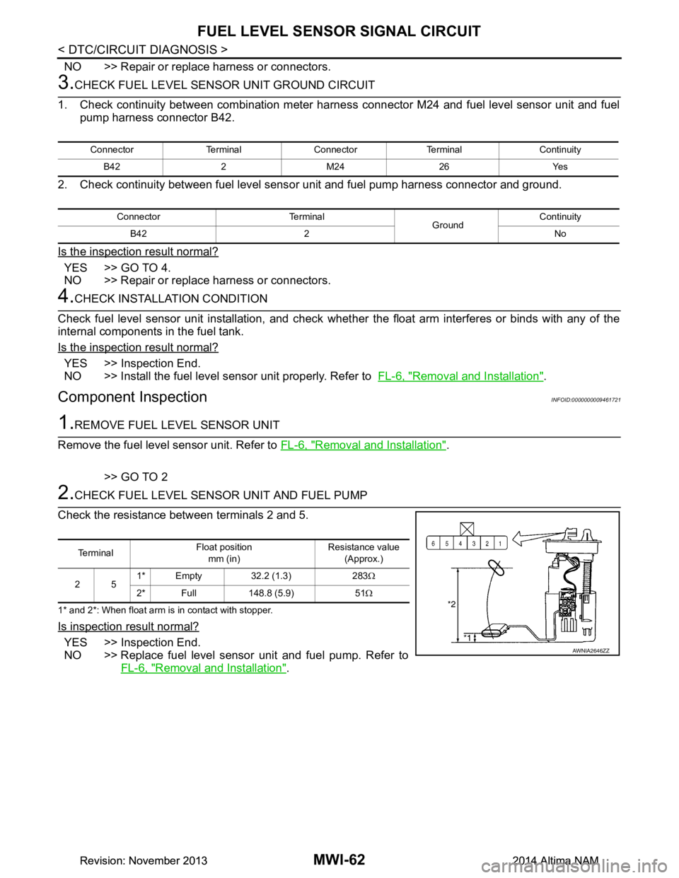
Check the resistance between terminals 2 and 5.
1* and 2*: When float arm is in contact with stopper.
Is inspection result normal?
YES >> Inspection End.
NO >> Replace fuel level sensor unit and fuel pump. Refer to FL-6, "Removal and Installation"
.
Connector Terminal Connector Terminal Continuity
B42 2 M24 26 Yes
Connector Terminal GroundContinuity
B42 2 No
Te r m i n a l Float position
mm (in) Resistance value
(Approx.)
25 1* Empty 32.2 (1.3) 283
Ω
2* Full 148.8 (5.9) 51 Ω
AWNIA2646ZZ
Revision: November 20132014 Altima NAMRevision: November 20132014 Altima NAM