2014 NISSAN TEANA wheel torque
[x] Cancel search: wheel torquePage 3663 of 4801
RAX-6
< REMOVAL AND INSTALLATION >
WHEEL HUB
REMOVAL AND INSTALLATION
WHEEL HUB
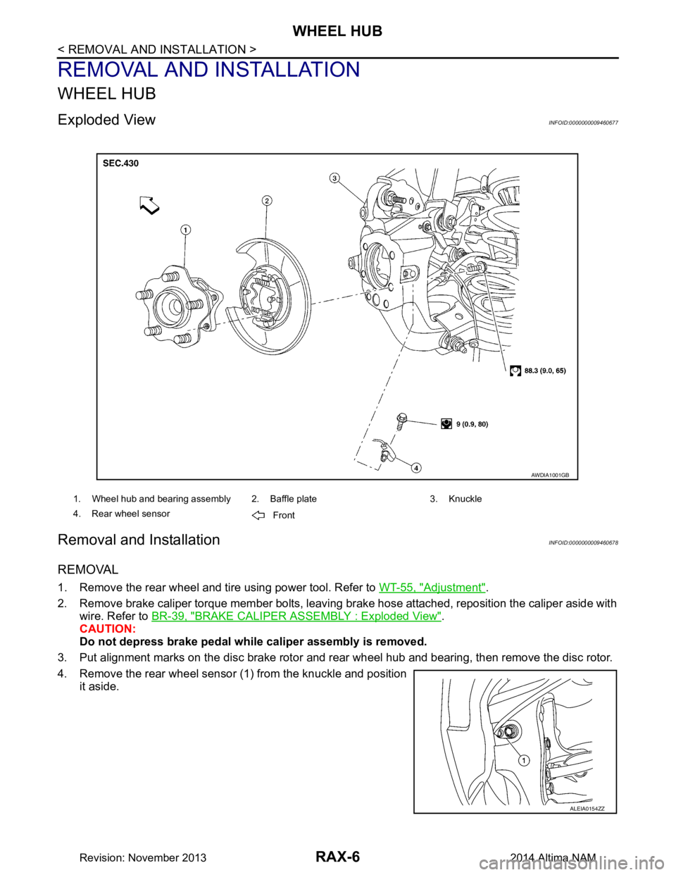
Exploded ViewINFOID:0000000009460677
Removal and InstallationINFOID:0000000009460678
REMOVAL
1. Remove the rear wheel and tire using power tool. Refer to WT-55, "Adjustment".
2. Remove brake caliper torque member bolts, leaving brake hose attached, reposition the caliper aside with
wire. Refer to BR-39, "BRAKE CALIPER AS SEMBLY : Exploded View"
.
CAUTION:
Do not depress brake pedal while caliper assembly is removed.
3. Put alignment marks on the disc brake rotor and rear wheel hub and bearing, then remove the disc rotor.
4. Remove the rear wheel sensor (1) from the knuckle and position
it aside.
1. Wheel hub and bearing assembly 2. Baffle plate 3. Knuckle
4. Rear wheel sensor Front
AWDIA1001GB
ALEIA0154ZZ
Revision: November 20132014 Altima NAM
Page 3722 of 4801
REAR SUSPENSION ASSEMBLYRSU-5
< PERIODIC MAINTENANCE >
C
D
F
G H
I
J
K L
M A
B
RSU
N
O P
PERIODIC MAINTENANCE
REAR SUSPENSION ASSEMBLY
On-vehicle ServiceINFOID:0000000009464454
• Check the suspension parts for excessive play, cracks, wear or damage. Shake each rear wheel to check for
excessive play.
• Retighten all nuts and bolts to the specified torque.
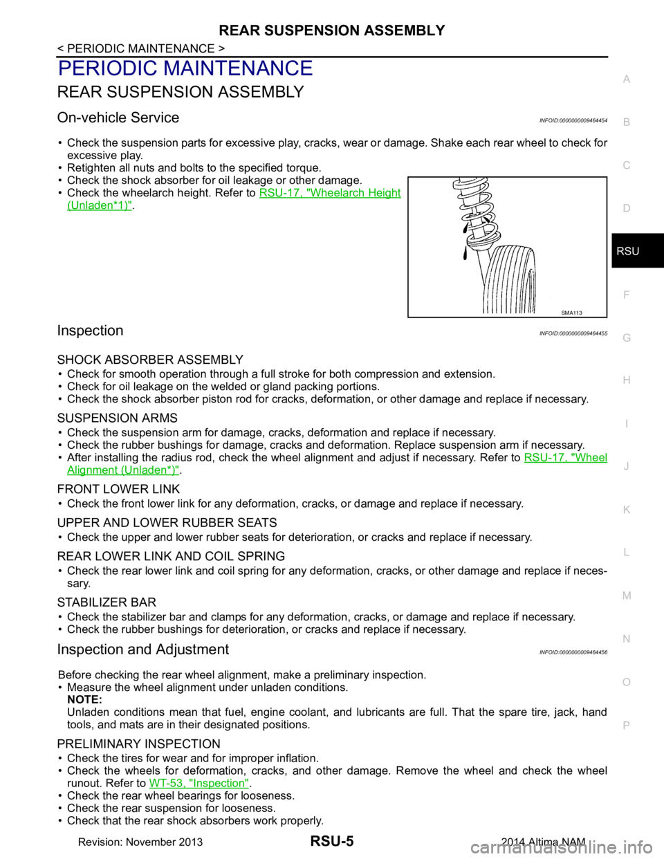
• Check the shock absorber for oil leakage or other damage.
• Check the wheelarch height. Refer to RSU-17, "Wheelarch Height
(Unladen*1)".
InspectionINFOID:0000000009464455
SHOCK ABSORBER ASSEMBLY
• Check for smooth operation through a full stroke for both compression and extension.
• Check for oil leakage on the welded or gland packing portions.
• Check the shock absorber piston r od for cracks, deformation, or other damage and replace if necessary.
SUSPENSION ARMS
• Check the suspension arm for damage, cracks, deformation and replace if necessary.
• Check the rubber bushings for damage, cracks and defo rmation. Replace suspension arm if necessary.
• After installing the radius rod, check the wheel alignment and adjust if necessary. Refer to RSU-17, "Wheel
Alignment (Unladen*)".
FRONT LOWER LINK
• Check the front lower link for any deformation, cracks, or damage and replace if necessary.
UPPER AND LOWER RUBBER SEATS
• Check the upper and lower rubber seats for deterioration, or cracks and replace if necessary.
REAR LOWER LINK AND COIL SPRING
• Check the rear lower link and coil spring for any def ormation, cracks, or other damage and replace if neces-
sary.
STABILIZER BAR
• Check the stabilizer bar and clamps for any deformation, cracks, or damage and replace if necessary.
• Check the rubber bushings for deterioration, or cracks and replace if necessary.
Inspection and AdjustmentINFOID:0000000009464456
Before checking the rear wheel ali gnment, make a preliminary inspection.
• Measure the wheel alignment under unladen conditions. NOTE:
Unladen conditions mean that fuel, engine coolant, and l ubricants are full. That the spare tire, jack, hand
tools, and mats are in their designated positions.
PRELIMINARY INSPECTION
• Check the tires for wear and for improper inflation.
• Check the wheels for deformation, cracks, and ot her damage. Remove the wheel and check the wheel
runout. Refer to WT-53, "Inspection"
.
• Check the rear wheel bearings for looseness.
• Check the rear suspension for looseness.
• Check that the rear shock absorbers work properly.
SMA113
Revision: November 20132014 Altima NAM
Page 3724 of 4801
REAR SUSPENSION ASSEMBLYRSU-7
< PERIODIC MAINTENANCE >
C
D
F
G H
I
J
K L
M A
B
RSU
N
O P
NOTE:
• Camber changes about 0 ° 5’ (0.08 °) with each graduation of the adjusting bolt.
• Turn the adjusting bolts in the same direction to calibrate camber.
• Toe changes about 1.5 mm (0.059 in) [one side] with each graduation of the adjusting bolt.
• Turn the adjusting bolts in the opposite direction to calibrate toe.
4. Tighten the adjusting bolt nuts to the specified torque. Camber : Refer to
RSU-17, "Wheel Alignment (Unlad-
en*)".
Total toe-in : Refer to RSU-17, "Wheel Alignment (Unlad-
en*)".
Adjusting bolt nuts : Refer to RSU-8, "Exploded View"
.
Revision: November 20132014 Altima NAM
Page 3964 of 4801

SR-2
< PRECAUTION >
PRECAUTIONS
PRECAUTION
PRECAUTIONS
Precaution for Supplemental Restraint System (SRS) "AIR BAG" and "SEAT BELT
PRE-TENSIONER"
INFOID:0000000009951759
The Supplemental Restraint System such as “A IR BAG” and “SEAT BELT PRE-TENSIONER”, used along
with a front seat belt, helps to reduce the risk or severi ty of injury to the driver and front passenger for certain
types of collision. Information necessary to service the system safely is included in the SR and SB section of
this Service Manual.
WARNING:
• To avoid rendering the SRS inopera tive, which could increase the risk of personal injury or death in
the event of a collision which would result in air bag inflation, all maintenance must be performed by
an authorized NISS AN/INFINITI dealer.
• Improper maintenance, including in correct removal and installation of the SRS, can lead to personal
injury caused by unintent ional activation of the system. For re moval of Spiral Cable and Air Bag
Module, see the SR section.
• Do not use electrical test equipmen t on any circuit related to the SRS unless instructed to in this
Service Manual. SRS wiring harn esses can be identified by yellow and/or orange harnesses or har-
ness connectors.
PRECAUTIONS WHEN USING POWER TOOLS (AIR OR ELECTRIC) AND HAMMERS
WARNING:
• When working near the Airbag Diagnosis Sensor Unit or other Airbag System sensors with the Igni-
tion ON or engine running, DO NOT use air or electri c power tools or strike near the sensor(s) with a
hammer. Heavy vibration could activate the sensor( s) and deploy the air bag(s), possibly causing
serious injury.
• When using air or electric power tools or hammers , always switch the Ignition OFF, disconnect the
battery and wait at least three minutes before performing any service.
ServiceINFOID:0000000009463063
• Do not use electrical test equipment to check SRS ci rcuits unless instructed to in this Service Manual.
• Before servicing the SRS, turn ignition switch OFF, disconnect both battery cables and wait at least three
minutes.
For approximately three minutes after the cables are remo ved, it is still possible for the air bag and seat belt
pre-tensioner to deploy. Therefore, do not work on any SRS connectors or wires until at least three minutes
have passed.
• Diagnosis sensor unit must always be installed with their arrow marks “ ⇐” pointing towards the front of the
vehicle for proper operation. Also chec k diagnosis sensor unit for cracks, deformities or rust before installa-
tion and replace as required.
• The spiral cable must be aligned with the neutral position since its rotations are limited. Do not turn steering
wheel and column after removal of steering gear.
• Handle air bag module carefully. Always place driver and front passenger air bag modules with the pad side facing upward and seat mounted front side air bag m odule standing with the stud bolt side facing down.
• Conduct self-diagnosis to check entire SRS for proper function after replacing any components.
• After air bag inflates, the instrument panel assembly should be replaced if damaged.
• Always replace instrument panel pad following front passenger air bag deployment.
Precaution for WorkINFOID:0000000009463065
• When removing or disassembling each component, be careful not to damage or deform it. If a component may be subject to interference, be sure to protect it with a shop cloth.
• When removing (disengaging) components with a screwdriver or similar tool, be sure to wrap the component with a shop cloth or vinyl tape to protect it.
• Protect the removed parts with a s hop cloth and prevent them from being dropped.
• Replace a deformed or damaged clip.
• If a part is specified as a non-reusable part, always replace it with a new one.
• Be sure to tighten bolts and nuts securely to the specified torque.
• After installation is complete, be sure to check that each part works properly.
Revision: November 20132014 Altima NAM
Page 4108 of 4801
PREPARATIONST-5
< PREPARATION >
C
D E
F
H I
J
K L
M A
B
ST
N
O P
PREPARATION
PREPARATION
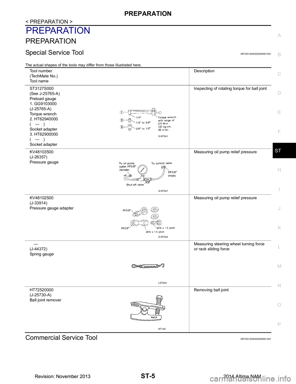
Special Service ToolINFOID:0000000009461242
The actual shapes of the tools may differ from those illustrated here.
Commercial Service ToolINFOID:0000000009461243
Tool number
(TechMate No.)
Tool name Description
ST3127S000
(See J-25765-A)
Preload gauge
1. GG9103000
(J-25765-A)
Torque wrench
2. HT62940000
(—)
Socket adapter
3. HT62900000
(—)
Socket adapter Inspecting of rotating torque for ball joint
KV48103500
(J-26357)
Pressure gauge Measuring oil pump relief pressure
KV48102500
(J-33914)
Pressure gauge adapter Measuring oil pump relief pressure
—
(J-44372)
Spring gauge Measuring steering wheel turning force
or rack sliding force
HT72520000
(J-25730-A)
Ball joint remover Removing ball joint
S-NT541
S-NT547
S-NT542
LST024
NT146
Revision: November 20132014 Altima NAMRevision: November 20132014 Altima NAM
Page 4132 of 4801
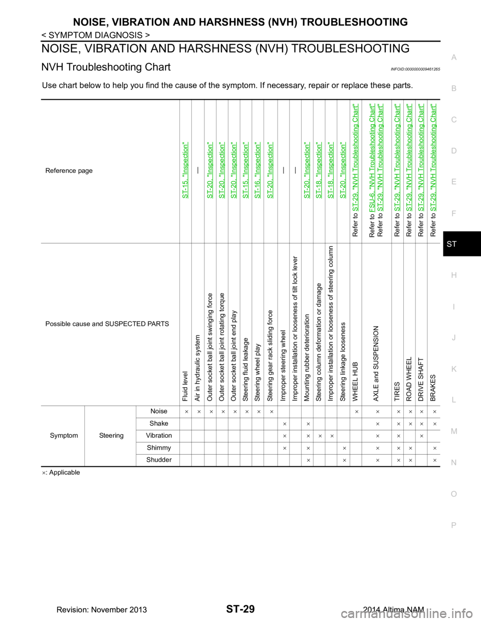
NOISE, VIBRATION AND HARSHNESS (NVH) TROUBLESHOOTINGST-29
< SYMPTOM DIAGNOSIS >
C
D E
F
H I
J
K L
M A
B
ST
N
O P
NOISE, VIBRATION AND HARSHN ESS (NVH) TROUBLESHOOTING
NVH Troubleshooting ChartINFOID:0000000009461265
Use chart below to help you find the cause of the symptom. If necessary, repair or replace these parts.
×: Applicable
Reference page
ST-15, "Inspection"
—
ST-20, "Inspection"
ST-20, "Inspection"ST-20, "Inspection"ST-15, "Inspection"ST-16, "Inspection"ST-20, "Inspection"
—
—
ST-20, "Inspection"
ST-18, "Inspection"ST-18, "Inspection"ST-20, "Inspection"
Refer to ST-29, "NVH Troubleshooting Chart"Refer to FSU-6, "NVH Troubleshooting Chart"
Refer to ST-29, "NVH Troubleshooting Chart"
Refer to ST-29, "NVH Troubleshooting Chart"
Refer to ST-29, "NVH Troubleshooting Chart"
Refer to ST-29, "NVH Troubleshooting Chart"
Refer to ST-29, "NVH Troubleshooting Chart"
Possible cause and SUSPECTED PARTS
Fluid level
Air in hydraulic system
Outer socket ball joint swinging force
Outer socket ball joint rotating torque
Outer socket ball joint end play
Steering fluid leakage
Steering wheel play
Steering gear rack sliding force
Improper steering wheel
Improper installation or looseness of tilt lock lever
Mounting rubber deterioration
Steering column deformation or damage
Improper installation or looseness of steering column
Steering linkage looseness
WHEEL HUB
AXLE and SUSPENSION
TIRES
ROAD WHEEL
DRIVE SHAFT
BRAKES
Symptom Steering Noise
× × ××××× × × × ××× ×
Shake ×× ×××××
Vibration × ××× × × ×
Shimmy ×× × ××× ×
Shudder ××××××
Revision: November 20132014 Altima NAMRevision: November 20132014 Altima NAM
Page 4153 of 4801

STC-2
Component Function Check ...................................31
Diagnosis Procedure ..............................................31
SYMPTOM DIAGNOSIS .............................32
HYDRAULIC PUMP ELECTRIC POWER
STEERING WARN ING LAMP DOES NOT
TURN ON ........................................................ ...
32
Description ........................................................... ...32
Diagnosis Procedure ..............................................32
HYDRAULIC PUMP ELECTRIC POWER
STEERING WARN ING LAMP DOES NOT
TURN OFF ...................................................... ...
33
Description ........................................................... ...33
Diagnosis Procedure ..............................................33
STEERING WHEEL TURNING FORCE IS
HEAVY OR LIGHT .......................................... ...
34
Diagnosis Procedure ............................................ ...34
UNBALANCE STEERING WHEEL TURNING
FORCE AND RETURN BETWEEN RIGHT
AND LEFT ...................................................... ...
36
Diagnosis Procedure ............................................ ...36
UNBALANCE STEERING WHEEL TURNING
FORCE (TORQUE VARIATION) .................... ...
37
Diagnosis Procedure ............................................ ...37
UNIT REMOVAL AND INSTALLATION ....39
POWER STEERING CONTROL MODULE .......39
Removal and Installation .........................................39
Revision: November 20132014 Altima NAMRevision: November 20132014 Altima NAM
Page 4188 of 4801
UNBALANCE STEERING WHEEL TURNING FORCE (TORQUE VARIATION)
STC-37
< SYMPTOM DIAGNOSIS >
C
D E
F
H I
J
K L
M A
B
STC
N
O P
UNBALANCE STEERING WHEEL TU RNING FORCE (TORQUE VARIA-
TION)
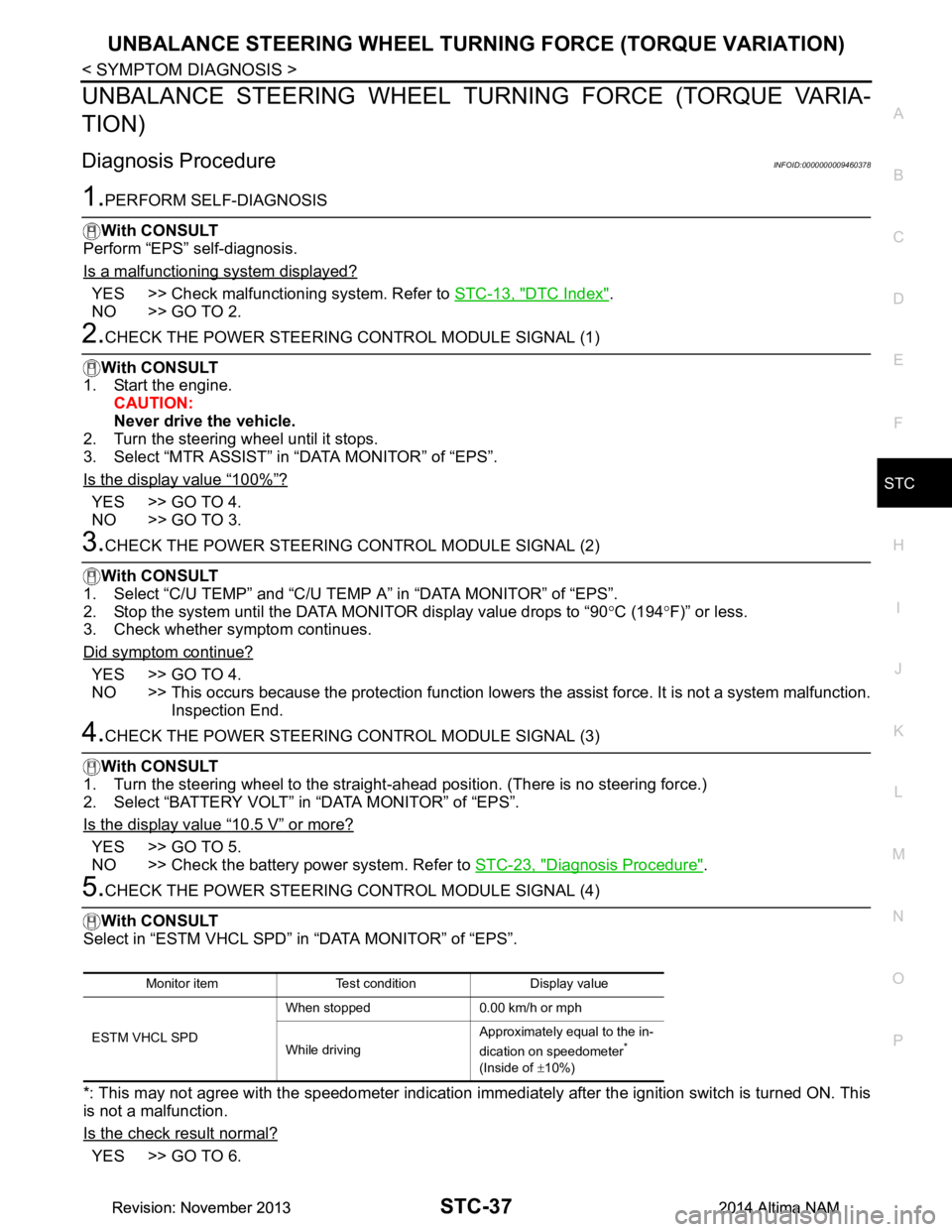
Diagnosis ProcedureINFOID:0000000009460378
1.PERFORM SELF-DIAGNOSIS
With CONSULT
Perform “EPS” self-diagnosis.
Is a malfunctioning system displayed?
YES >> Check malfunctioning system. Refer to STC-13, "DTC Index".
NO >> GO TO 2.
2.CHECK THE POWER STEERING CONTROL MODULE SIGNAL (1)
With CONSULT
1. Start the engine. CAUTION:
Never drive the vehicle.
2. Turn the steering wheel until it stops.
3. Select “MTR ASSIST” in “DATA MONITOR” of “EPS”.
Is the display value
“100%”?
YES >> GO TO 4.
NO >> GO TO 3.
3.CHECK THE POWER STEERING CONTROL MODULE SIGNAL (2)
With CONSULT
1. Select “C/U TEMP” and “C/U TEMP A” in “DATA MONITOR” of “EPS”.
2. Stop the system until the DATA MONITOR display value drops to “90 °C (194 °F)” or less.
3. Check whether symptom continues.
Did symptom continue?
YES >> GO TO 4.
NO >> This occurs because the protection function lowers the assist force. It is not a system malfunction.
Inspection End.
4.CHECK THE POWER STEERING CONTROL MODULE SIGNAL (3)
With CONSULT
1. Turn the steering wheel to the straight -ahead position. (There is no steering force.)
2. Select “BATTERY VOLT” in “DATA MONITOR” of “EPS”.
Is the display value
“10.5 V” or more?
YES >> GO TO 5.
NO >> Check the battery power system. Refer to STC-23, "Diagnosis Procedure"
.
5.CHECK THE POWER STEERING CONTROL MODULE SIGNAL (4)
With CONSULT
Select in “ESTM VHCL SPD” in “DATA MONITOR” of “EPS”.
*: This may not agree with the speedometer indication immediately after the ignition switch is turned ON. This
is not a malfunction.
Is the check result normal?
YES >> GO TO 6.
Monitor item Test condition Display value
ESTM VHCL SPD When stopped 0.00 km/h or mph
While driving Approximately equal to the in-
dication on speedometer
*
(Inside of ±10%)
Revision: November 20132014 Altima NAMRevision: November 20132014 Altima NAM