2014 NISSAN TEANA wheel bolt torque
[x] Cancel search: wheel bolt torquePage 2220 of 4801
![NISSAN TEANA 2014 Service Manual
EM-222
< UNIT REMOVAL AND INSTALLATION >[VQ35DE]
ENGINE ASSEMBLY
• (B): LH cylinder head
25. Remove rear cover plate.
26. Remove the torque converter nuts.
27. Remove nuts of stabilizer connectin NISSAN TEANA 2014 Service Manual
EM-222
< UNIT REMOVAL AND INSTALLATION >[VQ35DE]
ENGINE ASSEMBLY
• (B): LH cylinder head
25. Remove rear cover plate.
26. Remove the torque converter nuts.
27. Remove nuts of stabilizer connectin](/manual-img/5/57390/w960_57390-2219.png)
EM-222
< UNIT REMOVAL AND INSTALLATION >[VQ35DE]
ENGINE ASSEMBLY
• (B): LH cylinder head
25. Remove rear cover plate.
26. Remove the torque converter nuts.
27. Remove nuts of stabilizer connecting rods from struts. Refer to FSU-19, "Exploded View"
.
28. Remove front wheel speed sensors and position aside. Refer to BRC-124, "Removal and Installation -
Front Wheel Sensor".
29. Remove front brake rotors. Refer to BR-36, "BRAKE CALIPER ASSEMBLY : Removal and Installation"
.
30. Remove piston rod nut. Refer to FSU-19, "Exploded View"
.
31. Remove front drive shaft (LH/RH). Refer to FAX-10, "Removal and Installation (LH)"
and FAX-12,
"Removal and Installation (RH)".
32. Remove RH drive shaft center bearing bracket.
33. Remove lower steering column pinch bolt. Refer to ST-33, "Exploded View"
.
34. Remove three way catalyst (manifold) (bank 1) heat shield.
35. Disconnect front and rear engine mounting insulator vacuum hoses.
36. Remove front and rear engine mounting insulator nut.
37. Position a suitable support table under suspension member and engine assembly. TM-206, "Removal and
Installation"
38. Disconnect the engine mounting insulator (LH), upper torque rod, and engine mounting insulator (RH).
39. For additional safety, secure the engine in position with suitable tool.
40. Remove suspension member bolts. Refer to FSU-19, "Exploded View"
.
41. Carefully lower the engine, transaxle assembly and suspension member using Tool, avoiding interference
with the vehicle body.
CAUTION:
• Before and during this procedure, alw ays check if any harnesses are left connected.
• Avoid any damage to, or any oil/grease smearin g or spilling onto the engine mounting insula-
tors.
42. Remove the starter motor. Refer to STR-23, "VQ35DE : Removal and Installation"
.
43. Remove the crankshaft position sensor (POS).
44. Remove engine and transaxle harness.
45. Separate the engine and transaxle and mount the engine on a suitable engine stand.
INSTALLATION
Installation is in the reverse order of removal.
NOTE:
Tighten transmission bolts to specification. Refer to TM-206, "Removal and Installation"
.
INSPECTION AFTER INSTALLATION
• Before starting engine, check oil/fluid levels including engine coolant and engine oil. If less than required
quantity, fill to the specified level. Refer to MA-11, "FOR USA AND CANADA : Fluids and Lubricants"
.
• Use procedure below to check for fuel leakage.
• Turn ignition switch ON (with engine stopped). With fuel pressure applied to fuel piping, check for fuel leak-
age at connection points.
ALBIA0263GB
Tool number : KV101J0010 (J-47242)
Revision: November 20132014 Altima NAM
Page 2492 of 4801
FL-12
< REMOVAL AND INSTALLATION >
FUEL TANK
8. Remove rear wheel and tire using power tool. Refer to WT-55, "Adjustment".
9. Remove rear brake pads. Refer to BR-38, "BRAKE PAD : Removal and Installation"
.
10. Remove rear torque members and rear disc brake rotor.
11. Disconnect rear parking brake shoe, and remove rear cables from toggle lever. Refer to PB-9, "Removal
and Installation".
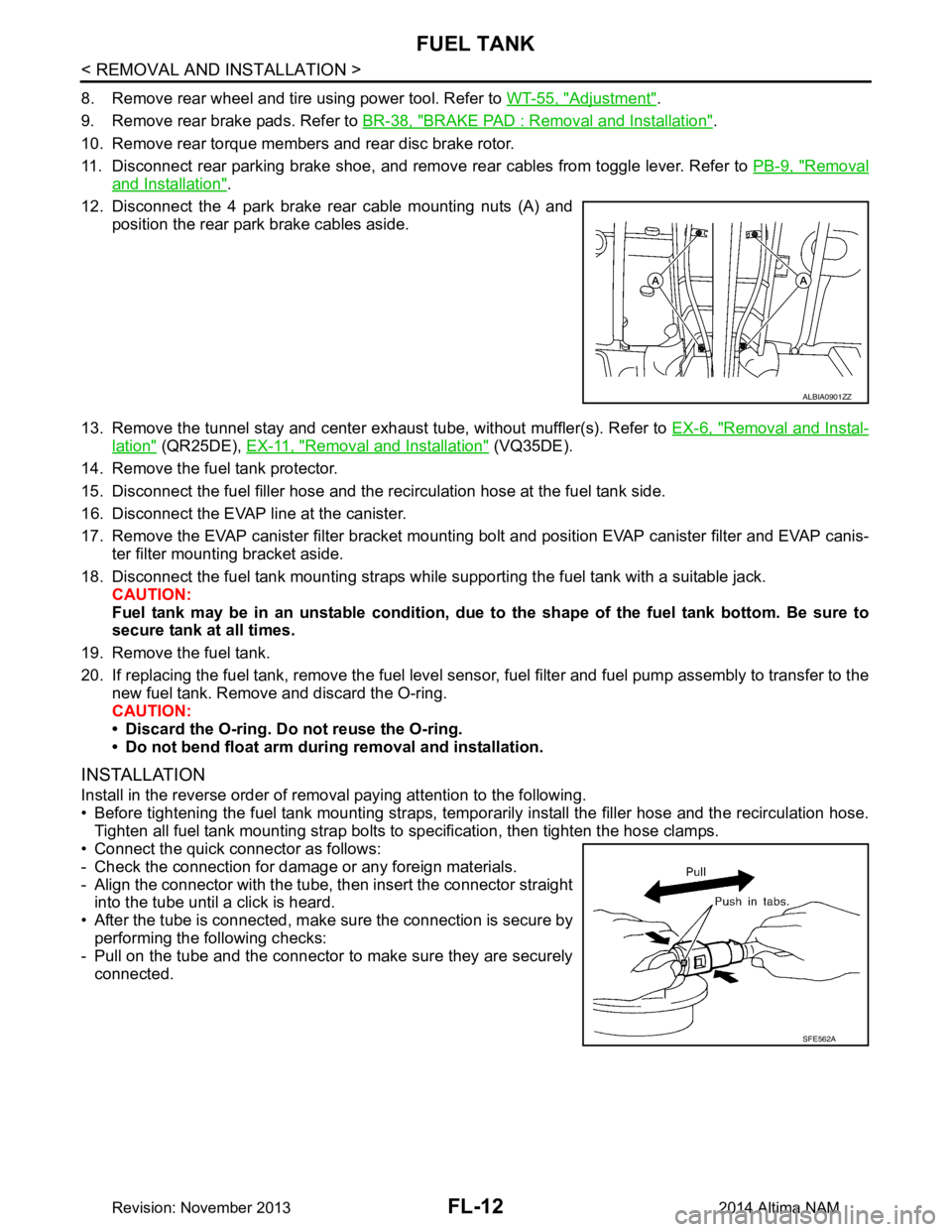
12. Disconnect the 4 park brake rear cable mounting nuts (A) and position the rear park brake cables aside.
13. Remove the tunnel stay and center exhaust tube, without muffler(s). Refer to EX-6, "Removal and Instal-
lation" (QR25DE), EX-11, "Removal and Installation" (VQ35DE).
14. Remove the fuel tank protector.
15. Disconnect the fuel filler hose and the recirculation hose at the fuel tank side.
16. Disconnect the EVAP line at the canister.
17. Remove the EVAP canister filter bracket mounti ng bolt and position EVAP canister filter and EVAP canis-
ter filter mounting bracket aside.
18. Disconnect the fuel tank mounting straps while supporting the fuel tank with a suitable jack. CAUTION:
Fuel tank may be in an unstable condition, due to the shape of the fuel tank bottom. Be sure to
secure tank at all times.
19. Remove the fuel tank.
20. If replacing the fuel tank, remove the fuel level sens or, fuel filter and fuel pump assembly to transfer to the
new fuel tank. Remove and discard the O-ring.
CAUTION:
• Discard the O-ring. Do not reuse the O-ring.
• Do not bend float arm during removal and installation.
INSTALLATION
Install in the reverse order of removal paying attention to the following.
• Before tightening the fuel tank mounting straps, tempor arily install the filler hose and the recirculation hose.
Tighten all fuel tank mounting strap bolts to specification, then tighten the hose clamps.
• Connect the quick connector as follows:
- Check the connection for damage or any foreign materials.
- Align the connector with the tube, then insert the connector straight into the tube until a click is heard.
• After the tube is connected, make sure the connection is secure by performing the following checks:
- Pull on the tube and the connector to make sure they are securely
connected.
ALBIA0901ZZ
SFE562A
Revision: November 20132014 Altima NAM
Page 2512 of 4801
TRANSVERSE LINKFSU-11
< REMOVAL AND INSTALLATION >
C
D
F
G H
I
J
K L
M A
B
FSU
N
O P
TRANSVERSE LINK
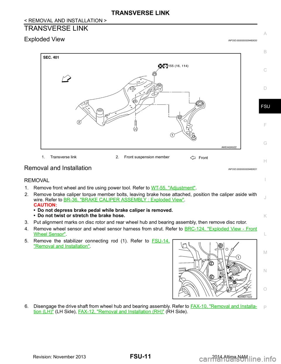
Exploded ViewINFOID:0000000009460630
Removal and InstallationINFOID:0000000009460631
REMOVAL
1. Remove front wheel and tire using power tool. Refer to WT-55, "Adjustment".
2. Remove brake caliper torque member bolts, leaving brake hose attached, position the caliper aside with
wire. Refer to BR-36, "BRAKE CALIPER ASSEMBLY : Exploded View"
.
CAUTION:
• Do not depress brake pedal while brake caliper is removed.
• Do not twist or stretch the brake hose.
3. Put alignment marks on disc rotor and rear wheel hub and bearing assembly, then remove disc rotor.
4. Remove wheel sensor and wheel sensor harness from strut. Refer to BRC-124, "Exploded View - Front
Wheel Sensor".
5. Remove the stabilizer connecting rod (1). Refer to FSU-14,
"Removal and Installation".
6. Disengage the drive shaft from wheel hub and bearing assembly. Refer to FAX-10, "Removal and Installa-
tion (LH)" (LH Side), FAX-12, "Removal and Installation (RH)" (RH Side).
1. Transverse link 2. Front suspension member
Front
AWEIA0263ZZ
ALEIA0172ZZ
Revision: November 20132014 Altima NAM
Page 2521 of 4801
FSU-20
< UNIT REMOVAL AND INSTALLATION >
FRONT SUSPENSION ASSEMBLY
Removal and Installation
INFOID:0000000009460637
QR25DE ENGINE
Removal
1. Remove front wheel and tire using power tool. Refer to WT-55, "Adjustment".
2. Remove each brake caliper using power tool, leaving brake caliper hydraulic hose attached. Position each brake caliper aside with wire. Refer to BR-36, "BRAKE CALIPER ASSEMBLY : Exploded View"
.
CAUTION:
• Do not depress brake pedal while brake caliper is removed.
• Do not twist or stretch the brake hose.
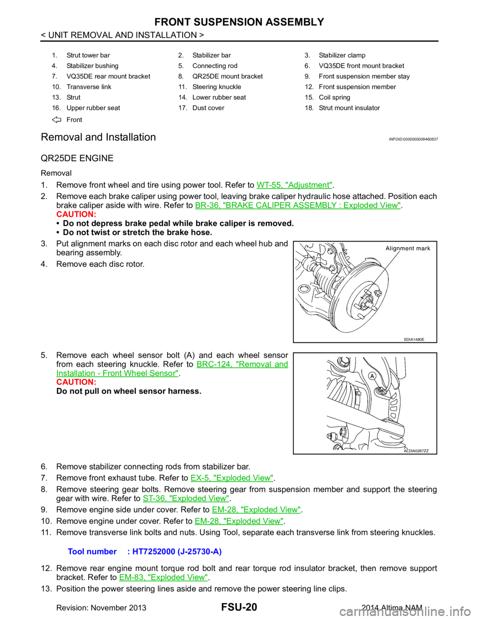
3. Put alignment marks on each disc rotor and each wheel hub and bearing assembly.
4. Remove each disc rotor.
5. Remove each wheel sensor bolt (A) and each wheel sensor from each steering knuckle. Refer to BRC-124, "Removal and
Installation - Front Wheel Sensor".
CAUTION:
Do not pull on wheel sensor harness.
6. Remove stabilizer connecting rods from stabilizer bar.
7. Remove front exhaust tube. Refer to EX-5, "Exploded View"
.
8. Remove steering gear bolts. Remove steering gear from suspension member and support the steering gear with wire. Refer to ST-36, "Exploded View"
.
9. Remove engine side under cover. Refer to EM-28, "Exploded View"
.
10. Remove engine under cover. Refer to EM-28, "Exploded View"
.
11. Remove transverse link bolts and nuts. Using Tool, separate each transverse link from steering knuckles.
12. Remove rear engine mount torque rod bolt and rear torque rod insulator bracket, then remove support bracket. Refer to EM-83, "Exploded View"
.
13. Position the power steering lines aside and remove the power steering line clips.
1. Strut tower bar 2. Stabilizer bar 3. Stabilizer clamp
4. Stabilizer bushing 5. Connecting rod 6. VQ35DE front mount bracket
7. VQ35DE rear mount bracket 8. QR25DE mount bracket 9. Front suspension member stay
10. Transverse link 11. Steering knuckle 12. Front suspension member
13. Strut 14. Lower rubber seat 15. Coil spring
16. Upper rubber seat 17. Dust cover 18. Strut mount insulator
Front
SDIA1480E
ALDIA0287ZZ
Tool number : HT7252000 (J-25730-A)
Revision: November 20132014 Altima NAM
Page 2529 of 4801
GI-1
GENERAL INFORMATION
C
D E
F
G H
I
J
K L
M B
GI
SECTION GI
N
O P
CONTENTS
GENERAL INFORMATION
HOW TO USE THIS MANU AL ......................3
HOW TO USE THIS MANUAL ....................... .....3
Description .......................................................... ......3
Terms ........................................................................3
Units ..........................................................................3
Contents ....................................................................3
Relation between Illustrations and Descriptions .......4
Components ..............................................................4
HOW TO FOLLOW TROUBLE DIAGNOSES .....6
Description ................................................................6
How to Follow Test Groups in Trouble Diagnosis ......6
Key to Symbols Signifying Measurements or Pro-
cedures ............................................................... ......
7
HOW TO READ WIRING DIAGRAMS ................9
Connector symbols ............................................. ......9
Sample/wiring diagram -example- ...........................10
Description ..............................................................11
ABBREVIATIONS .......................................... ....13
Abbreviation List .................................................. ....13
TIGHTENING TORQUE OF STANDARD
BOLTS ............................................................ ....
18
Description .......................................................... ....18
Tightening Torque Table (New Standard Includ-
ed) ....................................................................... ....
18
RECOMMENDED CHEMICAL PRODUCTS
AND SEALANTS ............................................ ....
21
Recommended Chemical Products and Sealants ....21
VEHICLE INFORMATION ............................22
IDENTIFICATION INFORMATION ................. ....22
Model Variation ................................................... ....22
Identification Number ..............................................23
Identification Plate ...................................................24
Engine Serial Number .............................................24
CVT Number ...........................................................25
Dimensions .......................................................... ....25
Wheels & Tires ........................................................25
PRECAUTION ..............................................26
PRECAUTIONS .................................................26
Description ........................................................... ....26
Precaution for Supplemental Restraint System
(SRS) "AIR BAG" and "SEAT BELT PRE-TEN-
SIONER" ............................................................. ....
26
Precautions For Xenon Headlamp Service .............26
Procedures without Cowl Top Cover .......................27
Cautions in Removing Battery Terminal and AV
Control Unit .......................................................... ....
27
General Precautions ................................................27
Three Way Catalyst .................................................29
Fuel (Regular Unleaded Gasoline Recommend-
ed) QR25DE ........................................................ ....
29
Fuel (Regular Unleaded Gasoline Recommend-
ed) VQ35DE ........................................................ ....
29
Multiport Fuel Injection System or Engine Control
System ................................................................. ....
29
Hoses ......................................................................29
Engine Oils ..............................................................30
Air Conditioning .......................................................31
LIFTING POINT .................................................32
Special Service Tool ................................................32
Pantograph Jack ......................................................32
Garage Jack and Safety Stand ................................33
2-Pole Lift ................................................................34
Board-on Lift ............................................................35
TOW TRUCK TOWING .....................................36
Tow Truck Towing ...................................................36
Vehicle Recovery (Freeing a Stuck Vehicle) ...........36
WIRING DIAGRAM ......................................38
CONSULT CHECKING SYSTEM .....................38
Wiring Diagram .................................................... ....38
Revision: November 20132014 Altima NAMRevision: November 20132014 Altima NAM
Page 3663 of 4801
RAX-6
< REMOVAL AND INSTALLATION >
WHEEL HUB
REMOVAL AND INSTALLATION
WHEEL HUB
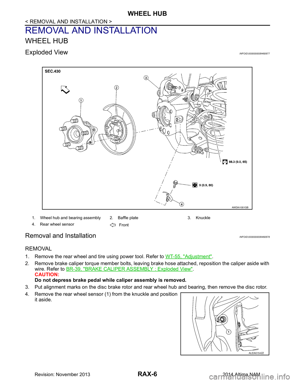
Exploded ViewINFOID:0000000009460677
Removal and InstallationINFOID:0000000009460678
REMOVAL
1. Remove the rear wheel and tire using power tool. Refer to WT-55, "Adjustment".
2. Remove brake caliper torque member bolts, leaving brake hose attached, reposition the caliper aside with
wire. Refer to BR-39, "BRAKE CALIPER AS SEMBLY : Exploded View"
.
CAUTION:
Do not depress brake pedal while caliper assembly is removed.
3. Put alignment marks on the disc brake rotor and rear wheel hub and bearing, then remove the disc rotor.
4. Remove the rear wheel sensor (1) from the knuckle and position
it aside.
1. Wheel hub and bearing assembly 2. Baffle plate 3. Knuckle
4. Rear wheel sensor Front
AWDIA1001GB
ALEIA0154ZZ
Revision: November 20132014 Altima NAM
Page 3722 of 4801
REAR SUSPENSION ASSEMBLYRSU-5
< PERIODIC MAINTENANCE >
C
D
F
G H
I
J
K L
M A
B
RSU
N
O P
PERIODIC MAINTENANCE
REAR SUSPENSION ASSEMBLY
On-vehicle ServiceINFOID:0000000009464454
• Check the suspension parts for excessive play, cracks, wear or damage. Shake each rear wheel to check for
excessive play.
• Retighten all nuts and bolts to the specified torque.
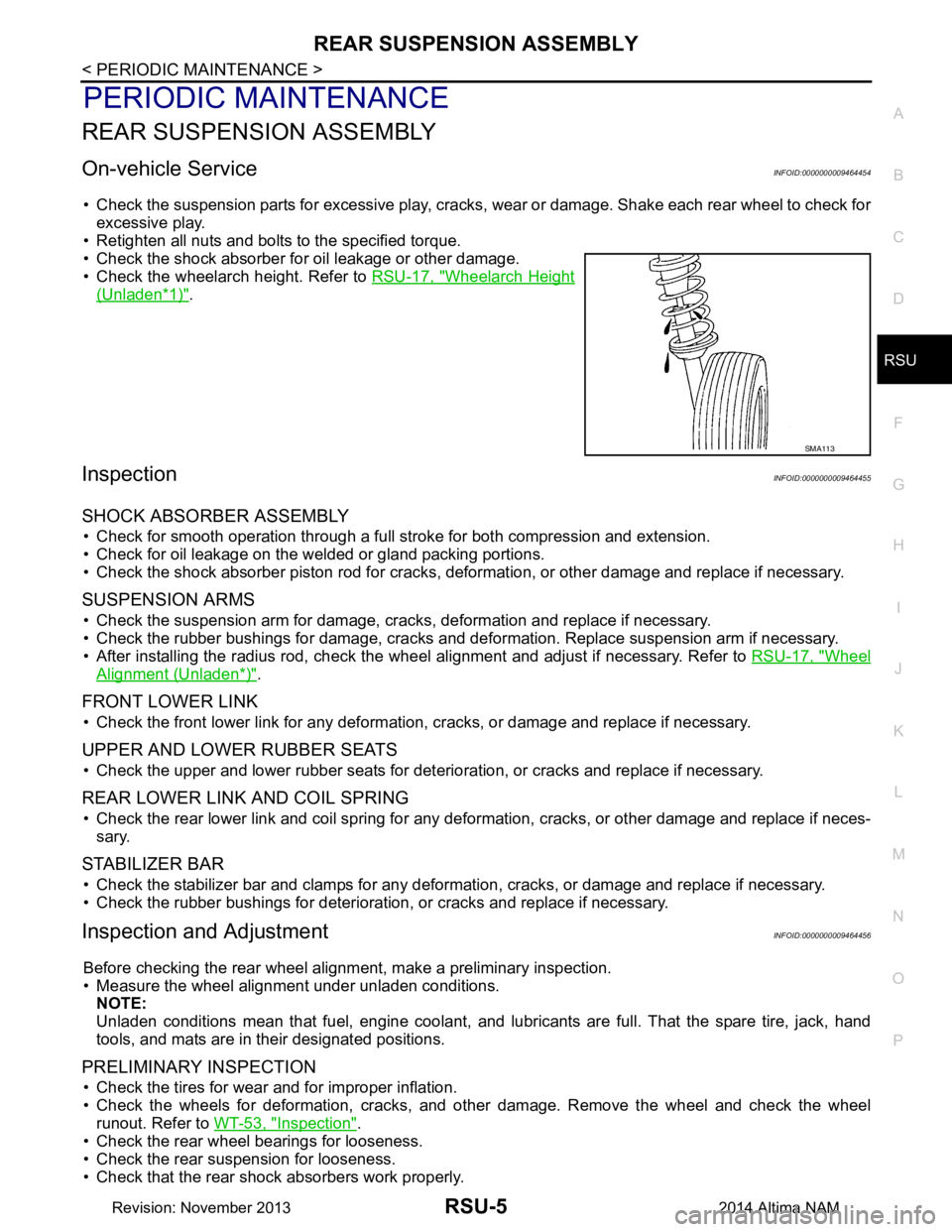
• Check the shock absorber for oil leakage or other damage.
• Check the wheelarch height. Refer to RSU-17, "Wheelarch Height
(Unladen*1)".
InspectionINFOID:0000000009464455
SHOCK ABSORBER ASSEMBLY
• Check for smooth operation through a full stroke for both compression and extension.
• Check for oil leakage on the welded or gland packing portions.
• Check the shock absorber piston r od for cracks, deformation, or other damage and replace if necessary.
SUSPENSION ARMS
• Check the suspension arm for damage, cracks, deformation and replace if necessary.
• Check the rubber bushings for damage, cracks and defo rmation. Replace suspension arm if necessary.
• After installing the radius rod, check the wheel alignment and adjust if necessary. Refer to RSU-17, "Wheel
Alignment (Unladen*)".
FRONT LOWER LINK
• Check the front lower link for any deformation, cracks, or damage and replace if necessary.
UPPER AND LOWER RUBBER SEATS
• Check the upper and lower rubber seats for deterioration, or cracks and replace if necessary.
REAR LOWER LINK AND COIL SPRING
• Check the rear lower link and coil spring for any def ormation, cracks, or other damage and replace if neces-
sary.
STABILIZER BAR
• Check the stabilizer bar and clamps for any deformation, cracks, or damage and replace if necessary.
• Check the rubber bushings for deterioration, or cracks and replace if necessary.
Inspection and AdjustmentINFOID:0000000009464456
Before checking the rear wheel ali gnment, make a preliminary inspection.
• Measure the wheel alignment under unladen conditions. NOTE:
Unladen conditions mean that fuel, engine coolant, and l ubricants are full. That the spare tire, jack, hand
tools, and mats are in their designated positions.
PRELIMINARY INSPECTION
• Check the tires for wear and for improper inflation.
• Check the wheels for deformation, cracks, and ot her damage. Remove the wheel and check the wheel
runout. Refer to WT-53, "Inspection"
.
• Check the rear wheel bearings for looseness.
• Check the rear suspension for looseness.
• Check that the rear shock absorbers work properly.
SMA113
Revision: November 20132014 Altima NAM
Page 3724 of 4801
REAR SUSPENSION ASSEMBLYRSU-7
< PERIODIC MAINTENANCE >
C
D
F
G H
I
J
K L
M A
B
RSU
N
O P
NOTE:
• Camber changes about 0 ° 5’ (0.08 °) with each graduation of the adjusting bolt.
• Turn the adjusting bolts in the same direction to calibrate camber.
• Toe changes about 1.5 mm (0.059 in) [one side] with each graduation of the adjusting bolt.
• Turn the adjusting bolts in the opposite direction to calibrate toe.
4. Tighten the adjusting bolt nuts to the specified torque. Camber : Refer to
RSU-17, "Wheel Alignment (Unlad-
en*)".
Total toe-in : Refer to RSU-17, "Wheel Alignment (Unlad-
en*)".
Adjusting bolt nuts : Refer to RSU-8, "Exploded View"
.
Revision: November 20132014 Altima NAM