2014 NISSAN TEANA battery replacement
[x] Cancel search: battery replacementPage 3984 of 4801

SR-22
< REMOVAL AND INSTALLATION >
CRASH ZONE SENSOR
CRASH ZONE SENSOR
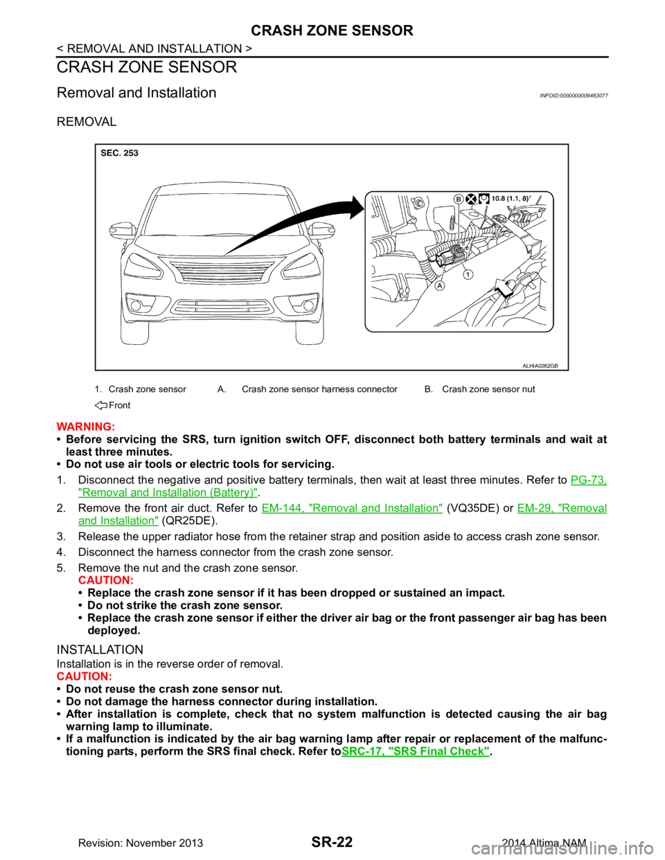
Removal and InstallationINFOID:0000000009463077
REMOVAL
WARNING:
• Before servicing the SRS, turn ig nition switch OFF, disconnect both battery terminals and wait at
least three minutes.
• Do not use air tools or el ectric tools for servicing.
1. Disconnect the negative and positive battery terminals, then wait at least three minutes. Refer to PG-73,
"Removal and Installation (Battery)".
2. Remove the front air duct. Refer to EM-144, "Removal and Installation"
(VQ35DE) or EM-29, "Removal
and Installation" (QR25DE).
3. Release the upper radiator hose from the retainer strap and position aside to access crash zone sensor.
4. Disconnect the harness connector from the crash zone sensor.
5. Remove the nut and the crash zone sensor. CAUTION:
• Replace the crash zone sensor if it has been dropped or sustained an impact.
• Do not strike the crash zone sensor.
• Replace the crash zone sensor if either the dri ver air bag or the front passenger air bag has been
deployed.
INSTALLATION
Installation is in the reverse order of removal.
CAUTION:
• Do not reuse the crash zone sensor nut.
• Do not damage the harness connector during installation.
• After installation is complete, check that no syst em malfunction is detected causing the air bag
warning lamp to illuminate.
• If a malfunction is indicated by the air bag warnin g lamp after repair or replacement of the malfunc-
tioning parts, perform the SRS final check. Refer to SRC-17, "SRS Final Check"
.
1. Crash zone sensor A. Crash zone sensor harness connector B. Crash zone sensor nut
Front
ALHIA0262GB
Revision: November 20132014 Altima NAM
Page 3986 of 4801

SR-24
< REMOVAL AND INSTALLATION >
SIDE AIR BAG (SATELLITE) SENSOR
1. Disconnect both the negative and positive battery terminals, then wait at least three minutes. Refer to PG-
73, "Removal and Installation (Battery)".
2. Remove front door finisher. Refer to INT-15, "Removal and Installation"
.
3. Disconnect the harness connector from the front door (satellite) sensor.
4. Remove the bolts and the front door (satellite) sensor. CAUTION:
• Do not reuse the front door satellite sensor bolts.
• Replace the front door satellite sensor if it has been dropped or sustained an impact.
• Do not strike the front door satellite sensor.
Installation
Installation is in the reverse order of removal.
CAUTION:
• Do not reuse the front door (satellite) sensor bolts.
• Do not damage the harness connector or harness.
• After installation is complete, check that no syst em malfunction is detected causing the air bag
warning lamp to illuminate.
• If a malfunction is indicated by the air bag warnin g lamp after repair or replacement of the malfunc-
tioning parts, perform the SRS final check. Refer to SRC-17, "SRS Final Check"
.
FRONT SIDE AIR BAG (SATELLITE) SENSOR (LH/RH)
Removal
1. Disconnect both the negative and positive battery terminal s, then wait at least three minutes. Refer to PG-
73, "Removal and Installation (Battery)".
2. Remove the front seat belt retractor. Refer to SB-8, "Removal and Installation"
.
3. Disconnect the harness connector from the front side air bag (satellite) sensor.
4. Remove the nut and the front side air bag (satellite) sensor. CAUTION:
• Do not reuse the front side air bag (satellite) sensor nut.
• Replace the front side air bag (satellite) sensor if it has been dropped or sustained an impact.
• Do not strike the front side air bag (satellite) sensor.
Installation
Installation is in the reverse order of removal.
CAUTION:
• Do not reuse the front side air bag (satellite) sensor nut.
• Do not damage the harness connector or harness.
• After installation is complete, check that no syst em malfunction is detected causing the air bag
warning lamp to illuminate.
• If a malfunction is indicated by the air bag warnin g lamp after repair or replacement of the malfunc-
tioning parts, perform the SRS final check. Refer to SRC-17, "SRS Final Check"
.
REAR SIDE AIR BAG (SATELLITE) SENSOR (LH/RH)
Removal
1. Disconnect both the negative and positive battery terminal s, then wait at least three minutes. Refer to PG-
73, "Removal and Installation (Battery)".
2. Remove the rear kicking plate inner. Refer to INT-22, "REAR KICKING PLATE : Removal and Installation
- Inner".
3. Disconnect the harness connector from the rear side air bag (satellite) sensor.
4. Remove the nut and the rear side air bag (satellite) sensor. CAUTION:
• Do not reuse the rear side air bag (satellite) sensor nut.
• Replace the rear side air bag (satellite) sensor if it has been dropped or sustained an impact.
• Do not strike the rear side air bag (satellite) sensor.
Installation
Installation is in the reverse order of removal.
CAUTION:
• Do not reuse the rear side air bag (satellite) sensor nut.
Revision: November 20132014 Altima NAM
Page 3990 of 4801

SR-28
< REMOVAL AND INSTALLATION >
OCCUPANT CLASSIFICATION SYSTEM
OCCUPANT CLASSIFICATION SYSTEM
Removal and InstallationINFOID:0000000009463081
OCCUPANT CLASSIFICATION SYSTEM CONTROL UNIT
WARNING:
• Before servicing the SRS, turn ig nition switch OFF, disconnect both battery terminals and wait at
least three minutes.
• Do not use air tools or el ectric tools for servicing.
Removal
1. Remove front passenger seat assembly. Refer to SE-30, "PASSENGER SIDE : Removal and Installation
- Seat Assembly".
2. Disconnect the harness connector from the oc cupant classification system control unit.
3. Remove occupant classification system control unit bolts.
4. Remove occupant classification system control unit. CAUTION:
• Replace the occupant classification control unit if it has been dropped or sustained an impact.
• Do not strike the occupant classification control unit.
Installation
Installation is in the reverse order of removal.
CAUTION:
• Do not damage the harness connector during installation.
• After installation is complete, check that no syst em malfunction is detected causing the air bag
warning lamp to illuminate.
• If a malfunction is indicated by the air bag warnin g lamp after repair or replacement of the malfunc-
tioning parts, perform the SRS final check. Refer to SRC-17, "SRS Final Check"
.
OCCUPANT CLASSIFICATION SYSTEM SENSORS
The occupant classification system sensors are part of the front passenger seat frame assembly. For disas-
sembly and assembly of the front passenger seat frame assembly. Refer to SE-55, "PASSENGER SIDE : Dis-
assembly and Assembly".
Revision: November 20132014 Altima NAM
Page 4190 of 4801

POWER STEERING CONTROL MODULESTC-39
< UNIT REMOVAL AND INSTALLATION >
C
D E
F
H I
J
K L
M A
B
STC
N
O P
UNIT REMOVAL AND INSTALLATION
POWER STEERING CONTROL MODULE
Removal and InstallationINFOID:0000000009460379
CAUTION:
Disconnect battery negative cable before removing the power steering pump assembly.
The power steering control module is an integral part of the power steering pump assembly. If replacement of
the power steering control module is necessary, replac e the complete power steering pump assembly. Refer
to ST-38, "Removal and Installation"
.
Revision: November 20132014 Altima NAMRevision: November 20132014 Altima NAM
Page 4224 of 4801
![NISSAN TEANA 2014 Service Manual
PRECAUTIONSTM-9
< PRECAUTION > [CVT: RE0F10D]
C
EF
G H
I
J
K L
M A
B
TM
N
O P
PRECAUTION
PRECAUTIONS
Precaution for Supplemental Restraint System (SRS) "AIR BAG" and "SEAT BELT
PRE-TENSIONER"
INFO NISSAN TEANA 2014 Service Manual
PRECAUTIONSTM-9
< PRECAUTION > [CVT: RE0F10D]
C
EF
G H
I
J
K L
M A
B
TM
N
O P
PRECAUTION
PRECAUTIONS
Precaution for Supplemental Restraint System (SRS) "AIR BAG" and "SEAT BELT
PRE-TENSIONER"
INFO](/manual-img/5/57390/w960_57390-4223.png)
PRECAUTIONSTM-9
< PRECAUTION > [CVT: RE0F10D]
C
EF
G H
I
J
K L
M A
B
TM
N
O P
PRECAUTION
PRECAUTIONS
Precaution for Supplemental Restraint System (SRS) "AIR BAG" and "SEAT BELT
PRE-TENSIONER"
INFOID:0000000009951696
The Supplemental Restraint System such as “A IR BAG” and “SEAT BELT PRE-TENSIONER”, used along
with a front seat belt, helps to reduce the risk or severi ty of injury to the driver and front passenger for certain
types of collision. Information necessary to service t he system safely is included in the SR and SB section of
this Service Manual.
WARNING:
• To avoid rendering the SRS inoper ative, which could increase the risk of personal injury or death in
the event of a collision which would result in air bag inflation, all maintenance must be performed by
an authorized NISSAN/INFINITI dealer.
• Improper maintenance, including in correct removal and installation of the SRS, can lead to personal
injury caused by unintentional act ivation of the system. For removal of Spiral Cable and Air Bag
Module, see the SR section.
• Do not use electrical test equipm ent on any circuit related to the SRS unless instructed to in this
Service Manual. SRS wiring harnesses can be identi fied by yellow and/or orange harnesses or har-
ness connectors.
PRECAUTIONS WHEN USING POWER TOOLS (AIR OR ELECTRIC) AND HAMMERS
WARNING:
• When working near the Airbag Diagnosis Sensor Un it or other Airbag System sensors with the Igni-
tion ON or engine running, DO NOT use air or el ectric power tools or strike near the sensor(s) with a
hammer. Heavy vibration could activate the sensor( s) and deploy the air bag(s), possibly causing
serious injury.
• When using air or electric power tools or hammers , always switch the Ignition OFF, disconnect the
battery and wait at least three mi nutes before performing any service.
Precaution for Procedure without Cowl Top CoverINFOID:0000000009463955
When performing the procedure after removing cowl top cover, cover
the lower end of windshield with urethane, etc to prevent damage to
windshield.
Precaution for TCM and Tran saxle Assembly ReplacementINFOID:0000000009463956
CAUTION:
• To replace TCM, refer to TM-80, "Description"
.
• To replace transaxle assembly, refer to TM-81, "Description"
.
PIIB3706J
Revision: November 20132014 Altima NAMRevision: November 20132014 Altima NAM
Page 4428 of 4801
![NISSAN TEANA 2014 Service Manual
PRECAUTIONSTM-213
< PRECAUTION > [CVT: RE0F10E]
C
EF
G H
I
J
K L
M A
B
TM
N
O P
PRECAUTION
PRECAUTIONS
Precaution for Supplemental Restraint System (SRS) "AIR BAG" and "SEAT BELT
PRE-TENSIONER"
IN NISSAN TEANA 2014 Service Manual
PRECAUTIONSTM-213
< PRECAUTION > [CVT: RE0F10E]
C
EF
G H
I
J
K L
M A
B
TM
N
O P
PRECAUTION
PRECAUTIONS
Precaution for Supplemental Restraint System (SRS) "AIR BAG" and "SEAT BELT
PRE-TENSIONER"
IN](/manual-img/5/57390/w960_57390-4427.png)
PRECAUTIONSTM-213
< PRECAUTION > [CVT: RE0F10E]
C
EF
G H
I
J
K L
M A
B
TM
N
O P
PRECAUTION
PRECAUTIONS
Precaution for Supplemental Restraint System (SRS) "AIR BAG" and "SEAT BELT
PRE-TENSIONER"
INFOID:0000000009951697
The Supplemental Restraint System such as “A IR BAG” and “SEAT BELT PRE-TENSIONER”, used along
with a front seat belt, helps to reduce the risk or severi ty of injury to the driver and front passenger for certain
types of collision. Information necessary to service t he system safely is included in the SR and SB section of
this Service Manual.
WARNING:
• To avoid rendering the SRS inoper ative, which could increase the risk of personal injury or death in
the event of a collision which would result in air bag inflation, all maintenance must be performed by
an authorized NISSAN/INFINITI dealer.
• Improper maintenance, including in correct removal and installation of the SRS, can lead to personal
injury caused by unintentional act ivation of the system. For removal of Spiral Cable and Air Bag
Module, see the SR section.
• Do not use electrical test equipm ent on any circuit related to the SRS unless instructed to in this
Service Manual. SRS wiring harnesses can be identi fied by yellow and/or orange harnesses or har-
ness connectors.
PRECAUTIONS WHEN USING POWER TOOLS (AIR OR ELECTRIC) AND HAMMERS
WARNING:
• When working near the Airbag Diagnosis Sensor Un it or other Airbag System sensors with the Igni-
tion ON or engine running, DO NOT use air or el ectric power tools or strike near the sensor(s) with a
hammer. Heavy vibration could activate the sensor( s) and deploy the air bag(s), possibly causing
serious injury.
• When using air or electric power tools or hammers , always switch the Ignition OFF, disconnect the
battery and wait at least three mi nutes before performing any service.
Precaution for Procedure without Cowl Top CoverINFOID:0000000009464173
When performing the procedure after removing cowl top cover, cover
the lower end of windshield with urethane, etc to prevent damage to
windshield.
Precaution for TCM and Tran saxle Assembly ReplacementINFOID:0000000009464174
CAUTION:
• To replace TCM, refer to TM-282, "Description"
.
• To replace transaxle assembly, refer to TM-283, "Description"
.
PIIB3706J
Revision: November 20132014 Altima NAMRevision: November 20132014 Altima NAM