2014 NISSAN TEANA air suspension
[x] Cancel search: air suspensionPage 2502 of 4801

FSU-1
SUSPENSION
C
D
F
G H
I
J
K L
M
SECTION FSU
A
B
FSU
N
O PCONTENTS
FRONT SUSPENSION
PRECAUTION ................ ...............................2
PRECAUTIONS .............................................. .....2
Precaution for Supplemental Restraint System
(SRS) "AIR BAG" and "SEAT BELT PRE-TEN-
SIONER" ............................................................. ......
2
General Precautions .................................................2
Precaution for Procedure without Cowl Top Cover ......2
Precautions for Suspension ......................................2
PREPARATION ............................................4
PREPARATION .............................................. .....4
Special Service Tool ........................................... ......4
Commercial Service Tool ..........................................5
SYMPTOM DIAGNOSIS ...............................6
NOISE, VIBRATION AND HARSHNESS
(NVH) TROUBLESHOOTING ........................ .....
6
NVH Troubleshooting Chart ................................ ......6
PERIODIC MAINTENANCE ..........................7
FRONT SUSPENSION ASSEMBLY .............. .....7
Inspection and Adjustment .................................. ......7
REMOVAL AND INSTALLATION ................9
FRONT COIL SPRING AND STRUT ............. .....9
Exploded View .................................................... ......9
Removal and Installation ...........................................9
Disposal .............................................................. ....10
TRANSVERSE LINK .........................................11
Exploded View ..................................................... ....11
Removal and Installation .........................................11
FRONT STABILIZER ........................................14
Exploded View .........................................................14
Removal and Installation .........................................14
STEERING KNUCKLE ......................................17
Exploded View .........................................................17
Removal and Installation .........................................17
UNIT REMOVAL AND INSTALLATION ......19
FRONT SUSPENSION ASSEMBLY .................19
Exploded View ..................................................... ....19
Removal and Installation .........................................20
UNIT DISASSEMBLY AND ASSEMBLY ....22
FRONT COIL SPRING AND STRUT ................22
Disassembly and Assembly ................................. ....22
SERVICE DATA AND SPECIFICATIONS
(SDS) ............... .............................................
25
SERVICE DATA AND SPECIFICATIONS
(SDS) .................................................................
25
Wheel Alignment (Unladen*1) ............................. ....25
Ball Joint ..................................................................26
Wheelarch Height (Unladen*1) ................................26
Revision: November 20132014 Altima NAM
Page 2503 of 4801
FSU-2
< PRECAUTION >
PRECAUTIONS
PRECAUTION
PRECAUTIONS
Precaution for Supplemental Restraint System (SRS) "AIR BAG" and "SEAT BELT
PRE-TENSIONER"
INFOID:0000000009951705
The Supplemental Restraint System such as “A IR BAG” and “SEAT BELT PRE-TENSIONER”, used along
with a front seat belt, helps to reduce the risk or severi ty of injury to the driver and front passenger for certain
types of collision. Information necessary to service the system safely is included in the SR and SB section of
this Service Manual.
WARNING:
• To avoid rendering the SRS inopera tive, which could increase the risk of personal injury or death in
the event of a collision which would result in air bag inflation, all maintenance must be performed by
an authorized NISS AN/INFINITI dealer.
• Improper maintenance, including in correct removal and installation of the SRS, can lead to personal
injury caused by unintent ional activation of the system. For re moval of Spiral Cable and Air Bag
Module, see the SR section.
• Do not use electrical test equipmen t on any circuit related to the SRS unless instructed to in this
Service Manual. SRS wiring harn esses can be identified by yellow and/or orange harnesses or har-
ness connectors.
PRECAUTIONS WHEN USING POWER TOOLS (AIR OR ELECTRIC) AND HAMMERS
WARNING:
• When working near the Airbag Diagnosis Sensor Unit or other Airbag System sensors with the Igni-
tion ON or engine running, DO NOT use air or electri c power tools or strike near the sensor(s) with a
hammer. Heavy vibration could activate the sensor( s) and deploy the air bag(s), possibly causing
serious injury.
• When using air or electric power tools or hammers , always switch the Ignition OFF, disconnect the
battery and wait at least three minutes before performing any service.
General PrecautionsINFOID:0000000009460620
• When installing rubber bushings, the final tightening mu st be carried out under unladen conditions with tires
on ground. Oil might shorten the life of rubber bushings. Be sure to wipe off any spilled oil.
- Unladen conditions mean that fuel, engine coolant and lubricant are full. Spare tire, jack, hand tools and mats are in designated positions.
• After servicing suspension parts, be sure to check wheel alignment.
• Self-lock nuts are not reusable. Always use new ones when installing. Since new self-lock nuts are pre-oiled,
tighten as they are.
Precaution for Procedure without Cowl Top CoverINFOID:0000000009460621
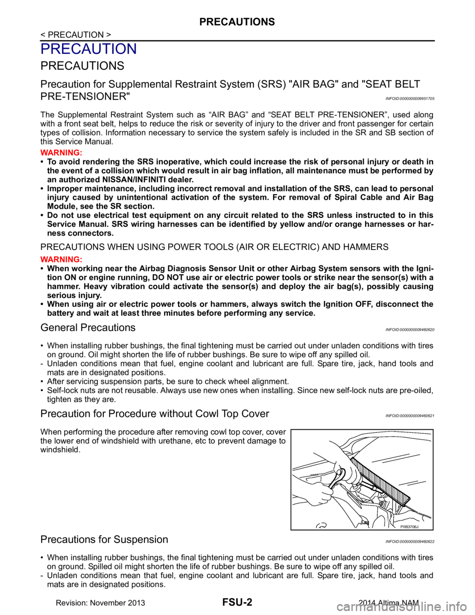
When performing the procedure after removing cowl top cover, cover
the lower end of windshield with urethane, etc to prevent damage to
windshield.
Precautions for SuspensionINFOID:0000000009460622
• When installing rubber bushings, the final tightening mu st be carried out under unladen conditions with tires
on ground. Spilled oil might shorten the life of rubber bushings. Be sure to wipe off any spilled oil.
- Unladen conditions mean that fuel, engine coolant and lubricant are full. Spare tire, jack, hand tools and mats are in designated positions.
PIIB3706J
Revision: November 20132014 Altima NAM
Page 2507 of 4801
FSU-6
< SYMPTOM DIAGNOSIS >
NOISE, VIBRATION AND HARSHNESS (NVH) TROUBLESHOOTING
SYMPTOM DIAGNOSIS
NOISE, VIBRATION AND HARSHNESS (NVH) TROUBLESHOOTING
NVH Troubleshooting ChartINFOID:0000000009460623
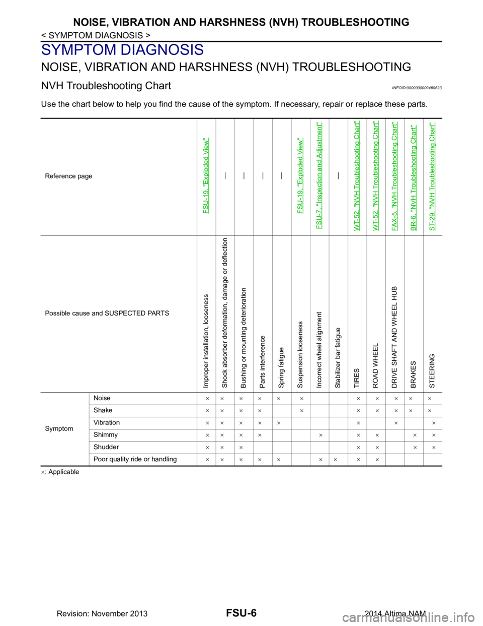
Use the chart below to help you find the cause of the sy mptom. If necessary, repair or replace these parts.
×: ApplicableReference page
FSU-19, "Exploded View"
—
—
—
—
FSU-19, "Exploded View"
FSU-7, "Inspection and Adjustment"
—
WT-52, "NVH Troubleshooting Chart"
WT-52, "NVH Troubleshooting Chart"FAX-5, "NVH Troubleshooting Chart"BR-6, "NVH Troubleshooting Chart"ST-29, "NVH Troubleshooting Chart"
Possible cause and SUSPECTED PARTS
Improper installation, looseness Shock absorber deformation, damage or deflection
Bushing or mounting deterioration
Parts interference
Spring fatigue
Suspension looseness
Incorrect wheel alignment
Stabilizer bar fatigue
TIRES
ROAD WHEEL
DRIVE SHAFT AND WHEEL HUB
BRAKES
STEERING
Symptom Noise
××××× × ×××××
Shake ×××× × ×××××
Vibration ×× × × × × × ×
Shimmy ×× × × × × × × ×
Shudder ×× × × × × ×
Poor quality ride or handling ×× × × × ×× × ×
Revision: November 20132014 Altima NAM
Page 2508 of 4801
FRONT SUSPENSION ASSEMBLYFSU-7
< PERIODIC MAINTENANCE >
C
D
F
G H
I
J
K L
M A
B
FSU
N
O P
PERIODIC MAINTENANCE
FRONT SUSPENSION ASSEMBLY
Inspection and AdjustmentINFOID:0000000009460626
INSPECTION
Make sure the mounting conditions (looseness, back lash) of each component and component conditions
(wear, damage) are normal.
LOWER BALL JOINT END PLAY
1. Set front wheels in a straight-ahead position. Do not depress brake pedal.
2. Place an iron bar or similar tool between upper link and steering knuckle.
3. Measure axial end play by prying it up and down.Refer to FSU-26, "Ball Joint"
.
CAUTION:
Be careful not to damage ball joint boot. Do not damage the installation position by applying
excessive force.
SHOCK ABSORBER
Check for oil leakage, damage and repl ace if malfunction is detected.
WHEEL ALIGNMENT
Description
Measure wheel alignment under unladen conditions.
NOTE:
"Unladen conditions" means that fuel, engine coolant, and lubricant are full. Spare tire, jack, hand tools and
mats are in designated positions.
General Information and Recommendations
• A four-wheel thrust alignment should be performed.
- This type of alignment is re commended for any NISSAN vehicle.
- The four-wheel "thrust" process helps ensure that t he vehicle is properly aligned and the steering wheel is
centered.
- The alignment rack itself should be capable of accepting any NISSAN vehicle.
- The rack should be checked to ensure that it is level.
• Make sure the machine is properly calibrated.
- Your alignment equipment should be regularly ca librated in order to give correct information.
- Check with the manufacturer of your specific equi pment for their recommended Service/Calibration Sched-
ule.
Preliminary Check
Check the following:
1. Tires for improper air pressure and wear.
2. Road wheels for runout. Refer to WT-60, "Road Wheel"
.
3. Wheel bearing axial end play. Refer to FAX-27, "Wheel Bearing"
.
4. Transverse link ball joint axial end play. Refer to FSU-11, "Removal and Installation"
.
5. Shock absorber operation.
6. Each mounting part of axle and suspension for looseness and deformation.
7. Each of suspension member, shock absorber, upper link and transverse link for cracks, deformation and other damage.
8. Vehicle height (posture).
Alignment Process
IMPORTANT:
Use only the alignment specificati ons listed in this Service Manual.
• When displaying the alignment settings, m any alignment machines use "indicators" Do not use these indi-
cators. : (Green/red, plus or minus, Go/No Go).
- The alignment specifications programmed into your machine that operate these indicators may not be cor-
rect.
Revision: November 20132014 Altima NAM
Page 3228 of 4801
MA-44
< PERIODIC MAINTENANCE >
CHASSIS AND BODY MAINTENANCE
POWER STEERING FLUID AND LINES : Inspection
INFOID:0000000009464588
FLUID LEVEL
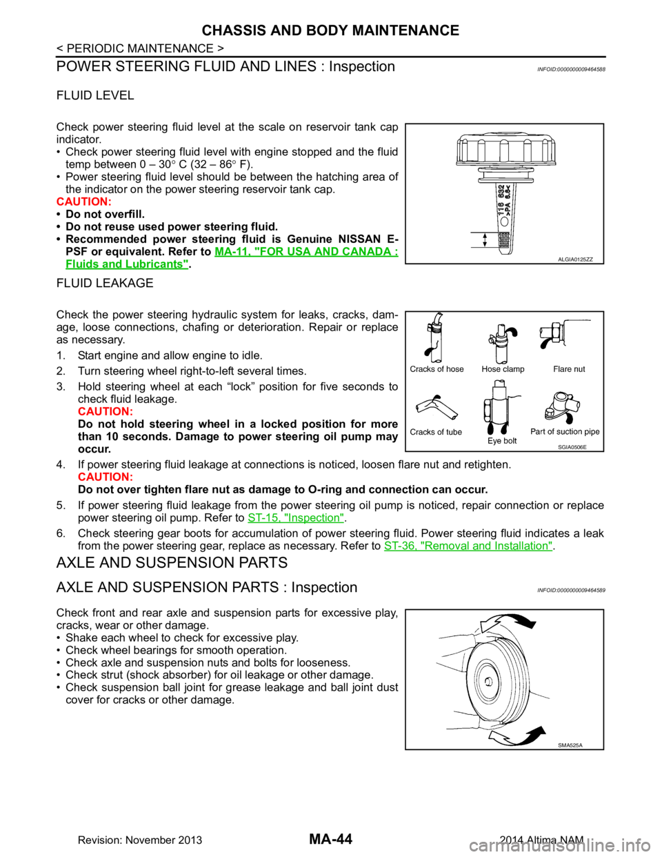
Check power steering fluid level at the scale on reservoir tank cap
indicator.
• Check power steering fluid level with engine stopped and the fluid temp between 0 – 30 ° C (32 – 86 ° F).
• Power steering fluid level should be between the hatching area of the indicator on the power steering reservoir tank cap.
CAUTION:
• Do not overfill.
• Do not reuse used power steering fluid.
• Recommended power steering fluid is Genuine NISSAN E-
PSF or equivalent. Refer to MA-11, "FOR USA AND CANADA :
Fluids and Lubricants".
FLUID LEAKAGE
Check the power steering hydraulic system for leaks, cracks, dam-
age, loose connections, chafing or det erioration. Repair or replace
as necessary.
1. Start engine and allow engine to idle.
2. Turn steering wheel right-to-left several times.
3. Hold steering wheel at each “lock” position for five seconds to check fluid leakage.
CAUTION:
Do not hold steering wheel in a locked position for more
than 10 seconds. Damage to power steering oil pump may
occur.
4. If power steering fluid leakage at connections is noticed, loosen flare nut and retighten.
CAUTION:
Do not over tighten flare nut as damage to O-ring and connection can occur.
5. If power steering fluid leakage from the power steer ing oil pump is noticed, repair connection or replace
power steering oil pump. Refer to ST-15, "Inspection"
.
6. Check steering gear boots for accumulation of power steering fluid. Power steering fluid indicates a leak from the power steering gear, replace as necessary. Refer to ST-36, "Removal and Installation"
.
AXLE AND SUSPENSION PARTS
AXLE AND SUSPENSION PARTS : InspectionINFOID:0000000009464589
Check front and rear axle and suspension parts for excessive play,
cracks, wear or other damage.
• Shake each wheel to check for excessive play.
• Check wheel bearings for smooth operation.
• Check axle and suspension nuts and bolts for looseness.
• Check strut (shock absorber) for oil leakage or other damage.
• Check suspension ball joint for grease leakage and ball joint dust cover for cracks or other damage.
ALGIA0125ZZ
SGIA0506E
SMA525A
Revision: November 20132014 Altima NAM
Page 3718 of 4801

RSU-1
SUSPENSION
C
D
F
G H
I
J
K L
M
SECTION RSU
A
B
RSU
N
O PCONTENTS
REAR SUSPENSION
PRECAUTION ................ ...............................2
PRECAUTIONS .............................................. .....2
Precaution for Supplemental Restraint System
(SRS) "AIR BAG" and "SEAT BELT PRE-TEN-
SIONER" ............................................................. ......
2
General Precautions .................................................2
PREPARATION ............................................3
PREPARATION .............................................. .....3
Commercial Service Tool .................................... ......3
SYMPTOM DIAGNOSIS ...............................4
NOISE, VIBRATION AND HARSHNESS
(NVH) TROUBLESHOOTING ........................ .....
4
NVH Troubleshooting Chart ................................ ......4
PERIODIC MAINTENANCE ..........................5
REAR SUSPENSION ASSEMBLY ................ .....5
On-vehicle Service .............................................. ......5
Inspection ..................................................................5
Inspection and Adjustment ........................................5
UNIT REMOVAL AND INSTALLATION .......8
REAR SUSPENSION ASSEMBLY ................ .....8
Exploded View .................................................... ......8
Removal and Installation ..................................... .....8
REMOVAL AND INSTALLATION ...............12
REAR LOWER LINK & COIL SPRING .............12
Removal and Installation ..................................... ....12
SHOCK ABSORBER ........................................13
Exploded View .........................................................13
Removal and Installation .........................................13
Disassembly and Assembly .....................................14
Disposal ...................................................................14
REAR STABILIZER ..........................................15
Exploded View .........................................................15
Removal and Installation .........................................15
SUSPENSION ARM ..........................................16
Exploded View .........................................................16
Removal and Installation .........................................16
SERVICE DATA AND SPECIFICATIONS
(SDS) ............... .............................................
17
SERVICE DATA AND SPECIFICATIONS
(SDS) .................................................................
17
General Specification (Rear) ............................... ....17
Wheel Alignment (Unladen*) ...................................17
Wheelarch Height (Unladen*1) ................................17
Revision: November 20132014 Altima NAM
Page 3719 of 4801
RSU-2
< PRECAUTION >
PRECAUTIONS
PRECAUTION
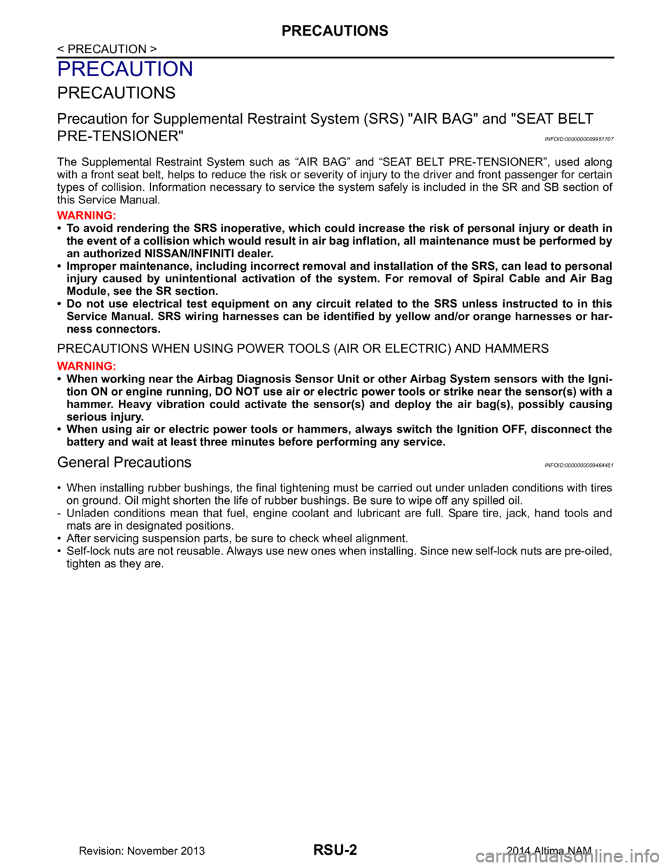
PRECAUTIONS
Precaution for Supplemental Restraint System (SRS) "AIR BAG" and "SEAT BELT
PRE-TENSIONER"
INFOID:0000000009951707
The Supplemental Restraint System such as “A IR BAG” and “SEAT BELT PRE-TENSIONER”, used along
with a front seat belt, helps to reduce the risk or severi ty of injury to the driver and front passenger for certain
types of collision. Information necessary to service the system safely is included in the SR and SB section of
this Service Manual.
WARNING:
• To avoid rendering the SRS inopera tive, which could increase the risk of personal injury or death in
the event of a collision which would result in air bag inflation, all maintenance must be performed by
an authorized NISS AN/INFINITI dealer.
• Improper maintenance, including in correct removal and installation of the SRS, can lead to personal
injury caused by unintent ional activation of the system. For re moval of Spiral Cable and Air Bag
Module, see the SR section.
• Do not use electrical test equipmen t on any circuit related to the SRS unless instructed to in this
Service Manual. SRS wiring harn esses can be identified by yellow and/or orange harnesses or har-
ness connectors.
PRECAUTIONS WHEN USING POWER TOOLS (AIR OR ELECTRIC) AND HAMMERS
WARNING:
• When working near the Airbag Diagnosis Sensor Unit or other Airbag System sensors with the Igni-
tion ON or engine running, DO NOT use air or electri c power tools or strike near the sensor(s) with a
hammer. Heavy vibration could activate the sensor( s) and deploy the air bag(s), possibly causing
serious injury.
• When using air or electric power tools or hammers , always switch the Ignition OFF, disconnect the
battery and wait at least three minutes before performing any service.
General PrecautionsINFOID:0000000009464451
• When installing rubber bushings, the final tightening mu st be carried out under unladen conditions with tires
on ground. Oil might shorten the life of rubber bushings. Be sure to wipe off any spilled oil.
- Unladen conditions mean that fuel, engine coolant and lubricant are full. Spare tire, jack, hand tools and mats are in designated positions.
• After servicing suspension parts, be sure to check wheel alignment.
• Self-lock nuts are not reusable. Always use new ones when installing. Since new self-lock nuts are pre-oiled,
tighten as they are.
Revision: November 20132014 Altima NAM
Page 3721 of 4801
RSU-4
< SYMPTOM DIAGNOSIS >
NOISE, VIBRATION AND HARSHNESS (NVH) TROUBLESHOOTING
SYMPTOM DIAGNOSIS
NOISE, VIBRATION AND HARSHNESS (NVH) TROUBLESHOOTING
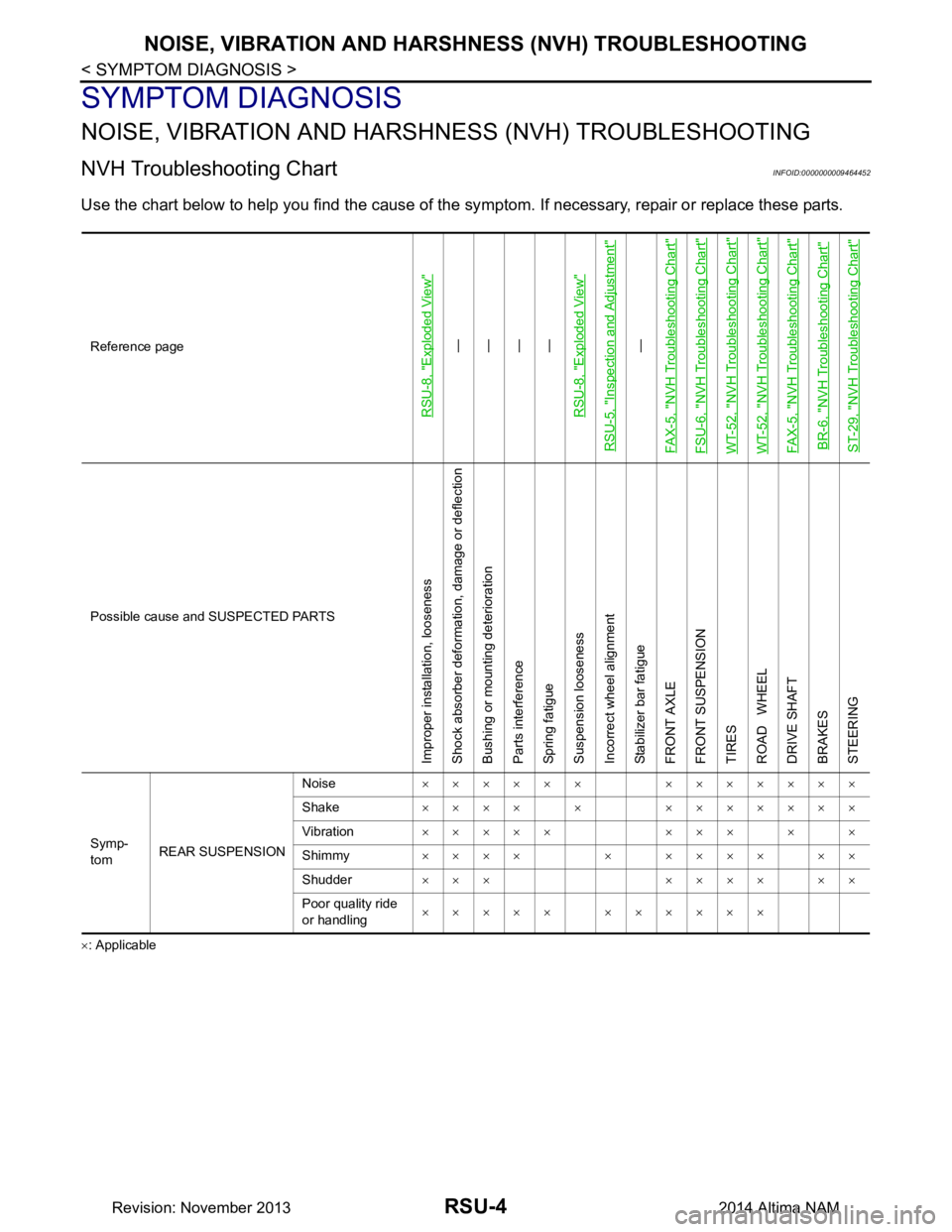
NVH Troubleshooting ChartINFOID:0000000009464452
Use the chart below to help you find the cause of the sy mptom. If necessary, repair or replace these parts.
×: ApplicableReference page
RSU-8, "Exploded View"
—
—
—
—
RSU-8, "Exploded View"
RSU-5, "Inspection and Adjustment"
—
FAX-5, "NVH Troubleshooting Chart"
FSU-6, "NVH Troubleshooting Chart"WT-52, "NVH Troubleshooting Chart"WT-52, "NVH Troubleshooting Chart"FAX-5, "NVH Troubleshooting Chart"BR-6, "NVH Troubleshooting Chart"ST-29, "NVH Troubleshooting Chart"
Possible cause and SUSPECTED PARTS
Improper installation, looseness
Shock absorber deformation, damage or deflection
Bushing or mounting deterioration
Parts interference
Spring fatigue
Suspension looseness
Incorrect wheel alignment
Stabilizer bar fatigue
FRONT AXLE
FRONT SUSPENSION
TIRES
ROAD WHEEL
DRIVE SHAFT
BRAKES
STEERING
Symp-
tom REAR SUSPENSION Noise
×××××× ×××××××
Shake ×××× × ×××××××
Vibration ××××× ××× × ×
Shimmy ×××× × ×××× ××
Shudder ××× ×××× ××
Poor quality ride
or handling ××××× ××××××
Revision: November 20132014 Altima NAM