2014 NISSAN TEANA DRIVER INFORMATION
[x] Cancel search: DRIVER INFORMATIONPage 3997 of 4801

SRC-4
< PRECAUTION >
PRECAUTIONS
PRECAUTION
PRECAUTIONS
Precaution for Supplemental Restraint System (SRS) "AIR BAG" and "SEAT BELT
PRE-TENSIONER"
INFOID:0000000009460702
The Supplemental Restraint System such as “A IR BAG” and “SEAT BELT PRE-TENSIONER”, used along
with a front seat belt, helps to reduce the risk or severi ty of injury to the driver and front passenger for certain
types of collision. Information necessary to service the system safely is included in the SR and SB section of
this Service Manual.
WARNING:
• To avoid rendering the SRS inopera tive, which could increase the risk of personal injury or death in
the event of a collision which would result in air bag inflation, all maintenance must be performed by
an authorized NISS AN/INFINITI dealer.
• Improper maintenance, including in correct removal and installation of the SRS, can lead to personal
injury caused by unintent ional activation of the system. For re moval of Spiral Cable and Air Bag
Module, see the SR section.
• Do not use electrical test equipmen t on any circuit related to the SRS unless instructed to in this
Service Manual. SRS wiring harn esses can be identified by yellow and/or orange harnesses or har-
ness connectors.
PRECAUTIONS WHEN USING POWER TOOLS (AIR OR ELECTRIC) AND HAMMERS
WARNING:
• When working near the Airbag Diagnosis Sensor Unit or other Airbag System sensors with the Igni-
tion ON or engine running, DO NOT use air or electri c power tools or strike near the sensor(s) with a
hammer. Heavy vibration could activate the sensor( s) and deploy the air bag(s), possibly causing
serious injury.
• When using air or electric power tools or hammers , always switch the Ignition OFF, disconnect the
battery and wait at least three minutes before performing any service.
Precaution for SRS "AIR BAG" and "S EAT BELT PRE-TENSIONER" Service
INFOID:0000000009460703
• Do not use electrical test equipment to check SRS ci rcuits unless instructed to in this Service Manual.
• Before servicing the SRS, turn ignition switch OFF, disconnect both battery cables and wait at least 3 min-
utes.
For approximately 3 minutes after the cables are removed, it is still possible for the air bag and seat belt pre-
tensioner to deploy. Therefore, do not work on any SR S connectors or wires until at least 3 minutes have
passed.
• The air bag diagnosis sensor unit must always be installed with the arrow mark “ ⇐” pointing toward the front
of the vehicle for proper operation. Also check air bag diagnosis sensor unit for cracks, deformities or rust
before installation and replace as required.
• The spiral cable must be aligned with the neutral position since its rotations are limited. Do not attempt to
turn steering wheel or column after removal of steering gear.
• Handle air bag module carefully. Always place driver and front passenger air bag modules with the pad side facing upward and seat mounted front side air bag m odule standing with the stud bolt side facing down.
• Conduct self-diagnosis to check entire SRS for proper function after replacing any components.
• After air bag inflates, the front instrument panel assembly should be replaced if damaged.
Revision: November 20132014 Altima NAMRevision: November 20132014 Altima NAM
Page 4008 of 4801
DIAGNOSIS SYSTEM (AIR BAG)SRC-15
< SYSTEM DESCRIPTION >
C
D E
F
G
I
J
K L
M A
B
SRC
N
O P
DIAGNOSIS SYSTEM (AIR BAG)
Diagnosis DescriptionINFOID:0000000009460723
CAUTION:
• Do not use electrical test equipment on any circui t related to the SRS unless instructed to do so in
this Service Manual. SRS wiring harnesses can be id entified by yellow and/or orange harness con-
nectors.
• Do not attempt to repair, splice or modify SRS wiring harnesses. If a harness is damaged, replace it
with a new one.
• Keep ground connections clean.
HOW TO PERFORM TROUBLE DIAGNOSES FOR QUICK AND ACCURATE REPAIR
1. Obtain information about the symptom.
- WHAT - vehicle model
- WHEN - date, frequencies
- WHERE - road conditions
- HOW - operating conditions, symptoms, passengers
2. Perform Preliminary Check.
-Battery
- Fuses
- Harness connections
DIAGNOSIS METHODS
SRS self-diagnosis results can be read by using the AIR BAG warning lamp or CONSULT.
The User Mode is for the customer (driver). This m ode warns the driver of a system malfunction through the
AIR BAG warning lamp.
The Diagnosis Mode is for the technician. This mode hel ps the technician locate the malfunctioning circuit or
part.
SRS Operation CheckINFOID:0000000009460724
USER MODE
1. Turn the ignition switch from OFF to ON and check that the air bag warning lamp flashes.
2. Compare the flashing pattern with the examples in the table.
User Mode Diagnosis Mode Display type
AIR BAG warning lamp X X ON/OFF CONSULT — X Monitoring
BF-1845D
Revision: November 20132014 Altima NAMRevision: November 20132014 Altima NAM
Page 4012 of 4801
DIAGNOSIS SENSOR UNITSRC-19
< ECU DIAGNOSIS INFORMATION >
C
D E
F
G
I
J
K L
M A
B
SRC
N
O P
ECU DIAGNOSIS INFORMATION
DIAGNOSIS SENSOR UNIT
DTC IndexINFOID:0000000009460731
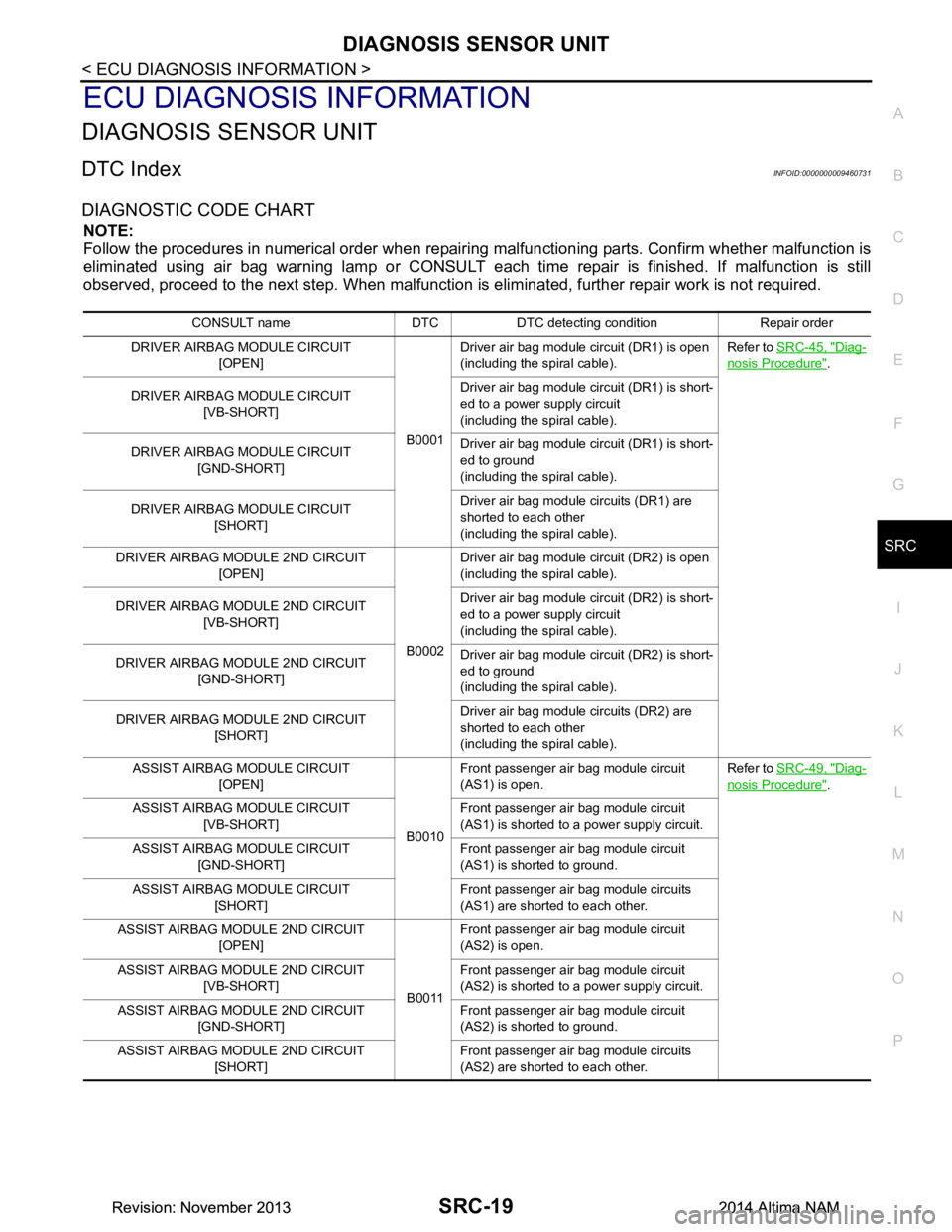
DIAGNOSTIC CODE CHART
NOTE:
Follow the procedures in numerical order when repairi ng malfunctioning parts. Confirm whether malfunction is
eliminated using air bag warning lamp or CONSULT each time repair is finished. If malfunction is still
observed, proceed to the next step. When malfunction is elim inated, further repair work is not required.
CONSULT name DTC DTC detecting condition Repair order
DRIVER AIRBAG MODULE CIRCUIT [OPEN]
B0001Driver air bag module circuit (DR1) is open
(including the spiral cable). Refer to
SRC-45, "Diag-
nosis Procedure".
DRIVER AIRBAG MODULE CIRCUIT [VB-SHORT] Driver air bag module circuit (DR1) is short-
ed to a power supply circuit
(including the spiral cable).
DRIVER AIRBAG MODULE CIRCUIT [GND-SHORT] Driver air bag module circuit (DR1) is short-
ed to ground
(including the spiral cable).
DRIVER AIRBAG MODULE CIRCUIT [SHORT] Driver air bag module circuits (DR1) are
shorted to each other
(including the spiral cable).
DRIVER AIRBAG MODULE 2ND CIRCUIT [OPEN]
B0002Driver air bag module circuit (DR2) is open
(including the spiral cable).
DRIVER AIRBAG MODULE 2ND CIRCUIT [VB-SHORT] Driver air bag module circuit (DR2) is short-
ed to a power supply circuit
(including the spiral cable).
DRIVER AIRBAG MODULE 2ND CIRCUIT [GND-SHORT] Driver air bag module circuit (DR2) is short-
ed to ground
(including the spiral cable).
DRIVER AIRBAG MODULE 2ND CIRCUIT [SHORT] Driver air bag module circuits (DR2) are
shorted to each other
(including the spiral cable).
ASSIST AIRBAG MODULE CIRCUIT [OPEN]
B0010Front passenger air bag module circuit
(AS1) is open. Refer to
SRC-49, "Diag-
nosis Procedure".
ASSIST AIRBAG MODULE CIRCUIT [VB-SHORT] Front passenger air bag module circuit
(AS1) is shorted to a power supply circuit.
ASSIST AIRBAG MODULE CIRCUIT [GND-SHORT] Front passenger air bag module circuit
(AS1) is shorted to ground.
ASSIST AIRBAG MODULE CIRCUIT [SHORT] Front passenger air bag module circuits
(AS1) are shorted to each other.
ASSIST AIRBAG MODULE 2ND CIRCUIT [OPEN]
B0011Front passenger air bag module circuit
(AS2) is open.
ASSIST AIRBAG MODULE 2ND CIRCUIT [VB-SHORT] Front passenger air bag module circuit
(AS2) is shorted to a power supply circuit.
ASSIST AIRBAG MODULE 2ND CIRCUIT [GND-SHORT] Front passenger air bag module circuit
(AS2) is shorted to ground.
ASSIST AIRBAG MODULE 2ND CIRCUIT [SHORT] Front passenger air bag module circuits
(AS2) are shorted to each other.
Revision: November 20132014 Altima NAMRevision: November 20132014 Altima NAM
Page 4016 of 4801
DIAGNOSIS SENSOR UNITSRC-23
< ECU DIAGNOSIS INFORMATION >
C
D E
F
G
I
J
K L
M A
B
SRC
N
O P
Flash Code IndexINFOID:0000000009460732
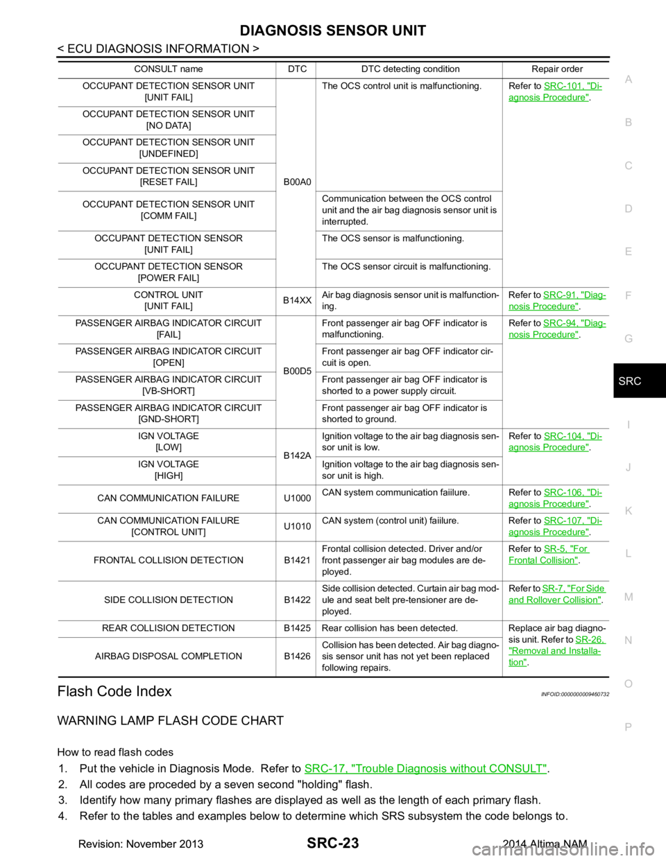
WARNING LAMP FLASH CODE CHART
How to read flash codes
1. Put the vehicle in Diagnosis Mode. Refer to SRC-17, "Trouble Diagnosis without CONSULT".
2. All codes are proceded by a seven second "holding" flash.
3. Identify how many primary flashes are display ed as well as the length of each primary flash.
4. Refer to the tables and examples below to determine which SRS subsystem the code belongs to.
OCCUPANT DETECTION SENSOR UNIT [UNIT FAIL]
B00A0The OCS control unit is malfunctioning. Refer to
SRC-101, "Di-
agnosis Procedure".
OCCUPANT DETECTION SENSOR UNIT [NO DATA]
OCCUPANT DETECTION SENSOR UNIT [UNDEFINED]
OCCUPANT DETECTION SENSOR UNIT [RESET FAIL]
OCCUPANT DETECTION SENSOR UNIT [COMM FAIL] Communication between the OCS control
unit and the air bag diagnosis sensor unit is
interrupted.
OCCUPANT DETECTION SENSOR [UNIT FAIL] The OCS sensor is malfunctioning.
OCCUPANT DETECTION SENSOR [POWER FAIL] The OCS sensor circuit is malfunctioning.
CONTROL UNIT [UNIT FAIL] B14XX
Air bag diagnosis sensor unit is malfunction-
ing. Refer to
SRC-91, "Diag-
nosis Procedure".
PASSENGER AIRBAG INDICATOR CIRCUIT [FAIL]
B00D5Front passenger air bag OFF indicator is
malfunctioning. Refer to
SRC-94, "Diag-
nosis Procedure".
PASSENGER AIRBAG INDICATOR CIRCUIT [OPEN] Front passenger air bag OFF indicator cir-
cuit is open.
PASSENGER AIRBAG INDICATOR CIRCUIT [VB-SHORT] Front passenger air bag OFF indicator is
shorted to a power supply circuit.
PASSENGER AIRBAG INDICATOR CIRCUIT [GND-SHORT] Front passenger air bag OFF indicator is
shorted to ground.
IGN VOLTAGE [LOW] B142AIgnition voltage to the air bag diagnosis sen-
sor unit is low. Refer to
SRC-104, "Di-
agnosis Procedure".
IGN VOLTAGE [HIGH] Ignition voltage to the air bag diagnosis sen-
sor unit is high.
CAN COMMUNICATION FAILURE U1000 CAN system communication faiilure. Refer to
SRC-106, "Di-
agnosis Procedure".
CAN COMMUNICATION FAILURE [CONTROL UNIT] U1010CAN system (control unit) faiilure. Refer to
SRC-107, "Di-
agnosis Procedure".
FRONTAL COLLISION DETECTION B1421 Frontal collision detected. Driver and/or
front passenger air bag modules are de-
ployed. Refer to
SR-5, "For
Frontal Collision".
SIDE COLLISION DETECTION B1422 Side collision detected. Curtain air bag mod-
ule and seat belt pre-tensioner are de-
ployed. Refer to
SR-7, "For Side
and Rollover Collision".
REAR COLLISION DETECTION B1425 Rear collision has been detected. Replace air bag diagno- sis unit. Refer to SR-26,
"Removal and Installa-
tion".
AIRBAG DISPOSAL COMPLETION B1426 Collision has been detected. Air bag diagno-
sis sensor unit has not yet been replaced
following repairs.
CONSULT name DTC DTC detecting condition Repair order
Revision: November 20132014 Altima NAMRevision: November 20132014 Altima NAM
Page 4017 of 4801
SRC-24
< ECU DIAGNOSIS INFORMATION >
DIAGNOSIS SENSOR UNIT
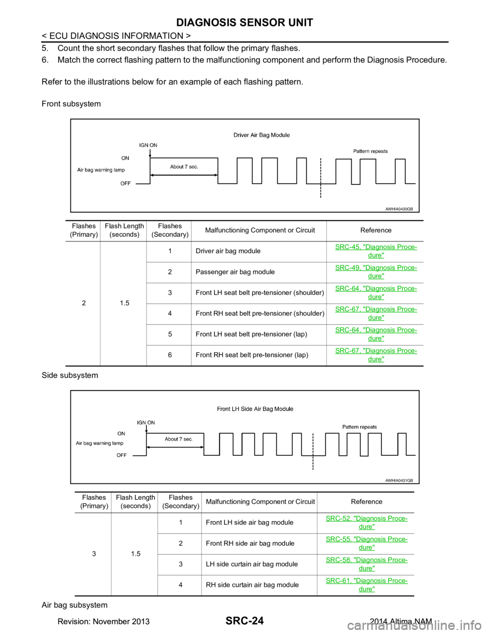
5. Count the short secondary flashes that follow the primary flashes.
6. Match the correct flashing pattern to the ma lfunctioning component and perform the Diagnosis Procedure.
Refer to the illustrations below fo r an example of each flashing pattern.
Front subsystem
Side subsystem
Air bag subsystem
AWHIA0430GB
Flashes
(Primary) Flash Length
(seconds) Flashes
(Secondary) Malfunctioning Component or Circuit Reference
21.5 1 Driver air bag module
SRC-45, "Diagnosis Proce-
dure"
2 Passenger air bag moduleSRC-49, "Diagnosis Proce-dure"
3 Front LH seat belt pre-tensioner (shoulder)SRC-64, "Diagnosis Proce-dure"
4 Front RH seat belt pre-tensioner (shoulder)
SRC-67, "Diagnosis Proce-dure"
5 Front LH seat belt pre-tensioner (lap)SRC-64, "Diagnosis Proce-dure"
6 Front RH seat belt pre-tensioner (lap)SRC-67, "Diagnosis Proce-dure"
AWHIA0431GB
Flashes
(Primary) Flash Length
(seconds) Flashes
(Secondary) Malfunctioning Component or Circuit Reference
31.5 1 Front LH side air bag module
SRC-52, "Diagnosis Proce-
dure"
2 Front RH side air bag moduleSRC-55, "Diagnosis Proce-dure"
3 LH side curtain air bag module
SRC-58, "Diagnosis Proce-dure"
4 RH side curtain air bag moduleSRC-61, "Diagnosis Proce-dure"
Revision: November 20132014 Altima NAMRevision: November 20132014 Altima NAM
Page 4106 of 4801
PRECAUTIONSST-3
< PRECAUTION >
C
D E
F
H I
J
K L
M A
B
ST
N
O P
PRECAUTION
PRECAUTIONS
Precaution for Supplemental Restraint System (SRS) "AIR BAG" and "SEAT BELT
PRE-TENSIONER"
INFOID:0000000009951723
The Supplemental Restraint System such as “A IR BAG” and “SEAT BELT PRE-TENSIONER”, used along
with a front seat belt, helps to reduce the risk or severi ty of injury to the driver and front passenger for certain
types of collision. Information necessary to service t he system safely is included in the SR and SB section of
this Service Manual.
WARNING:
• To avoid rendering the SRS inoper ative, which could increase the risk of personal injury or death in
the event of a collision which would result in air bag inflation, all maintenance must be performed by
an authorized NISSAN/INFINITI dealer.
• Improper maintenance, including in correct removal and installation of the SRS, can lead to personal
injury caused by unintentional act ivation of the system. For removal of Spiral Cable and Air Bag
Module, see the SR section.
• Do not use electrical test equipm ent on any circuit related to the SRS unless instructed to in this
Service Manual. SRS wiring harnesses can be identi fied by yellow and/or orange harnesses or har-
ness connectors.
PRECAUTIONS WHEN USING POWER TOOLS (AIR OR ELECTRIC) AND HAMMERS
WARNING:
• When working near the Airbag Diagnosis Sensor Un it or other Airbag System sensors with the Igni-
tion ON or engine running, DO NOT use air or el ectric power tools or strike near the sensor(s) with a
hammer. Heavy vibration could activate the sensor( s) and deploy the air bag(s), possibly causing
serious injury.
• When using air or electric power tools or hammers , always switch the Ignition OFF, disconnect the
battery and wait at least three mi nutes before performing any service.
Precaution for Steering SystemINFOID:0000000009461240
• Before disassembly, thoroughly clean the outside of the unit.
• Disassembly should be done in a clean work area. It is im portant to prevent the internal parts from becoming
contaminated by dirt or other foreign matter.
• For easier and proper assembly, place disassembled parts in order on a parts rack.
• Use nylon cloth or paper towels to clean the parts; common shop rags can leave lint that might interfere with
their operation.
• Before inspection or reassembly, carefully clean al l parts with a general purpose, non-flammable solvent.
• Before assembly, apply a coat of recommended Genuine NISSAN PSF or equivalent to hydraulic parts.
Petroleum jelly may be applied to O-rings and seals. Do not use any grease.
• Replace all gaskets, seals and O-rings. Avoid damaging O-rings, seals and gaskets during installation. Per- form functional tests whenever designated.
Precaution for WorkINFOID:0000000009461241
• When removing or disassembling each component, be ca reful not to damage or deform it. If a component
may be subject to interference, be sure to protect it with a shop cloth.
• When removing (disengaging) components with a screwdriver or similar tool, be sure to wrap the component
with a shop cloth or vinyl tape to protect it.
• Protect the removed parts with a shop cloth and prevent them from being dropped.
• Replace a deformed or damaged clip.
• If a part is specified as a non-reusabl e part, always replace it with a new one.
• Be sure to tighten bolts and nuts securely to the specified torque.
• After installation is complete, be sure to check that each part works properly.
• Follow the steps below to clean components:
- Water soluble dirt:
• Dip a soft cloth into lukewarm water, wring the water out of the cloth and wipe the dirty area.
• Then rub with a soft, dry cloth.
-Oily dirt:
Revision: November 20132014 Altima NAMRevision: November 20132014 Altima NAM
Page 4154 of 4801
PRECAUTIONSSTC-3
< PRECAUTION >
C
D E
F
H I
J
K L
M A
B
STC
N
O P
PRECAUTION
PRECAUTIONS
Precaution for Supplemental Restraint System (SRS) "AIR BAG" and "SEAT BELT
PRE-TENSIONER"
INFOID:0000000009951730
The Supplemental Restraint System such as “A IR BAG” and “SEAT BELT PRE-TENSIONER”, used along
with a front seat belt, helps to reduce the risk or severi ty of injury to the driver and front passenger for certain
types of collision. Information necessary to service t he system safely is included in the SR and SB section of
this Service Manual.
WARNING:
• To avoid rendering the SRS inoper ative, which could increase the risk of personal injury or death in
the event of a collision which would result in air bag inflation, all maintenance must be performed by
an authorized NISSAN/INFINITI dealer.
• Improper maintenance, including in correct removal and installation of the SRS, can lead to personal
injury caused by unintentional act ivation of the system. For removal of Spiral Cable and Air Bag
Module, see the SR section.
• Do not use electrical test equipm ent on any circuit related to the SRS unless instructed to in this
Service Manual. SRS wiring harnesses can be identi fied by yellow and/or orange harnesses or har-
ness connectors.
PRECAUTIONS WHEN USING POWER TOOLS (AIR OR ELECTRIC) AND HAMMERS
WARNING:
• When working near the Airbag Diagnosis Sensor Un it or other Airbag System sensors with the Igni-
tion ON or engine running, DO NOT use air or el ectric power tools or strike near the sensor(s) with a
hammer. Heavy vibration could activate the sensor( s) and deploy the air bag(s), possibly causing
serious injury.
• When using air or electric power tools or hammers , always switch the Ignition OFF, disconnect the
battery and wait at least three mi nutes before performing any service.
Service Notice and Precautions for Hydrau lic Pump Electric Power Steering System
INFOID:0000000009460340
• Check each tire for proper air pressure and size. Refer to WT-60, "Tire".
• Verify that the steering system components are G enuine NISSAN parts and have been installed properly.
• Check the steering column for loose mounting bolts.
• Check the steering gear assembly for loose mounting bolts. Check the inner sockets and outer sockets for
damage or wear. Inspect the boots and seals for leakage of power steering fluid.
• Verify proper wheel alignment. Refer to FSU-7, "Inspection and Adjustment"
.
• Check for any damage, wear, or modification to the suspension and body that would result in increased
weight or an improper wheelarch height. Refer to FSU-26, "Wheelarch Height (Unladen*
1)".
• Check for proper battery voltage.
• Verify that all power steering pump assembly connections are clean and fully seated.
• Verify that only Genuine NISSAN E-PSF is used. Use of any power steering fluid other than Genuine NIS-
SAN E-PSF will prevent the power st eering system from proper operation.
• An audible high pitch noise may be heard from the engine compartment when the steering wheel is oper-
ated, particularly at low speeds such as a parking lot maneuver. This condition is not a malfunction, rather
normal system operation. Steering at low speeds or parking lot maneuvers demands higher hydraulic assis-
tance, resulting in larger power st eering pump load and increased system noise.
• The power steering pump is electrically controlled by the power steering control module.
• Before connecting or disconnecting the power steeri ng control module harness connectors, turn ignition
switch “OFF” and disconnect battery ground cable. Batter y voltage is applied to power steering control mod-
ule even if ignition switch is turned “OFF”.
Revision: November 20132014 Altima NAMRevision: November 20132014 Altima NAM
Page 4163 of 4801
STC-12
< ECU DIAGNOSIS INFORMATION >
POWER STEERING CONTROL MODULE
*4: This may not agree with the speedometer indication immediately after the ignition switch is turned ON. This
is not a malfunction.
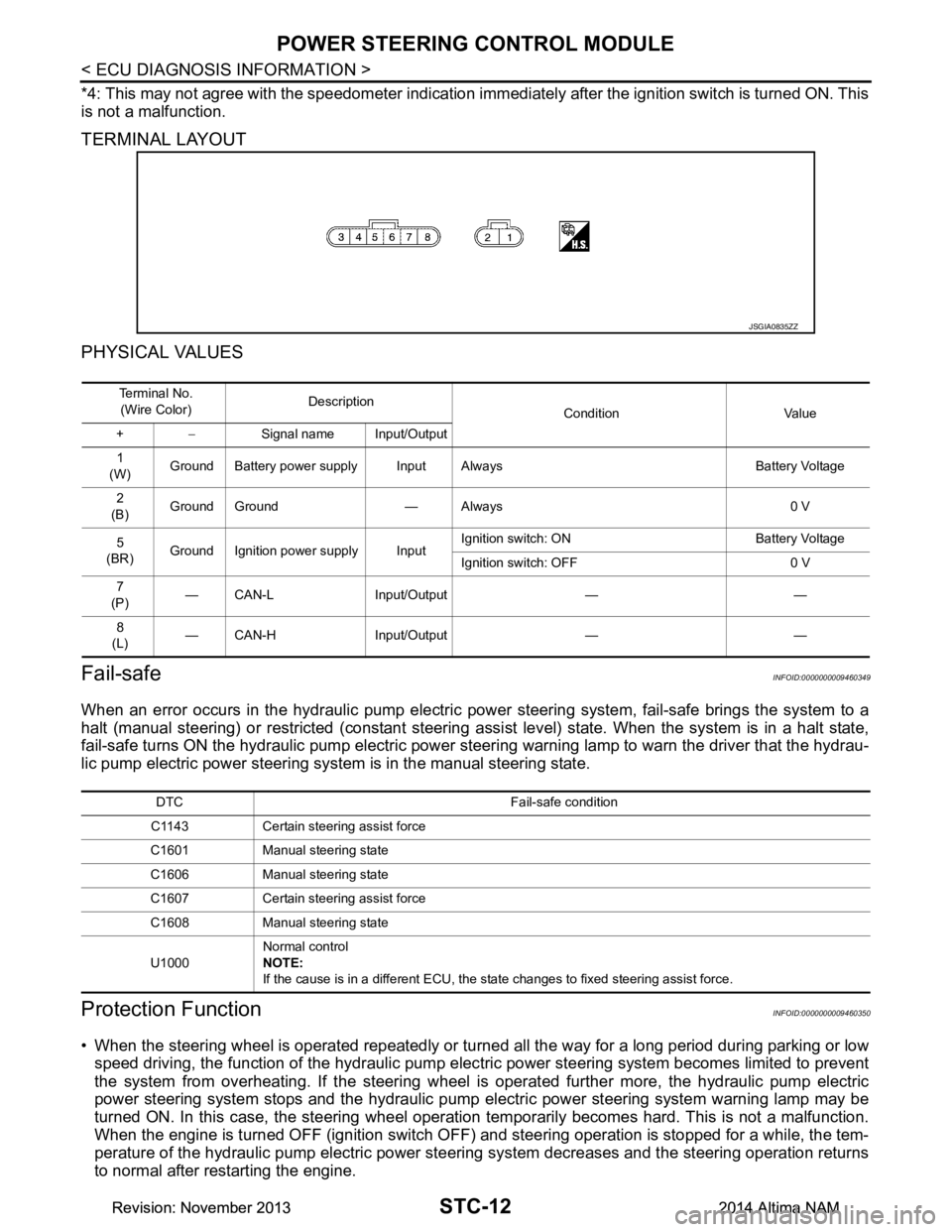
TERMINAL LAYOUT
PHYSICAL VALUES
Fail-safeINFOID:0000000009460349
When an error occurs in the hydraulic pump electric pow er steering system, fail-safe brings the system to a
halt (manual steering) or restricted (constant steering assi st level) state. When the system is in a halt state,
fail-safe turns ON the hydraulic pump electric power steer ing warning lamp to warn the driver that the hydrau-
lic pump electric power steering system is in the manual steering state.
Protection FunctionINFOID:0000000009460350
• When the steering wheel is operated repeatedly or turned all the way for a long period during parking or low
speed driving, the function of the hydraulic pump elec tric power steering system becomes limited to prevent
the system from overheating. If the steering wheel is operated further more, the hydraulic pump electric
power steering system stops and the hydraulic pump el ectric power steering system warning lamp may be
turned ON. In this case, the steering wheel operation temporarily becomes hard. This is not a malfunction.
When the engine is turned OFF (ignition switch OFF) and steering operation is stopped for a while, the tem-
perature of the hydraulic pump electric power steeri ng system decreases and the steering operation returns
to normal after restarting the engine.
JSGIA0835ZZ
Te r m i n a l N o .
(Wire Color) Description
Condition Value
+ − Signal name Input/Output
1
(W) Ground Battery power supply Input Always Battery Voltage
2
(B) Ground Ground — Always 0 V
5
(BR) Ground Ignition power supply Input Ignition switch: ON Battery Voltage
Ignition switch: OFF 0 V
7
(P) — CAN-L Input/Output — —
8
(L) — CAN-H Input/Output — —
DTC Fail-safe condition
C1143 Certain steering assist force
C1601 Manual steering state
C1606 Manual steering state
C1607 Certain steering assist force
C1608 Manual steering state
U1000 Normal control
NOTE:
If the cause is in a different ECU, the state changes to fixed steering assist force.
Revision: November 20132014 Altima NAMRevision: November 20132014 Altima NAM