2014 NISSAN TEANA air condition
[x] Cancel search: air conditionPage 4586 of 4801
![NISSAN TEANA 2014 Service Manual
SHIFT LOCK SYSTEMTM-371
< DTC/CIRCUIT DIAGNOSIS > [CVT: RE0F10E]
C
EF
G H
I
J
K L
M A
B
TM
N
O P
NO >> Repair or replace damaged parts.
9.CHECK GROUND CIRCUIT (CVT SHIFT SELECTOR)
Check continuity b NISSAN TEANA 2014 Service Manual
SHIFT LOCK SYSTEMTM-371
< DTC/CIRCUIT DIAGNOSIS > [CVT: RE0F10E]
C
EF
G H
I
J
K L
M A
B
TM
N
O P
NO >> Repair or replace damaged parts.
9.CHECK GROUND CIRCUIT (CVT SHIFT SELECTOR)
Check continuity b](/manual-img/5/57390/w960_57390-4585.png)
SHIFT LOCK SYSTEMTM-371
< DTC/CIRCUIT DIAGNOSIS > [CVT: RE0F10E]
C
EF
G H
I
J
K L
M A
B
TM
N
O P
NO >> Repair or replace damaged parts.
9.CHECK GROUND CIRCUIT (CVT SHIFT SELECTOR)
Check continuity between CVT shift selector connector M23 terminal 4 and ground.
Is the inspection result normal?
YES >> Replace CVT shift selector. Refer to TM-378, "Removal and Installation".
NO >> Repair or replace damaged parts.
Component Inspection (Shift Lock Solenoid)INFOID:0000000009464327
1.CHECK SHIFT LOCK SOLENOID
Apply voltage to terminals of shift lock solenoid and park position switch (shift selector) connector and check
that shift lock solenoid is activated.
CAUTION:
• Connect the fuse between the termi nals when applying the voltage.
• Never cause shorting between terminals.
Is the inspection result normal?
YES >> Inspection End.
NO >> Replace CVT shift selector. Refer to TM-378, "Removal and Installation"
.
Component Inspection (Park Position Switch)INFOID:0000000009464328
1.CHECK PARK POSITION SWITCH (SHIFT SELECTOR)
Apply voltage to terminals of shift lock solenoid and park position switch (shift selector) connector and check
that shift lock solenoid is activated.
CAUTION:
• Connect the fuse between the termi nals when applying the voltage.
• Never cause shorting between terminals.
Is the inspection result normal?
YES >> Inspection End.
NO >> Replace CVT shift selector. Refer to TM-378, "Removal and Installation"
.
CVT shift selector
GroundContinuity
Connector Terminal
M23 4 Yes
+ (fuse) - Condition Status
Shift lock solenoid
Te r m i n a l
34 Apply 12 V between termi-
nals 3 and 4 with the park
position switch (shift selec-
tor) in the "P" (park) posi-
tion. Shift lock solenoid operates
+ (fuse) -
Condition Status
Shift lock solenoid
Te r m i n a l
34 Apply 12 V between termi-
nals 3 and 4 with the park
position switch (shift selec-
tor) in the "P" (park) posi-
tion. Shift lock solenoid operates
Revision: November 20132014 Altima NAMRevision: November 20132014 Altima NAM
Page 4629 of 4801

VTL-1
VENTILATION, HEATER & AIR CONDITIONER
C
D E
F
G H
J
K L
M
SECTION VTL
A
B
VTL
N
O P
CONTENTS
VENTILATION SYSTEM
PRECAUTION ................ ...............................2
PRECAUTIONS .............................................. .....2
Precaution for Supplemental Restraint System
(SRS) "AIR BAG" and "SEAT BELT PRE-TEN-
SIONER" ............................................................. ......
2
Precaution for Work ..................................................2
PREPARATION ............................................3
PREPARATION .............................................. .....3
Special Service Tool ........................................... ......3
Commercial Service Tool ..........................................3
PERIODIC MAINTENANCE ..........................4
IN-CABIN MICROFILTER .............................. .....4
Removal and Installation ...........................................4
SYSTEM DESCRIPTION . .............................5
IN-CABIN MICROFILTER .............................. .....5
Description .......................................................... ......5
REMOVAL AND INSTALLATION ................6
DUCTS AND GRILLES .................................. .....6
Exploded View .................................................... ......6
DEFROSTER NOZZLE .......................................... ......7
DEFROSTER NOZZLE : Removal and Installation
......
7
CENTER VENTILATOR DUCT .............................. ......7
CENTER VENTILATOR DUCT : Removal and In-
stallation .............................................................. ......
7
SIDE DEFROSTER DUCT ..................................... ......7
SIDE DEFROSTER DUCT : Removal and Instal-
lation .................................................................... ......
7
FRONT FLOOR DUCT .......................................... ......8
FRONT FLOOR DUCT : Removal and Installation
- Front Floor Duct ................................................ .....
8
FRONT FLOOR DUCT : Removal and Installation
- Front Floor Connecting Duct ............................. .....
8
FRONT FLOOR DUCT : Removal and Installation
- Front Floor Duct Nozzle .................................... .....
8
ADAPTOR DUCT ................................................... .....8
ADAPTOR DUCT : Removal and Installation -
Adaptor Duct ........................................................ .....
8
ADAPTOR DUCT : Removal and Installation -
Adaptor Extension Duct ....................................... .....
9
REAR CENTER VENTILATOR DUCT ................... .....9
REAR CENTER VENTILATOR DUCT : Removal
and Installation .................................................... .....
9
Exploded View .........................................................10
CENTER VENTILATOR GRILLE ........................... ....10
CENTER VENTILATOR GRILLE : Removal and
Installation ........................................................... ....
11
SIDE VENTILATOR GRILLE ................................. ....11
SIDE VENTILATOR GRILLE : Removal and In-
stallation .............................................................. ....
11
SIDE DEFROSTER GRILLE .................................. ....11
SIDE DEFROSTER GRILLE : Removal and In-
stallation .............................................................. ....
11
REAR CENTER VENTILATOR GRILLE ............... ....12
REAR CENTER VENTILATOR GRILLE : Remov-
al and Installation ................................................. ....
12
BLOWER UNIT .................................................13
BLOWER UNIT ...................................................... ....13
BLOWER UNIT : Exploded View .............................13
BLOWER UNIT : Removal and Installation .............13
BLOWER MOTOR ................................................. ....13
BLOWER MOTOR : Removal and Installation ........13
Revision: November 20132014 Altima NAM
Page 4653 of 4801
![NISSAN TEANA 2014 Service Manual
WCS
DIAGNOSIS SYSTEM (METER)WCS-11
< SYSTEM DESCRIPTION >
C
D E
F
G H
I
J
K L
M B
A
O P
FUEL W/L
[On/Off] Displays [ON/OFF] condition of low-fuel warning message.
WASHER W/L
[On/Off] Displays [ON/ NISSAN TEANA 2014 Service Manual
WCS
DIAGNOSIS SYSTEM (METER)WCS-11
< SYSTEM DESCRIPTION >
C
D E
F
G H
I
J
K L
M B
A
O P
FUEL W/L
[On/Off] Displays [ON/OFF] condition of low-fuel warning message.
WASHER W/L
[On/Off] Displays [ON/](/manual-img/5/57390/w960_57390-4652.png)
WCS
DIAGNOSIS SYSTEM (METER)WCS-11
< SYSTEM DESCRIPTION >
C
D E
F
G H
I
J
K L
M B
A
O P
FUEL W/L
[On/Off] Displays [ON/OFF] condition of low-fuel warning message.
WASHER W/L
[On/Off] Displays [ON/OFF] condition of low washer fluid warning message.
AIR PRES W/L
[ON/OFF] Displays [ON/OFF] condition of tire pressure warning lamp.
KEY G/Y W/L
[On/Off] Displays [ON/OFF] condition of key green warning lamp.
EPS W/L
[On/Off] Displays [ON/OFF] condition of EPS warning indicator.
LCD Displays the value of Intelligent Key system message indication.
ACC SET SPEED
[Off, km/h or mph] Displays OFF or SET vehicle speed status in the information display.
ACC UNIT
[On/Off] Displays [ON/OFF] condition of display unit in the information display.
SHIFT IND
[P, R, N, D, DS] Displays [P, R, N, D, DS] shift selector position.
FUEL CAP W/L
[On/Off] Displays [ON/OFF] condition of loose fuel cap warning message.
O/D OFF SW
[ON/OFF] Displays [ON/OFF] condition of O/D OFF switch.
M RANGE SW
[On/Off] Displays [ON/OFF] condition of manual mode switch.
NM RANGE SW
[On/Off] Displays [ON/OFF] condition of non-manual mode switch.
AT SFT UP SW
[On/Off] Displays [ON/OFF] condition of manual mode shift up switch.
AT SFT DWN SW
[On/Off] Displays [ON/OFF] condition of manual mode shift down switch.
ST SFT UP SW
[On/Off] Displays [ON/OFF] condition of paddle shift up switch.
ST SFT DWN SW
[On/Off] Displays [ON/OFF] condition of paddle shift down switch.
PKB SW
[On/Off] Displays [ON/OFF] condition of parking brake switch.
BUCKLE SW
[ON/OFF] Status of seat belt buckle switch (LH).
BRAKE OIL SW
[On/Off] Displays [ON/OFF] condition of brake fluid level switch.
PASS BUCKLE SW
[ON/OFF] Status of passenger seat belt buckle switch (RH).
DISTANCE
[Mi] or [km] Displays distance to empty.
OUTSIDE TEMP
[ ° F or °C] Displaysthe ambient air temperature which is input from the ambient sensor.
FUEL LOW SIG
[On/Off] Displays [ON/OFF] condition of low-fuel warning signal.
BUZZER
[On/Off] XBuzzer status (in the combination meter) is detected from the buzzer output signal
received from each unit via CAN communication and the warning output condition
of the combination meter.
BSW IND
[ON/OFF] Displays [ON/OFF] condition of BSW warning indicator message in the informa-
tion display.
Display item [Unit]
MAIN
SIGNALS Description
Revision: November 20132014 Altima NAMRevision: November 20132014 Altima NAM
Page 4655 of 4801

WCS
DIAGNOSIS SYSTEM (BCM)WCS-13
< SYSTEM DESCRIPTION >
C
D E
F
G H
I
J
K L
M B
A
O P
DIAGNOSIS SYSTEM (BCM)
COMMON ITEM
COMMON ITEM : CONSULT Function (BCM - COMMON ITEM)INFOID:0000000009941192
CAUTION:
After disconnecting the CONSULT vehicle interface (VI) from the data link connector, the ignition must
be cycled OFF → ON (for at least 5 seconds) → OFF. If this step is not performed, the BCM may not go
to ”sleep mode”, potentiall y causing a discharged battery and a no-start condition.
APPLICATION ITEM
CONSULT performs the following functions via CAN communication with BCM.
SYSTEM APPLICATION
BCM can perform the following functions.
Direct Diagnostic Mode Description
Ecu Identification The BCM part number is displayed.
Self Diagnostic Result The BCM self diagnostic results are displayed.
Data Monitor The BCM input/output data is displayed in real time.
Active Test The BCM activates outputs to test components.
Work support The settings for BCM functions can be changed.
Configuration • The vehicle specification can be read and saved.
• The vehicle specification can be written when replacing BCM.
CAN Diag Support Mntr The result of transmit/receive diagnosis of CAN communication is displayed.
System Sub System Direct Diagnostic Mode
Ecu Identification
Self Diagnostic Result
Data Monitor
Active Test
Work support
Configuration
CAN Diag Su pport Mntr
Door lock DOOR LOCK ××××
Rear window defogger REAR DEFOGGER ×××
Warning chime BUZZER ××
Interior room lamp timer INT LAMP ×××
Remote keyless entry system MULTI REMOTE ENT ×××
Exterior lamp HEADLAMP ×××
Wiper and washer WIPER ×××
Turn signal and hazard warning lamps FLASHER ××
Air conditioner AIR CONDITIONER ×
Intelligent Key system INTELLIGENT KEY ××××
Combination switch COMB SW ×
BCM BCM × × ×××
Immobilizer IMMU ×××
Interior room lamp battery saver BATTERY SAVER ××
Trunk open TRUNK ×
Vehicle security system THEFT ALM ×××
Revision: November 20132014 Altima NAMRevision: November 20132014 Altima NAM
Page 4656 of 4801

WCS-14
< SYSTEM DESCRIPTION >
DIAGNOSIS SYSTEM (BCM)
BUZZER
BUZZER : CONSULT Function (BCM - BUZZER)INFOID:0000000009941193
CAUTION:
After disconnecting the CONSULT vehicle interface (VI) from the data link connector, the ignition must
be cycled OFF → ON (for at least 5 seconds) → OFF. If this step is not performed, the BCM may not go
to ”sleep mode”, potentially causing a di scharged battery and a no-start condition.
DATA MONITOR
ACTIVE TEST
RAP system RETAINED PWR ×
Signal buffer system SIGNAL BUFFER ×
TPMS AIR PRESSURE MONITOR ××××
System Sub System
Direct Diagnostic Mode
Ecu Identification
Self Diagnostic Result
Data Monitor
Active Test
Work support
Configuration
CAN Diag Support Mntr
Monitor Item [Unit] Description
PUSH -SW [On/Off] Indicates condition of push-button ignition switch.
UNLK SEN -DR [On/Off] Indicates condition of door unlock sensor.
VEH SPEED 1 [km/h] Indicates vehicle speed signal received from ABS on CAN communication line.
TAIL LAMP SW [On/Off] Indicates condition of combination switch.
FR FOG SW [On/Off] Indicates condition of front fog lamp switch.
DOOR SW-DR [On/Off] Indicates condition of front door switch LH.
CDL LOCK SW [On/Off] Indicates condition of lock signal from door lock and unlock switch.
Test Item Description
SEAT BELT WARN TEST This test is able to check seat belt warning chime operation [On/Off].
LIGHT WARN ALM This test is able to check light warning chime operation [On/Off].
REVERSE WARNING This test is able to check reverse warning chime operation [On/Off].
ID REGIST WARNING This test is able to check TPMS transmitter ID regist warning chime operation [On/Off].
Revision: November 20132014 Altima NAMRevision: November 20132014 Altima NAM
Page 4665 of 4801

WCS
DIAGNOSIS AND REPAIR WORKFLOWWCS-23
< BASIC INSPECTION >
C
D E
F
G H
I
J
K L
M B
A
O P
BASIC INSPECTION
DIAGNOSIS AND REPAIR WORKFLOW
Work FlowINFOID:0000000009462893
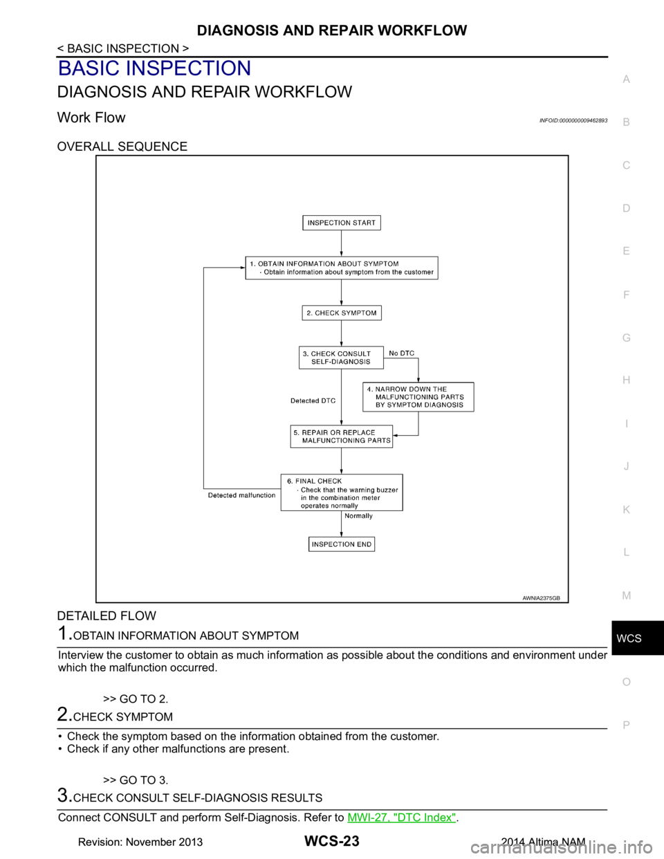
OVERALL SEQUENCE
DETAILED FLOW
1.OBTAIN INFORMATION ABOUT SYMPTOM
Interview the customer to obtain as much informa tion as possible about the conditions and environment under
which the malfunction occurred.
>> GO TO 2.
2.CHECK SYMPTOM
• Check the symptom based on the information obtained from the customer.
• Check if any other malfunctions are present.
>> GO TO 3.
3.CHECK CONSULT SELF-DIAGNOSIS RESULTS
Connect CONSULT and perform Self-Diagnosis. Refer to MWI-27, "DTC Index"
.
AWNIA2375GB
Revision: November 20132014 Altima NAMRevision: November 20132014 Altima NAM
Page 4671 of 4801

WCS
SEAT BELT BUCKLE SWITCH SIGNAL CIRCUIT
WCS-29
< DTC/CIRCUIT DIAGNOSIS >
C
D E
F
G H
I
J
K L
M B
A
O P
NO >> Repair or replace harness or connectors.
3.CHECK SEAT BELT BUCKLE SWITCH GROUND CIRCUIT
Check harness continuity between seat belt buckle switch LH (driver seat) harness connector B202 terminal 2
and ground.
Is the inspection result normal?
YES >> Inspection End.
NO >> Repair or replace harness or connectors.
Component InspectionINFOID:0000000009462902
1. CHECK SEAT BELT BUCKLE SWITCH
1. Turn ignition switch OFF.
2. Disconnect the seat belt buckle switch LH (driver seat).
3. Check continuity between the seat belt buckl e switch LH (driver seat) terminals 1 and 2.
Is the inspection result normal?
YES >> Inspection End.
NO >> Replace the seat belt buckle switch LH (driver seat). Refer to SR-30, "Removal and Installation"
.
Seat belt buckle switch LH (driver seat)
GroundContinuity
Connector Terminal
B202 2 Yes
Terminal Condition Continuity
12 When seat belt is fastened No
When seat belt is unfastened Yes
Revision: November 20132014 Altima NAMRevision: November 20132014 Altima NAM
Page 4684 of 4801

SYSTEMWT-9
< SYSTEM DESCRIPTION >
C
D
F
G H
I
J
K L
M A
B
WT
N
O P
System DescriptionINFOID:0000000009464484
When the vehicle has reached a speed of 40 km/h (25 MPH) or greater, the BCM receives a signal transmitted
from the tire pressure sensors/transmitters installed in each wheel. If the BCM detects low inflation pressure or
a system malfunction, it sends a signal to the combi nation meter via CAN communication to illuminate the low
tire pressure warning lamp. In addition, a warning message will be displayed in the vehicle information display.
Refer to the Owner’s Manual for additional information.
The tire pressure monitoring system (TPMS) has Easy fill ti re alert function to aid in tire inflation. Refer to WT-
9, "Easy Fill Tire Alert Function".
Low Tire Pressure Warning Lamp and Display Indications
Easy Fill Tire Alert FunctionINFOID:0000000009464485
NOTE:
When beginning tire inflation, it takes a few seconds for t he Easy fill tire alert to function. If there is no
response for approximately 15 seconds or more, cancel t he Easy fill tire alert function and move the vehicle
approximately 1 m (3.2 ft) backward or forward to try again.
• The Easy fill tire alert function operates only when t he select lever position is in P-range with the ignition
switch ON.
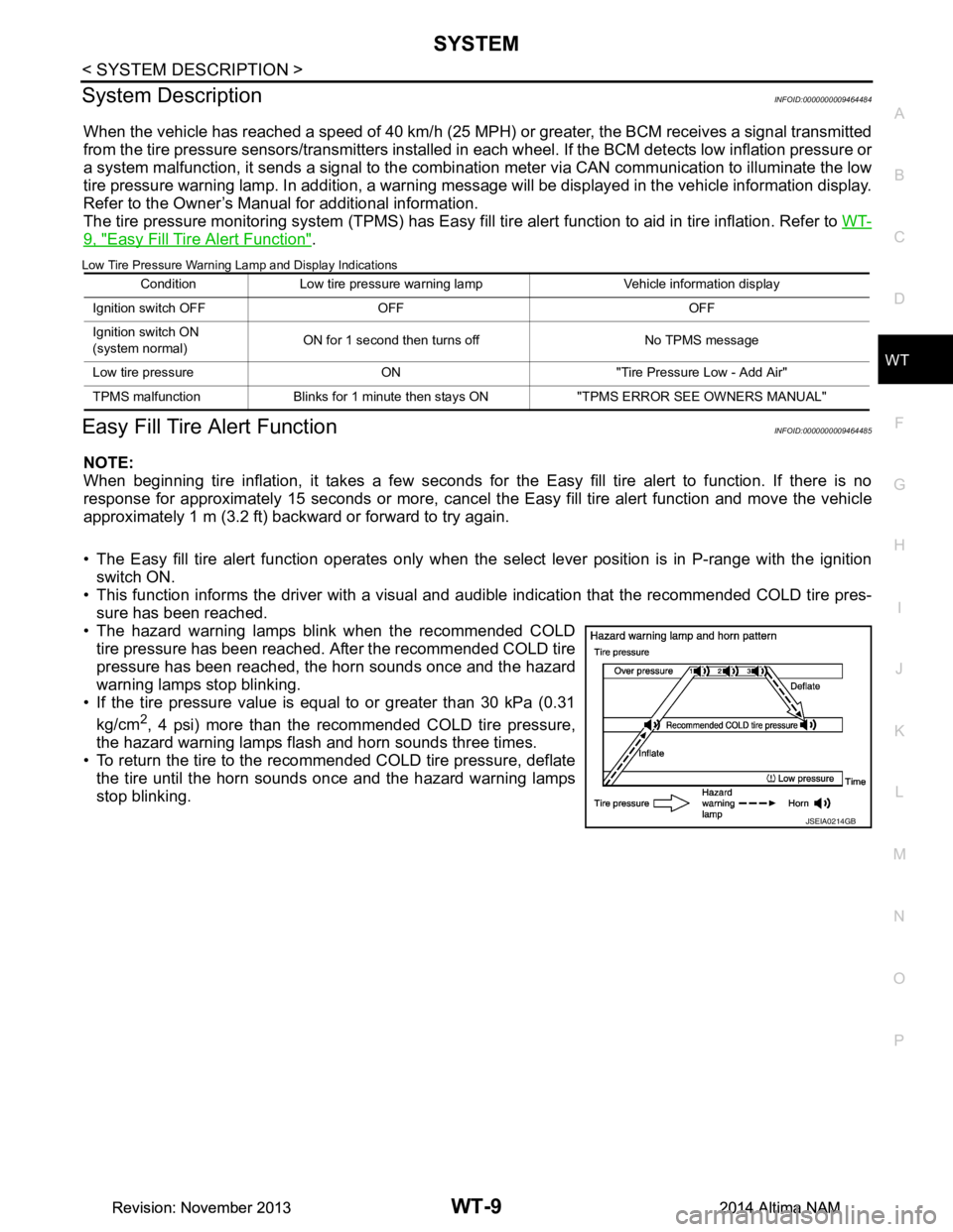
• This function informs the driver with a visual and audible indication that the recommended COLD tire pres-
sure has been reached.
• The hazard warning lamps blink when the recommended COLD tire pressure has been reached. After the recommended COLD tire
pressure has been reached, the horn sounds once and the hazard
warning lamps stop blinking.
• If the tire pressure value is equal to or greater than 30 kPa (0.31
kg/cm
2, 4 psi) more than the recommended COLD tire pressure,
the hazard warning lamps flash and horn sounds three times.
• To return the tire to the recommended COLD tire pressure, deflate
the tire until the horn sounds once and the hazard warning lamps
stop blinking.
Condition Low tire pressure warning lamp Vehicle information display
Ignition switch OFF OFF OFF
Ignition switch ON
(system normal) ON for 1 second then turns off No TPMS message
Low tire pressure ON "Tire Pressure Low - Add Air"
TPMS malfunction Blinks for 1 minute th en stays ON "TPMS ERROR SEE OWNERS MANUAL"
JSEIA0214GB
Revision: November 20132014 Altima NAMRevision: November 20132014 Altima NAM