2014 NISSAN TEANA keyless
[x] Cancel search: keylessPage 4705 of 4801
WT-30
< DTC/CIRCUIT DIAGNOSIS >
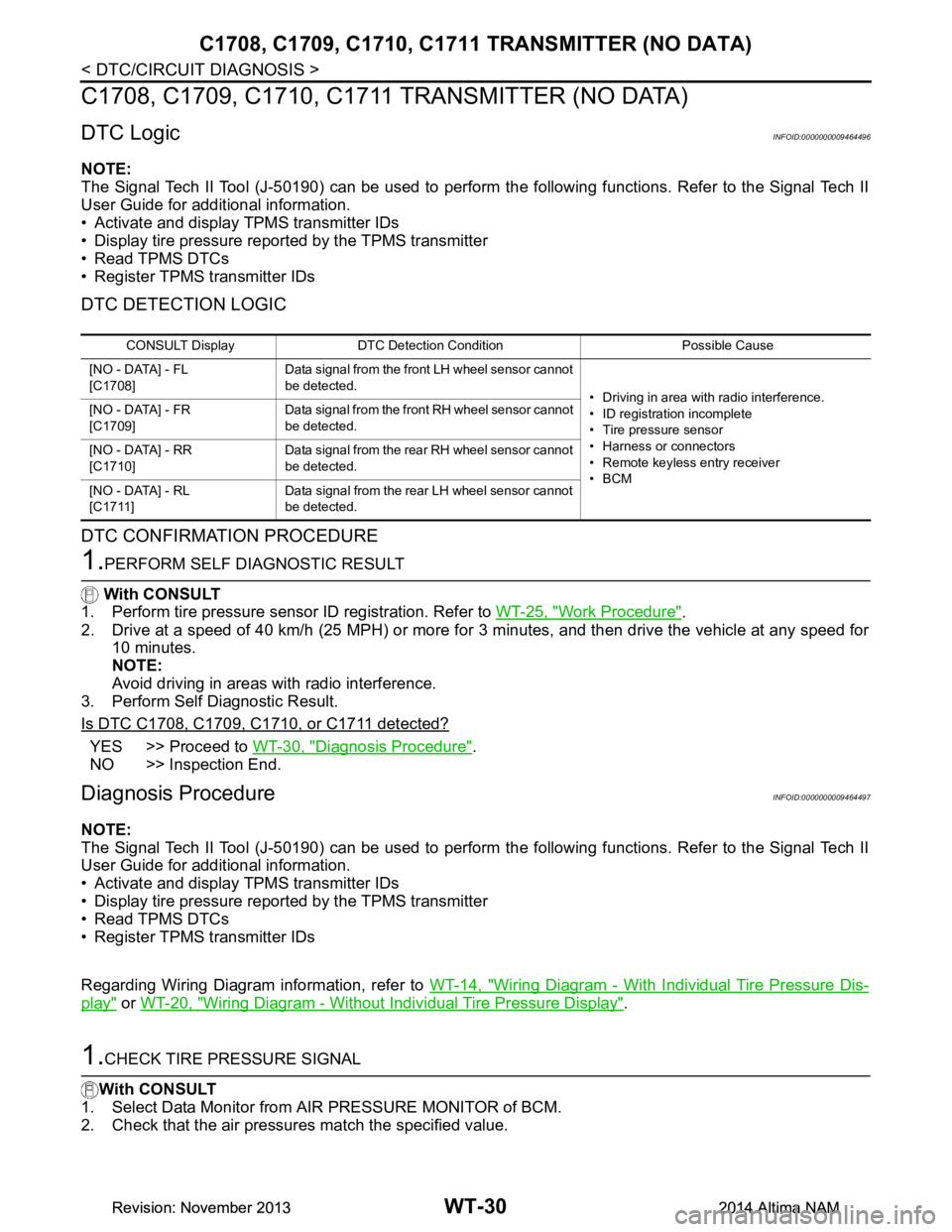
C1708, C1709, C1710, C1711 TRANSMITTER (NO DATA)
C1708, C1709, C1710, C1711 TRANSMITTER (NO DATA)
DTC LogicINFOID:0000000009464496
NOTE:
The Signal Tech II Tool (J-50190) can be used to perform the following functions. Refer to the Signal Tech II
User Guide for additional information.
• Activate and display TPMS transmitter IDs
• Display tire pressure reported by the TPMS transmitter
• Read TPMS DTCs
• Register TPMS transmitter IDs
DTC DETECTION LOGIC
DTC CONFIRMATION PROCEDURE
1.PERFORM SELF DIAGNOSTIC RESULT
With CONSULT
1. Perform tire pressure sensor ID registration. Refer to WT-25, "Work Procedure"
.
2. Drive at a speed of 40 km/h (25 MPH) or more fo r 3 minutes, and then drive the vehicle at any speed for
10 minutes.
NOTE:
Avoid driving in areas with radio interference.
3. Perform Self Diagnostic Result.
Is DTC C1708, C1709, C1710, or C1711 detected?
YES >> Proceed to WT-30, "Diagnosis Procedure".
NO >> Inspection End.
Diagnosis ProcedureINFOID:0000000009464497
NOTE:
The Signal Tech II Tool (J-50190) can be used to perform the following functions. Refer to the Signal Tech II
User Guide for additional information.
• Activate and display TPMS transmitter IDs
• Display tire pressure reported by the TPMS transmitter
• Read TPMS DTCs
• Register TPMS transmitter IDs
Regarding Wiring Diagram information, refer to WT-14, "Wiring Diagram - With Individual Tire Pressure Dis-
play" or WT-20, "Wiring Diagram - Without Individual Tire Pressure Display".
1.CHECK TIRE PRESSURE SIGNAL
With CONSULT
1. Select Data Monitor from AIR PRESSURE MONITOR of BCM.
2. Check that the air pressures match the specified value.
CONSULT Display DTC Detectio n Condition Possible Cause
[NO - DATA] - FL
[C1708] Data signal from the front LH wheel sensor cannot
be detected. • Driving in area with radio interference.
• ID registration incomplete
• Tire pressure sensor
• Harness or connectors
• Remote keyless entry receiver
•BCM
[NO - DATA] - FR
[C1709] Data signal from the front RH wheel sensor cannot
be detected.
[NO - DATA] - RR
[C1710] Data signal from the rear RH wheel sensor cannot
be detected.
[NO - DATA] - RL
[C1711] Data signal from the rear LH wheel sensor cannot
be detected.
Revision: November 20132014 Altima NAMRevision: November 20132014 Altima NAM
Page 4706 of 4801
C1708, C1709, C1710, C1711 TRANSMITTER (NO DATA)
WT-31
< DTC/CIRCUIT DIAGNOSIS >
C
D
F
G H
I
J
K L
M A
B
WT
N
O P
Are all tire pressures displayed 0 kPa (psi)?
YES >> GO TO 2.
NO >> Replace applicable tire pressure sensor. Refer to WT-57, "Removal and Installation"
.
2.CHECK REMOTE KEYLESS ENTRY RECEIVER POWER CIRCUIT
Check voltage between remote keyless entry receiver connector M27 terminal 1 and ground.
Is the inspection result normal?
YES >> GO TO 3.
NO >> Repair or replace harness or connectors.
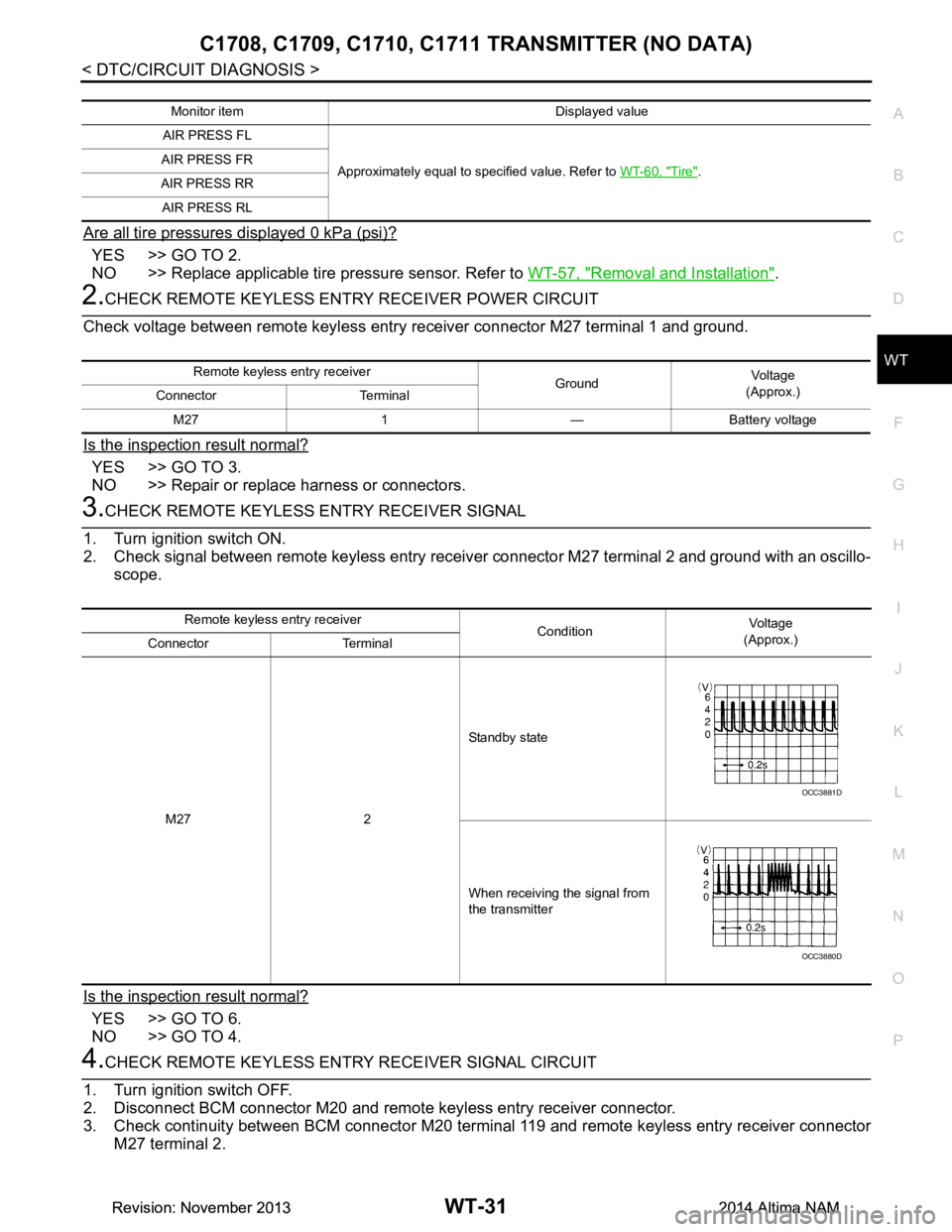
3.CHECK REMOTE KEYLESS ENTRY RECEIVER SIGNAL
1. Turn ignition switch ON.
2. Check signal between remote keyless entry receiver connector M27 terminal 2 and ground with an oscillo-
scope.
Is the inspection result normal?
YES >> GO TO 6.
NO >> GO TO 4.
4.CHECK REMOTE KEYLESS ENTR Y RECEIVER SIGNAL CIRCUIT
1. Turn ignition switch OFF.
2. Disconnect BCM connector M20 and remote keyless entry receiver connector.
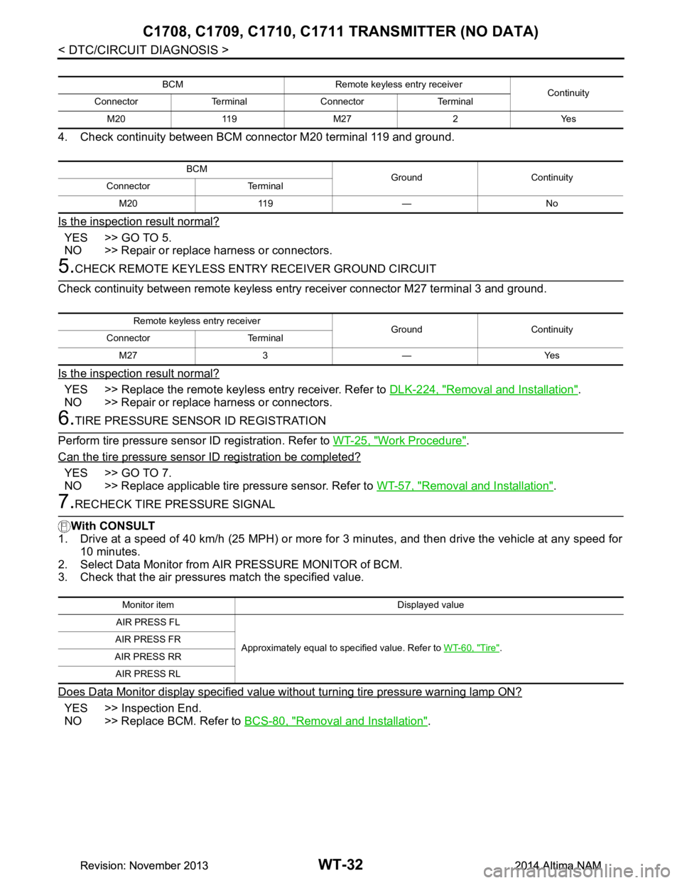
3. Check continuity between BCM connector M20 terminal 119 and remote keyless entry receiver connector
M27 terminal 2.
Monitor item Displayed value
AIR PRESS FL
Approximately equal to specified value. Refer to WT-60, "Tire"
.
AIR PRESS FR
AIR PRESS RR AIR PRESS RL
Remote keyless entry receiver GroundVo l ta g e
(Approx.)
Connector Terminal
M27 1 — Battery voltage
Remote keyless entry receiver ConditionVo l ta g e
(Approx.)
Connector Terminal
M27 2 Standby state
When receiving the signal from
the transmitter
OCC3881D
OCC3880D
Revision: November 20132014 Altima NAMRevision: November 20132014 Altima NAM
Page 4707 of 4801
WT-32
< DTC/CIRCUIT DIAGNOSIS >
C1708, C1709, C1710, C1711 TRANSMITTER (NO DATA)
4. Check continuity between BCM connector M20 terminal 119 and ground.
Is the inspection result normal?
YES >> GO TO 5.
NO >> Repair or replace harness or connectors.
5.CHECK REMOTE KEYL ESS ENTRY RECEIVER GROUND CIRCUIT
Check continuity between remote keyless entry receiver connector M27 terminal 3 and ground.
Is the inspection result normal?
YES >> Replace the remote keyless entry receiver. Refer to DLK-224, "Removal and Installation".
NO >> Repair or replace harness or connectors.
6.TIRE PRESSURE SENSOR ID REGISTRATION
Perform tire pressure sensor ID registration. Refer to WT-25, "Work Procedure"
.
Can the tire pressure sensor ID registration be completed?
YES >> GO TO 7.
NO >> Replace applicable tire pressure sensor. Refer to WT-57, "Removal and Installation"
.
7.RECHECK TIRE PRESSURE SIGNAL
With CONSULT
1. Drive at a speed of 40 km/h (25 MPH) or more fo r 3 minutes, and then drive the vehicle at any speed for
10 minutes.
2. Select Data Monitor from AIR PRESSURE MONITOR of BCM.
3. Check that the air pressures match the specified value.
Does Data Monitor display specified value without turning tire pressure warning lamp ON?
YES >> Inspection End.
NO >> Replace BCM. Refer to BCS-80, "Removal and Installation"
.
BCM Remote keyless entry receiver
Continuity
Connector Terminal Connector Terminal
M20 119 M27 2 Yes
BCM Ground Continuity
Connector Terminal
M20 119 — No
Remote keyless entry receiver Ground Continuity
Connector Terminal
M27 3 — Yes
Monitor item Displayed value
AIR PRESS FL
Approximately equal to specified value. Refer to WT-60, "Tire"
.
AIR PRESS FR
AIR PRESS RR AIR PRESS RL
Revision: November 20132014 Altima NAMRevision: November 20132014 Altima NAM
Page 4719 of 4801
WT-44
< DTC/CIRCUIT DIAGNOSIS >
C1734 BCM
C1734 BCM
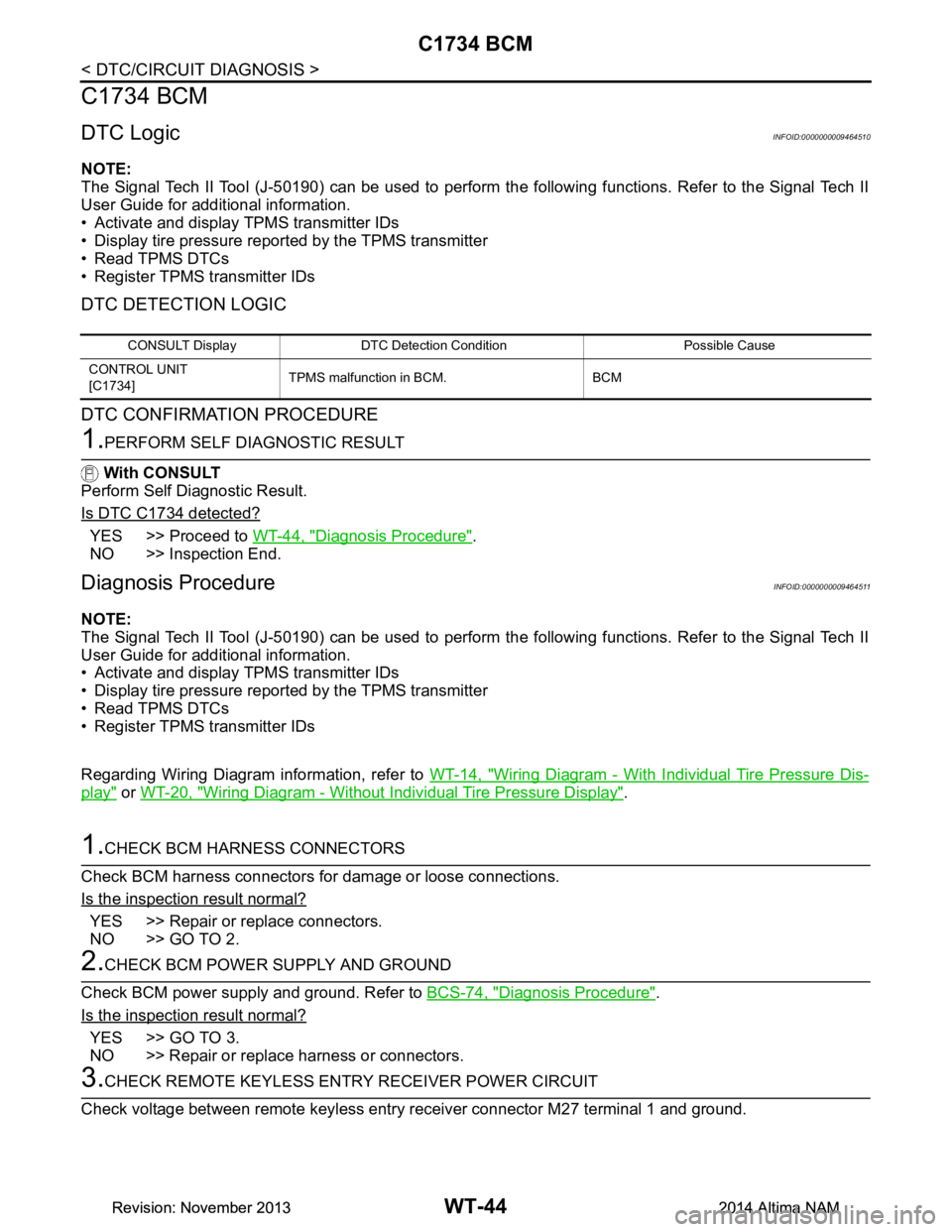
DTC LogicINFOID:0000000009464510
NOTE:
The Signal Tech II Tool (J-50190) can be used to perform the following functions. Refer to the Signal Tech II
User Guide for additional information.
• Activate and display TPMS transmitter IDs
• Display tire pressure reported by the TPMS transmitter
• Read TPMS DTCs
• Register TPMS transmitter IDs
DTC DETECTION LOGIC
DTC CONFIRMATION PROCEDURE
1.PERFORM SELF DIAGNOSTIC RESULT
With CONSULT
Perform Self Diagnostic Result.
Is DTC C1734 detected?
YES >> Proceed to WT-44, "Diagnosis Procedure".
NO >> Inspection End.
Diagnosis ProcedureINFOID:0000000009464511
NOTE:
The Signal Tech II Tool (J-50190) can be used to perform the following functions. Refer to the Signal Tech II
User Guide for additional information.
• Activate and display TPMS transmitter IDs
• Display tire pressure reported by the TPMS transmitter
• Read TPMS DTCs
• Register TPMS transmitter IDs
Regarding Wiring Diagram information, refer to WT-14, "Wiring Diagram - With Individual Tire Pressure Dis-
play" or WT-20, "Wiring Diagram - Without Individual Tire Pressure Display".
1.CHECK BCM HARNESS CONNECTORS
Check BCM harness connectors fo r damage or loose connections.
Is the inspection result normal?
YES >> Repair or replace connectors.
NO >> GO TO 2.
2.CHECK BCM POWER SUPPLY AND GROUND
Check BCM power supply and ground. Refer to BCS-74, "Diagnosis Procedure"
.
Is the inspection result normal?
YES >> GO TO 3.
NO >> Repair or replace harness or connectors.
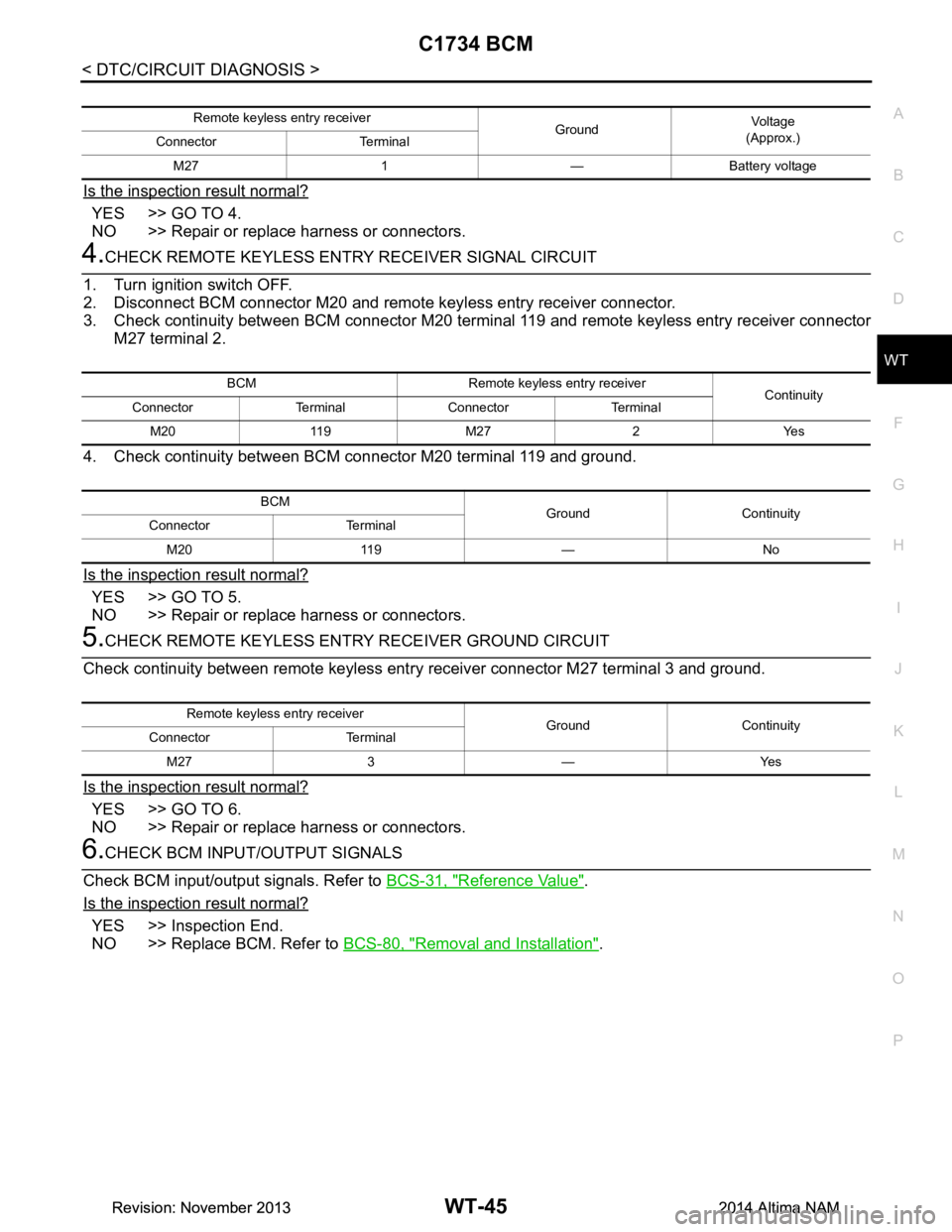
3.CHECK REMOTE KEYL ESS ENTRY RECEIVER POWER CIRCUIT
Check voltage between remote keyless entry receiver connector M27 terminal 1 and ground.
CONSULT Display DTC Detectio n Condition Possible Cause
CONTROL UNIT
[C1734] TPMS malfunction in BCM. BCM
Revision: November 20132014 Altima NAMRevision: November 20132014 Altima NAM
Page 4720 of 4801
C1734 BCMWT-45
< DTC/CIRCUIT DIAGNOSIS >
C
D
F
G H
I
J
K L
M A
B
WT
N
O P
Is the inspection result normal?
YES >> GO TO 4.
NO >> Repair or replace harness or connectors.
4.CHECK REMOTE KEYLESS ENTR Y RECEIVER SIGNAL CIRCUIT
1. Turn ignition switch OFF.
2. Disconnect BCM connector M20 and remote keyless entry receiver connector.
3. Check continuity between BCM connector M20 terminal 119 and remote keyless entry receiver connector
M27 terminal 2.
4. Check continuity between BCM connector M20 terminal 119 and ground.
Is the inspection result normal?
YES >> GO TO 5.
NO >> Repair or replace harness or connectors.
5.CHECK REMOTE KEYLESS ENTR Y RECEIVER GROUND CIRCUIT
Check continuity between remote keyless ent ry receiver connector M27 terminal 3 and ground.
Is the inspection result normal?
YES >> GO TO 6.
NO >> Repair or replace harness or connectors.
6.CHECK BCM INPUT/OUTPUT SIGNALS
Check BCM input/output signals. Refer to BCS-31, "Reference Value"
.
Is the inspection result normal?
YES >> Inspection End.
NO >> Replace BCM. Refer to BCS-80, "Removal and Installation"
.
Remote keyless entry receiver
GroundVo l ta g e
(Approx.)
Connector Terminal
M27 1 — Battery voltage
BCM Remote keyless entry receiver Continuity
Connector Terminal Connector Terminal
M20 119 M27 2 Yes
BCM Ground Continuity
Connector Terminal
M20 119 — No
Remote keyless entry receiver Ground Continuity
Connector Terminal
M27 3 — Yes
Revision: November 20132014 Altima NAMRevision: November 20132014 Altima NAM
Page 4729 of 4801

WT-54
< REMOVAL AND INSTALLATION >
REMOTE KEYLESS ENTRY RECEIVER
REMOVAL AND INSTALLATION
REMOTE KEYLESS ENTRY RECEIVER
Removal and InstallationINFOID:0000000009464521
The Tire Pressure Receiver is an integral part of the Remote Keyless Entry Receiver. Refer to DLK-224,
"Removal and Installation".
Revision: November 20132014 Altima NAMRevision: November 20132014 Altima NAM
Page 4745 of 4801

WW-10
< SYSTEM DESCRIPTION >
DIAGNOSIS SYSTEM (BCM)
DIAGNOSIS SYSTEM (BCM)
COMMON ITEM
COMMON ITEM : CONSULT Function (BCM - COMMON ITEM)INFOID:0000000009944151
CAUTION:
After disconnecting the CONSULT vehicle interface (VI) from the data link connector, the ignition must
be cycled OFF → ON (for at least 5 seconds) → OFF. If this step is not performed, the BCM may not go
to ”sleep mode”, potentially causing a di scharged battery and a no-start condition.
APPLICATION ITEM
CONSULT performs the following functions via CAN communication with BCM.
SYSTEM APPLICATION
BCM can perform the following functions.
Direct Diagnostic Mode Description
Ecu Identification The BCM part number is displayed.
Self Diagnostic Result The BCM self diagnostic results are displayed.
Data Monitor The BCM input/output data is displayed in real time.
Active Test The BCM activates outputs to test components.
Work support The settings for BCM functions can be changed.
Configuration • The vehicle specification can be read and saved.
• The vehicle specification can be written when replacing BCM.
CAN Diag Support Mntr The result of transmit/receive diagnosis of CAN communication is displayed.
System Sub System Direct Diagnostic Mode
Ecu Identification
Self Diagnostic Result
Data Monitor
Active Test
Work support
Configuration
CAN Diag Su pport Mntr
Door lock DOOR LOCK ××××
Rear window defogger REAR DEFOGGER ×××
Warning chime BUZZER ××
Interior room lamp timer INT LAMP ×××
Remote keyless entry system MULTI REMOTE ENT ×××
Exterior lamp HEADLAMP ×××
Wiper and washer WIPER ×××
Turn signal and hazard warning lamps FLASHER ××
Air conditioner AIR CONDITIONER ×
Intelligent Key system INTELLIGENT KEY ××××
Combination switch COMB SW ×
BCM BCM × × ×××
Immobilizer IMMU ×××
Interior room lamp battery saver BATTERY SAVER ××
Trunk open TRUNK ×
Vehicle security system THEFT ALM ×××
Revision: November 20132014 Altima NAMRevision: November 20132014 Altima NAM