2014 NISSAN QUEST sensor
[x] Cancel search: sensorPage 363 of 482
5-20Starting and driving
.Excessive noise (for example, audio
system volume, open vehicle win-
dow) will interfere with the chime
sound, and it may not be heard.
. The radar sensors may not be able to detect
and activate BSW when certain objects are
present such as:
— Pedestrians, bicycles, animals
— Several types of vehicles such as motor-
cycles
— Oncoming vehicles
— Vehicles remaining in the detection zone when you accelerate from a stop (See
“BSW driving situations” (P.5-20) .)
— A vehicle merging into an adjacent lane at a speed approximately the same as
your vehicle (See “BSW driving situa-
tions” (P.5-20) .)
— A vehicle approaching rapidly from be- hind. (See “BSW driving situations” (P.5-
20).)
— A vehicle which your vehicle overtakes rapidly. (See “BSW driving situations”
(P.5-20) .)
. Severe weather or road spray conditions
may reduce the ability of the radar to detect
other vehicles. .
The radar sensors detection zone is de-
signed based on a standard lane width.
When driving in a wider lane, the radar
sensors may not detect vehicles in an
adjacent lane. When driving in a narrow
lane, the radar sensors may detect vehicles
driving two lanes away.
. The radar sensors are designed to ignore
most stationary objects, however objects
such as guardrails, walls, foliage and parked
vehicles may occasionally be detected. This
is a normal operating condition.
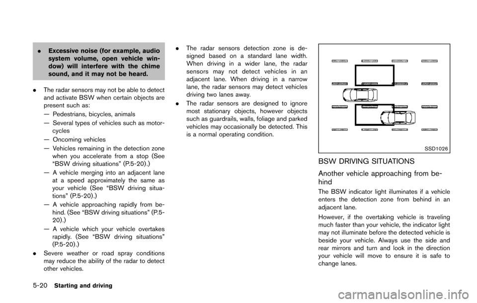
SSD1026
BSW DRIVING SITUATIONS
Another vehicle approaching from be-
hind
The BSW indicator light illuminates if a vehicle
enters the detection zone from behind in an
adjacent lane.
However, if the overtaking vehicle is traveling
much faster than your vehicle, the indicator light
may not illuminate before the detected vehicle is
beside your vehicle. Always use the side and
rear mirrors and turn and look in the direction
your vehicle will move to ensure it is safe to
change lanes.
Page 364 of 482
SSD1031
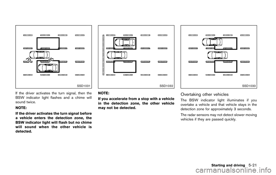
If the driver activates the turn signal, then the
BSW indicator light flashes and a chime will
sound twice.
NOTE:
If the driver activates the turn signal before
a vehicle enters the detection zone, the
BSW indicator light will flash but no chime
will sound when the other vehicle is
detected.
SSD1032
NOTE:
If you accelerate from a stop with a vehicle
in the detection zone, the other vehicle
may not be detected.
SSD1033
Overtaking other vehicles
The BSW indicator light illuminates if you
overtake a vehicle and that vehicle stays in the
detection zone for approximately 3 seconds.
The radar sensors may not detect slower moving
vehicles if they are passed quickly.
Starting and driving5-21
Page 366 of 482
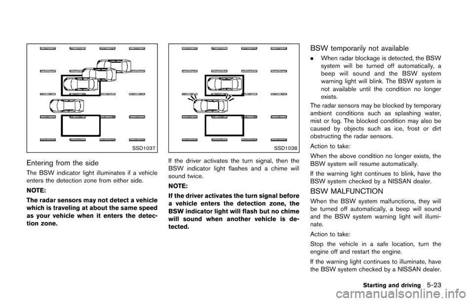
SSD1037
Entering from the side
The BSW indicator light illuminates if a vehicle
enters the detection zone from either side.
NOTE:
The radar sensors may not detect a vehicle
which is traveling at about the same speed
as your vehicle when it enters the detec-
tion zone.
SSD1038
If the driver activates the turn signal, then the
BSW indicator light flashes and a chime will
sound twice.
NOTE:
If the driver activates the turn signal before
a vehicle enters the detection zone, the
BSW indicator light will flash but no chime
will sound when another vehicle is de-
tected.
BSW temporarily not available
.When radar blockage is detected, the BSW
system will be turned off automatically, a
beep will sound and the BSW system
warning light will blink. The BSW system is
not available until the condition no longer
exists.
The radar sensors may be blocked by temporary
ambient conditions such as splashing water,
mist or fog. The blocked condition may also be
caused by objects such as ice, frost or dirt
obstructing the radar sensors.
Action to take:
When the above condition no longer exists, the
BSW system will resume automatically.
If the warning light continues to blink, have the
BSW system checked by a NISSAN dealer.
BSW MALFUNCTION
When the BSW system malfunctions, they will
be turned off automatically, a beep will sound
and the BSW system warning light will illumi-
nate.
Action to take:
Stop the vehicle in a safe location, turn the
engine off and restart the engine.
If the warning light continues to illuminate, have
the BSW system checked by a NISSAN dealer.
Starting and driving5-23
Page 367 of 482
5-24Starting and driving
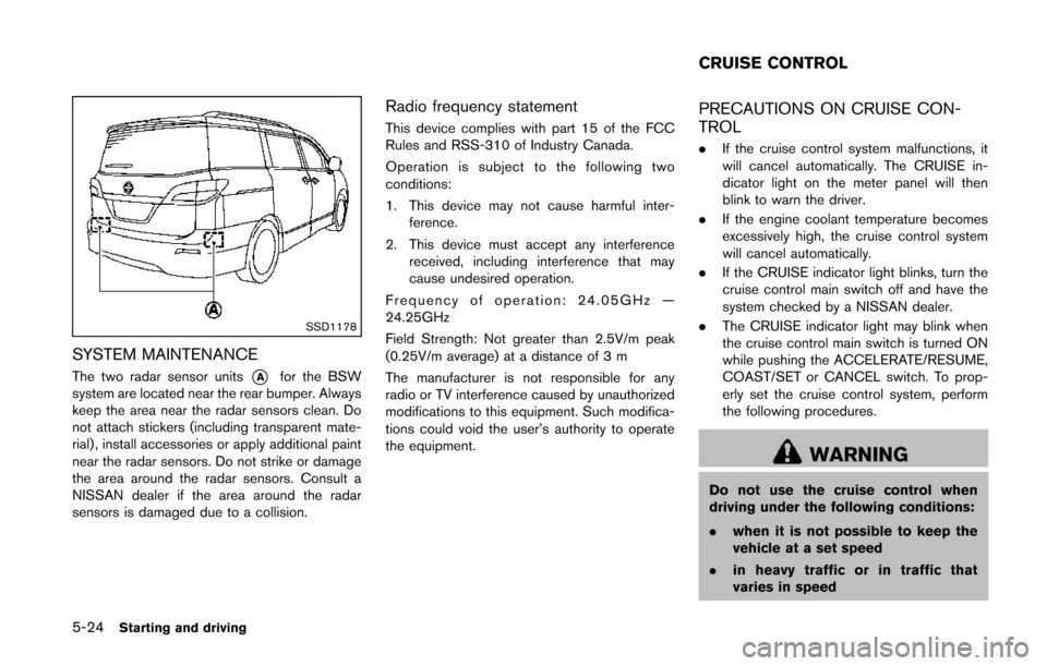
SSD1178
SYSTEM MAINTENANCE
The two radar sensor units*Afor the BSW
system are located near the rear bumper. Always
keep the area near the radar sensors clean. Do
not attach stickers (including transparent mate-
rial) , install accessories or apply additional paint
near the radar sensors. Do not strike or damage
the area around the radar sensors. Consult a
NISSAN dealer if the area around the radar
sensors is damaged due to a collision.
Radio frequency statement
This device complies with part 15 of the FCC
Rules and RSS-310 of Industry Canada.
Operation is subject to the following two
conditions:
1. This device may not cause harmful inter- ference.
2. This device must accept any interference received, including interference that may
cause undesired operation.
Frequency of operation: 24.05GHz —
24.25GHz
Field Strength: Not greater than 2.5V/m peak
(0.25V/m average) at a distance of 3 m
The manufacturer is not responsible for any
radio or TV interference caused by unauthorized
modifications to this equipment. Such modifica-
tions could void the user’s authority to operate
the equipment.
PRECAUTIONS ON CRUISE CON-
TROL
. If the cruise control system malfunctions, it
will cancel automatically. The CRUISE in-
dicator light on the meter panel will then
blink to warn the driver.
. If the engine coolant temperature becomes
excessively high, the cruise control system
will cancel automatically.
. If the CRUISE indicator light blinks, turn the
cruise control main switch off and have the
system checked by a NISSAN dealer.
. The CRUISE indicator light may blink when
the cruise control main switch is turned ON
while pushing the ACCELERATE/RESUME,
COAST/SET or CANCEL switch. To prop-
erly set the cruise control system, perform
the following procedures.
WARNING
Do not use the cruise control when
driving under the following conditions:
. when it is not possible to keep the
vehicle at a set speed
. in heavy traffic or in traffic that
varies in speed
CRUISE CONTROL
Page 374 of 482
Self-test feature
The ABS includes electronic sensors, electric
pumps, hydraulic solenoids and a computer. The
computer has a built-in diagnostic feature that
tests the system each time you start the engine
and move the vehicle at a low speed in forward
or reverse. When the self-test occurs, you may
hear a “clunk” noise and/or feel a pulsation in the
brake pedal. This is normal and does not
indicate a malfunction. If the computer senses
a malfunction, it switches the ABS off and
illuminates the ABS warning light on the
instrument panel. The brake system then oper-
ates normally, but without anti-lock assistance.
If the ABS warning light illuminates during the
self-test or while driving, have the vehicle
checked by a NISSAN dealer.
Normal operation
The ABS operates at speeds above 3 to 6 MPH
(5 to 10 km/h). The speed varies according to
road conditions.
When the ABS senses that one or more wheels
are close to locking up, the actuator rapidly
applies and releases hydraulic pressure. This
action is similar to pumping the brakes very
quickly. You may feel a pulsation in the brake
pedal and hear a noise from under the hood or
feel a vibration from the actuator when it isoperating. This is normal and indicates that the
ABS is operating properly. However, the pulsa-
tion may indicate that road conditions are
hazardous and extra care is required while
driving.
The Vehicle Dynamic Control (VDC) system
uses various sensors to monitor driver inputs
and vehicle motion. Under certain driving con-
ditions, the VDC system helps to perform the
following functions.
.
Controls brake pressure to reduce wheel
slip on one slipping drive wheel so power is
transferred to a non slipping drive wheel on
the same axle.
. Controls brake pressure and engine output
to reduce drive wheel slip based on vehicle
speed (traction control function) .
. Controls brake pressure at individual wheels
and engine output to help the driver maintain
control of the vehicle in the following
conditions:
— understeer (vehicle tends to not follow
the steered path despite increased
steering input)
— oversteer (vehicle tends to spin due to certain road or driving conditions) .
The VDC system can help the driver to maintain
control of the vehicle, but it cannot prevent loss
of vehicle control in all driving situations.
When the VDC system operates, the VDC
warning light
in the instrument panel flashes
so note the following:
. The road may be slippery or the system may
determine some action is required to help
Starting and driving5-31
VEHICLE DYNAMIC CONTROL (VDC)
SYSTEM
Page 382 of 482
TIRE PRESSURE MONITORING SYS-
TEM (TPMS)
This vehicle is equipped with the Tire Pressure
Monitoring System (TPMS) . It monitors tire
pressure of all tires except the spare. When
the low tire pressure warning light is lit and the
CHECK TIRE PRESSURE warning appears on
the dot matrix liquid crystal display, one or more
of your tires is significantly under-inflated. If the
vehicle is being driven with low tire pressure, the
TPMS will activate and warn you of it by the low
tire pressure warning light. This system will
activate only when the vehicle is driven at
speeds above 16 MPH (25 km/h). For more
details, see “Warning/indicator lights and audi-
ble reminders” (P.2-11) and “Tire Pressure
Monitoring System (TPMS)” (P.5-3) .
WARNING
.If the low tire pressure warning light
illuminates while driving, avoid sud-
den steering maneuvers or abrupt
braking, reduce vehicle speed, pull
off the road to a safe location and
stop the vehicle as soon as possi-
ble. Driving with under-inflated tires
may permanently damage the tires
and increase the likelihood of tire failure. Serious vehicle damage
could occur and may lead to an
accident and could result in serious
personal injury. Check the tire pres-
sure for all four tires. Adjust the tire
pressure to the recommended COLD
tire pressure shown on the Tire and
Loading Information label to turn
the low tire pressure warning light
OFF. If the light still illuminates
while driving after adjusting the tire
pressure, a tire may be flat. If you
have a flat tire, replace it with a
spare tire as soon as possible.
. When a spare tire is mounted or a
wheel is replaced, the TPMS will not
function and the low tire pressure
warning light will flash for approxi-
mately 1 minute. The light will
remain on after 1 minute. Contact
your NISSAN dealer as soon as
possible for tire replacement and/
or system resetting.
. Replacing tires with those not ori-
ginally specified by NISSAN could
affect the proper operation of the
TPMS.
. Do not inject any tire liquid or
aerosol tire sealant into the tires, as this may cause a malfunction of
the tire pressure sensors.
CHANGING A FLAT TIRE
If you have a flat tire, follow the instructions
below.
Stopping the vehicle
1. Safely move the vehicle off the road and
away from traffic.
2. Turn on the hazard warning flashers.
3. Park on a level surface and apply the parking brake. Move the shift lever to the P (Park)
position.
4. Turn off the engine.
5. Raise the hood to warn other traffic, and to signal professional road assistance person-
nel that you need assistance.
6. Have all passengers get out of the vehicle and stand in a safe place, away from traffic
and clear of the vehicle.
WARNING
. Make sure the parking brake is
securely applied and the transmis-
sion is shifted into the P (Park)
position.
In case of emergency6-3
FLAT TIRE
Page 401 of 482
7-4Appearance and care
TIRE DRESSING
NISSAN does not recommend the use of tire
dressings. Tire manufacturers apply a coating to
the tires to help reduce discoloration of the
rubber. If a tire dressing is applied to the tires, it
may react with the coating and form a com-
pound. This compound may come off the tire
while driving and stain the vehicle paint.
If you choose to use a tire dressing, take the
following precautions:
.Use a water-based tire dressing. The coat-
ing on the tire dissolves more easily with an
oil-based tire dressing.
. Apply a light coat of tire dressing to help
prevent it from entering the tire tread/
grooves (where it would be difficult to
remove) .
. Wipe off excess tire dressing using a dry
towel. Make sure the tire dressing is
completely removed from the tire tread/
grooves.
. Allow the tire dressing to dry as recom-
mended by tire dressing manufacturer. Occasionally remove loose dust from the interior
trim, plastic parts and seats using a vacuum
cleaner or soft bristled brush. Wipe the vinyl and
leather surfaces with a clean, soft cloth dam-
pened in mild soap solution, then wipe clean
with a dry soft cloth.
Regular care and cleaning is required in order to
maintain the appearance of the leather.
Before using any fabric protector, read the
manufacturer’s recommendations. Some fabric
protectors contain chemicals that may stain or
bleach the seat material.
Use a cloth dampened only with water, to clean
the meter and gauge lens.
WARNING
Do not use water or acidic cleaners (hot
steam cleaners) on the seat. This can
damage the seat or occupant classifica-
tion sensor. This can also affect the
operation of the air bag system and
result in serious personal injury.
CAUTION
.
Never use benzine, thinner, or any
similar material.
. For cleaning, use a soft cloth, dam-
pened with water. Never use a rough
cloth, alcohol, benzine, thinner or
any kind of solvent or paper towel
with a chemical cleaning agent.
They will scratch or cause discolora-
tion to the lens.
. Do not spray any liquid such as
water on the meter lens. Spraying
liquid may cause the system to
malfunction.
. Small dirt particles can be abrasive
and damaging to the leather sur-
faces and should be removed
promptly. Do not use saddle soap,
car waxes, polishes, oils, cleaning
fluids, solvents, detergents or am-
monia-based cleaners as they may
damage the leather’s natural finish.
. Never use fabric protectors unless
recommended by the manufacturer.
. Do not use glass or plastic cleaner
on meter or gauge lens covers. It
CLEANING INTERIOR