2014 NISSAN QUEST battery
[x] Cancel search: batteryPage 158 of 482
SPA2074
INTELLIGENT KEY OPERATING
RANGE
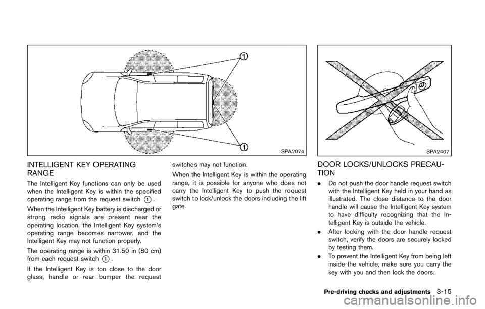
The Intelligent Key functions can only be used
when the Intelligent Key is within the specified
operating range from the request switch
*1.
When the Intelligent Key battery is discharged or
strong radio signals are present near the
operating location, the Intelligent Key system’s
operating range becomes narrower, and the
Intelligent Key may not function properly.
The operating range is within 31.50 in (80 cm)
from each request switch
*1.
If the Intelligent Key is too close to the door
glass, handle or rear bumper the request switches may not function.
When the Intelligent Key is within the operating
range, it is possible for anyone who does not
carry the Intelligent Key to push the request
switch to lock/unlock the doors including the lift
gate.
SPA2407
DOOR LOCKS/UNLOCKS PRECAU-
TION
.
Do not push the door handle request switch
with the Intelligent Key held in your hand as
illustrated. The close distance to the door
handle will cause the Intelligent Key system
to have difficulty recognizing that the In-
telligent Key is outside the vehicle.
. After locking with the door handle request
switch, verify the doors are securely locked
by testing them.
. To prevent the Intelligent Key from being left
inside the vehicle, make sure you carry the
key with you and then lock the doors.
Pre-driving checks and adjustments3-15
Page 162 of 482
LOCK button on the Intelligent Key after the
door is closed. (See “Remote keyless entry
system” (P.3-21) .)
BATTERY SAVER SYSTEM
When all the following conditions are met for a
period of time, the battery saver system will cut
off the power supply to prevent battery dis-
charge.
.The ignition switch is in the ACC position,
and
. All doors are closed, and
. The shift lever is in the P (Park) position.
WARNING SIGNALS
To help prevent the vehicle from moving
unexpectedly by erroneous operation of the
Intelligent Key listed on the following chart or
to help prevent the vehicle from being stolen,
chime or beep sounds inside and outside the
vehicle and a warning displays in the dot matrix
liquid crystal display.
When a chime or beep sounds or the warning
displays, be sure to check the vehicle and
Intelligent Key.
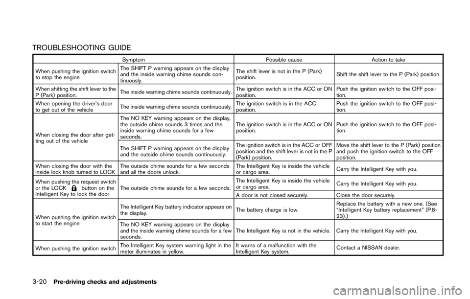
See “Troubleshooting guide” (P.3-20) and “Dot
matrix liquid crystal display” (P.2-18).
Pre-driving checks and adjustments3-19
Page 163 of 482
3-20Pre-driving checks and adjustments
TROUBLESHOOTING GUIDE
SymptomPossible causeAction to take
When pushing the ignition switch
to stop the engine The SHIFT P warning appears on the display
and the inside warning chime sounds con-
tinuously.
The shift lever is not in the P (Park)
position.
Shift the shift lever to the P (Park) position.
When shifting the shift lever to the
P (Park) position. The inside warning chime sounds continuously.
The ignition switch is in the ACC or ON
position.Push the ignition switch to the OFF posi-
tion.
When opening the driver’s door
to get out of the vehicle The inside warning chime sounds continuously. The ignition switch is in the ACC
position.Push the ignition switch to the OFF posi-
tion.
When closing the door after get-
ting out of the vehicle The NO KEY warning appears on the display,
the outside chime sounds 3 times and the
inside warning chime sounds for a few
seconds.
The ignition switch is in the ACC or ON
position.
Push the ignition switch to the OFF posi-
tion.
The SHIFT P warning appears on the display
and the outside chime sounds continuously. The ignition switch is in the ACC or OFF
position and the shift lever is not in the P
(Park) position.Move the shift lever to the P (Park) position
and push the ignition switch to the OFF
position.
When closing the door with the
inside lock knob turned to LOCK The outside chime sounds for a few seconds
and all the doors unlock. The Intelligent Key is inside the vehicle
or cargo area.
Carry the Intelligent Key with you.
When pushing the request switch
or the LOCK
button on the
Intelligent Key to lock the door The outside chime sounds for a few seconds. The Intelligent Key is inside the vehicle
or cargo area.
Carry the Intelligent Key with you.
A door is not closed securely. Close the door securely.
When pushing the ignition switch
to start the engine The Intelligent Key battery indicator appears on
the display.
The battery charge is low.Replace the battery with a new one. (See
“Intelligent Key battery replacement” (P.8-
23).)
The NO KEY warning appears on the display
and the inside warning chime sounds for a few
seconds. The Intelligent Key is not in the vehicle. Carry the Intelligent Key with you.
When pushing the ignition switch The Intelligent Key system warning light in the
meter illuminates in yellow. It warns of a malfunction with the
Intelligent Key system.
Contact a NISSAN dealer.
Page 164 of 482
WARNING
The Intelligent Key transmits radio
waves when the buttons are pushed.
The FAA advises that radio waves may
affect aircraft navigation and commu-
nication systems. Do not operate the
Intelligent Key while on an airplane.
Make sure the buttons are not operated
unintentionally when the unit is stored
for a flight.
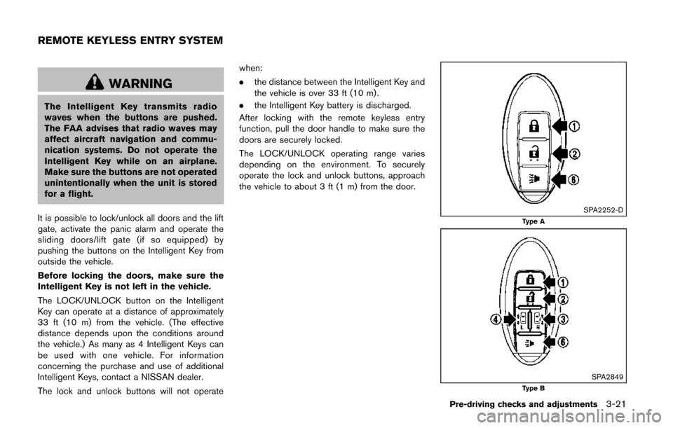
It is possible to lock/unlock all doors and the lift
gate, activate the panic alarm and operate the
sliding doors/lift gate (if so equipped) by
pushing the buttons on the Intelligent Key from
outside the vehicle.
Before locking the doors, make sure the
Intelligent Key is not left in the vehicle.
The LOCK/UNLOCK button on the Intelligent
Key can operate at a distance of approximately
33 ft (10 m) from the vehicle. (The effective
distance depends upon the conditions around
the vehicle.) As many as 4 Intelligent Keys can
be used with one vehicle. For information
concerning the purchase and use of additional
Intelligent Keys, contact a NISSAN dealer.
The lock and unlock buttons will not operate when:
.
the distance between the Intelligent Key and
the vehicle is over 33 ft (10 m) .
. the Intelligent Key battery is discharged.
After locking with the remote keyless entry
function, pull the door handle to make sure the
doors are securely locked.
The LOCK/UNLOCK operating range varies
depending on the environment. To securely
operate the lock and unlock buttons, approach
the vehicle to about 3 ft (1 m) from the door.
SPA2252-DType A
SPA2849Type B
Pre-driving checks and adjustments3-21
REMOTE KEYLESS ENTRY SYSTEM
Page 169 of 482
3-26Pre-driving checks and adjustments
WARNING
.Always be sure the lift gate has
been closed securely to prevent it
from opening while driving.
. Do not drive with the lift gate open.
This could allow dangerous exhaust
gases to be drawn into the vehicle.
See “Exhaust gas (carbon monox-
ide)” (P.5-2) of this manual.
. Do not leave children unattended
inside the vehicle. They could un-
knowingly activate switches or con-
trols. Unattended children could
become involved in serious acci-
dents.
. Always be sure that hands and feet
are clear of the gate frame to avoid
injury while closing the lift gate.
SPA2881
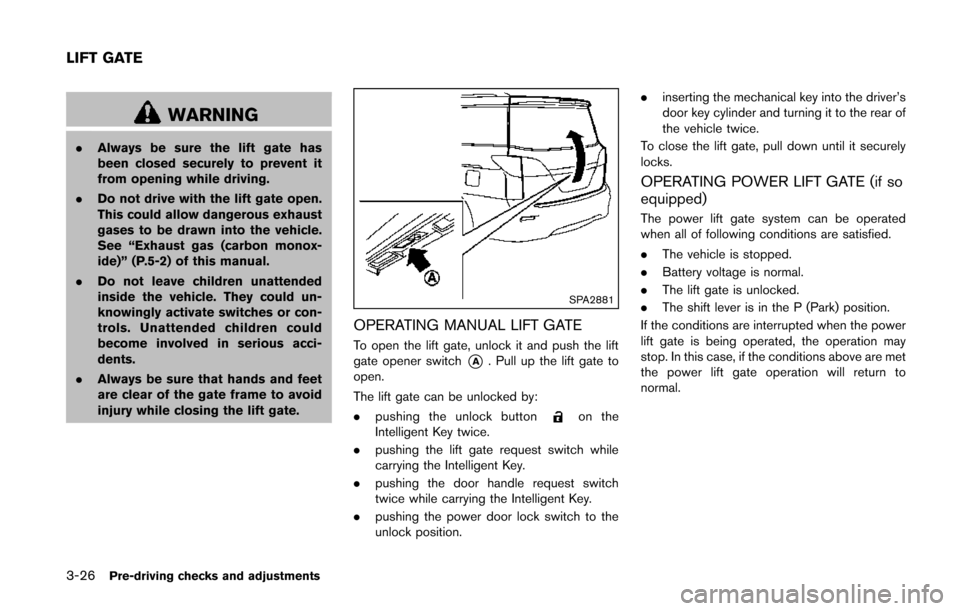
OPERATING MANUAL LIFT GATE
To open the lift gate, unlock it and push the lift
gate opener switch
*A. Pull up the lift gate to
open.
The lift gate can be unlocked by:
. pushing the unlock button
on the
Intelligent Key twice.
. pushing the lift gate request switch while
carrying the Intelligent Key.
. pushing the door handle request switch
twice while carrying the Intelligent Key.
. pushing the power door lock switch to the
unlock position. .
inserting the mechanical key into the driver’s
door key cylinder and turning it to the rear of
the vehicle twice.
To close the lift gate, pull down until it securely
locks.
OPERATING POWER LIFT GATE (if so
equipped)
The power lift gate system can be operated
when all of following conditions are satisfied.
. The vehicle is stopped.
. Battery voltage is normal.
. The lift gate is unlocked.
. The shift lever is in the P (Park) position.
If the conditions are interrupted when the power
lift gate is being operated, the operation may
stop. In this case, if the conditions above are met
the power lift gate operation will return to
normal.
LIFT GATE
Page 171 of 482
3-28Pre-driving checks and adjustments
Power open
When the lift gate is fully closed, the lift gate will
fully open automatically by:
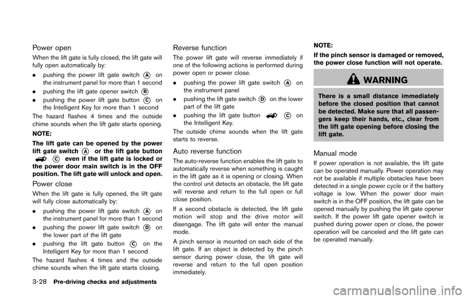
.pushing the power lift gate switch
*Aon
the instrument panel for more than 1 second
. pushing the lift gate opener switch
*B
.pushing the power lift gate button*Con
the Intelligent Key for more than 1 second
The hazard flashes 4 times and the outside
chime sounds when the lift gate starts opening.
NOTE:
The lift gate can be opened by the power
lift gate switch
*Aor the lift gate button
*Ceven if the lift gate is locked or
the power door main switch is in the OFF
position. The lift gate will unlock and open.
Power close
When the lift gate is fully opened, the lift gate
will fully close automatically by:
. pushing the power lift gate switch
*Aon
the instrument panel for more than 1 second
. pushing the power lift gate switch
*Don
the lower part of the lift gate
. pushing the lift gate button
*Con the
Intelligent Key for more than 1 second
The hazard flashes 4 times and the outside
chime sounds when the lift gate starts closing.
Reverse function
The power lift gate will reverse immediately if
one of the following actions is performed during
power open or power close.
. pushing the power lift gate switch
*Aon
the instrument panel
. pushing the lift gate switch
*Don the lower
part of the lift gate
. pushing the lift gate button
*Con
the Intelligent Key.
The outside chime sounds when the lift gate
starts to reverse.
Auto reverse function
The auto-reverse function enables the lift gate to
automatically reverse when something is caught
in the lift gate as it is opening or closing. When
the control unit detects an obstacle, the lift gate
will reverse and return to the full open or full
close position.
If a second obstacle is detected, the lift gate
motion will stop and the drive motor will
disengage. The lift gate will enter the manual
mode.
A pinch sensor is mounted on each side of the
lift gate. If an object is detected by the pinch
sensor during power close, the lift gate will
reverse and return to the full open position
immediately. NOTE:
If the pinch sensor is damaged or removed,
the power close function will not operate.
WARNING
There is a small distance immediately
before the closed position that cannot
be detected. Make sure that all passen-
gers keep their hands, etc., clear from
the lift gate opening before closing the
lift gate.
Manual mode
If power operation is not available, the lift gate
can be operated manually. Power operation may
not be available if multiple obstacles have been
detected in a single power cycle or if the battery
voltage is low. When the power door main
switch is in the OFF position, the lift gate can be
opened manually by pushing the lift gate opener
switch. If the power lift gate opener switch is
pushed during power open or close, the power
operation will be canceled and the lift gate can
be operated manually.
Page 173 of 482
3-30Pre-driving checks and adjustments
SPA2824
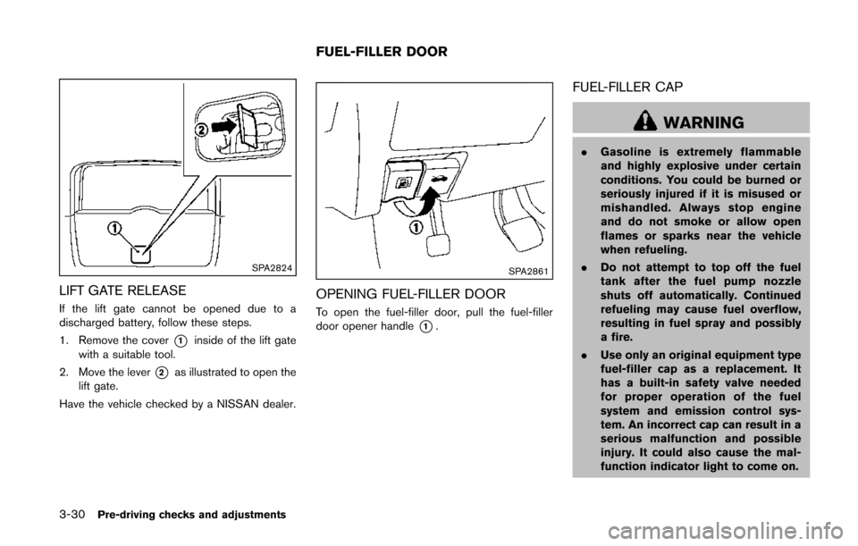
LIFT GATE RELEASE
If the lift gate cannot be opened due to a
discharged battery, follow these steps.
1. Remove the cover
*1inside of the lift gate
with a suitable tool.
2. Move the lever
*2as illustrated to open the
lift gate.
Have the vehicle checked by a NISSAN dealer.
SPA2861
OPENING FUEL-FILLER DOOR
To open the fuel-filler door, pull the fuel-filler
door opener handle
*1.
FUEL-FILLER CAP
WARNING
. Gasoline is extremely flammable
and highly explosive under certain
conditions. You could be burned or
seriously injured if it is misused or
mishandled. Always stop engine
and do not smoke or allow open
flames or sparks near the vehicle
when refueling.
. Do not attempt to top off the fuel
tank after the fuel pump nozzle
shuts off automatically. Continued
refueling may cause fuel overflow,
resulting in fuel spray and possibly
a fire.
. Use only an original equipment type
fuel-filler cap as a replacement. It
has a built-in safety valve needed
for proper operation of the fuel
system and emission control sys-
tem. An incorrect cap can result in a
serious malfunction and possible
injury. It could also cause the mal-
function indicator light to come on.
FUEL-FILLER DOOR
Page 180 of 482
The automatic drive positioner system has two
features:
.Entry/exit function
. Memory storage
ENTRY/EXIT FUNCTION
This system is designed so that the driver’s seat
will automatically move when the shift lever is in
the P (Park) position. This allows the driver to
get into and out of the driver’s seat more easily.
The driver’s seat will slide backward when the
driver’s door is opened with the ignition switch
in the LOCK position.
The driver’s seat will return to the previous
positions when the ignition switch is pushed to
the ACC position.
The driver’s seat will not return to the previous
positions if the seat adjusting switch is operated
when the seat is at the exit position.
Cancel or activate entry/exit function
The shift lever must be in the P (Park) position
with the ignition switch in the OFF position.
The entry/exit function can be activated or
canceled by pressing and holding the SET
switch for more than 10 seconds.
The indicator lights on the memory switches (1
and 2) will blink once when the function is
canceled, and the indicator lights will blink twice when the function is activated. Note that the
indicator lights may illuminate after 5 seconds
while holding the SET switch. This indicates
readiness for linking the Intelligent Key to a
stored memory position. Keep the SET switch
pressed for more than 10 seconds to turn on or
off the entry/exit function.
The entry/exit function can also be activated or
canceled if the “Slide Driver Seat Back on Exit”
key is turned to ON or OFF in the “Comfort”
settings. (See “Vehicle information and settings
(models with center multi-function control pa-
nel)” (P.4-8) .)
Initialize entry/exit function
If the battery cable is disconnected, or if the fuse
opens, the entry/exit function will not work
though this function was set on before. In such
a case, after connecting the battery or replacing
with a new fuse, open and close the driver’s
door more than two times after the ignition
switch is placed in the LOCK position from the
ON position. The entry/exit function will be
activated.
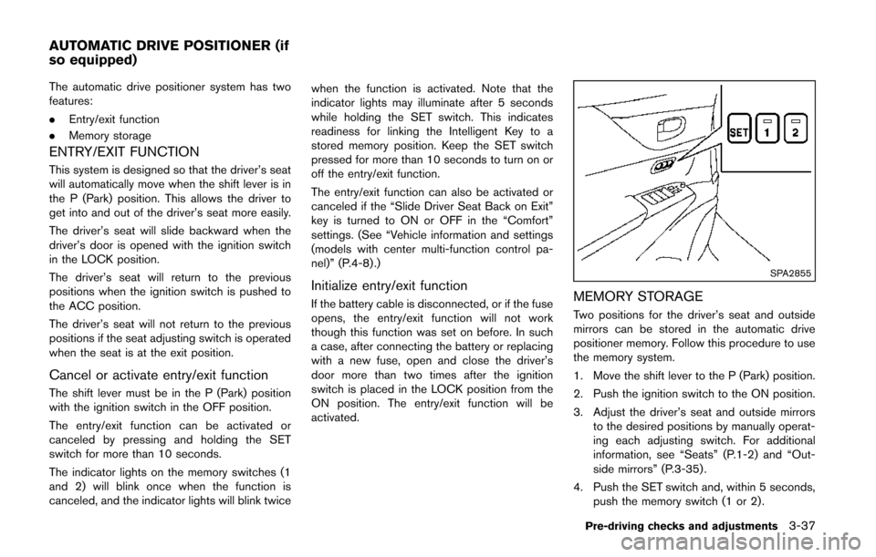
SPA2855
MEMORY STORAGE
Two positions for the driver’s seat and outside
mirrors can be stored in the automatic drive
positioner memory. Follow this procedure to use
the memory system.
1. Move the shift lever to the P (Park) position.
2. Push the ignition switch to the ON position.
3. Adjust the driver’s seat and outside mirrors
to the desired positions by manually operat-
ing each adjusting switch. For additional
information, see “Seats” (P.1-2) and “Out-
side mirrors” (P.3-35) .
4. Push the SET switch and, within 5 seconds, push the memory switch (1 or 2) .
Pre-driving checks and adjustments3-37
AUTOMATIC DRIVE POSITIONER (if
so equipped)