2014 NISSAN QUEST headrest
[x] Cancel search: headrestPage 56 of 482
2. Position the child restraint on the seat.Always follow the child restraint manufac-
turer’s instructions.
The back of the child restraint should be
secured against the vehicle seatback.
If necessary, adjust or remove the head
restraint or headrest to obtain the correct
child restraint fit. If the head restraint or
headrest is removed, store it in a secure
place. Be sure to reinstall the head
restraint or headrest when the child
restraint is removed. See “Head re-
straints/headrests” (P.1-10) for head re-
straint or headrest adjustment, removal and
installation information.
If the seating position does not have an
adjustable head restraint or headrest and it
is interfering with the proper child restraint
fit, try another seating position or a different
child restraint.
SSS0360BForward-facing — step 3
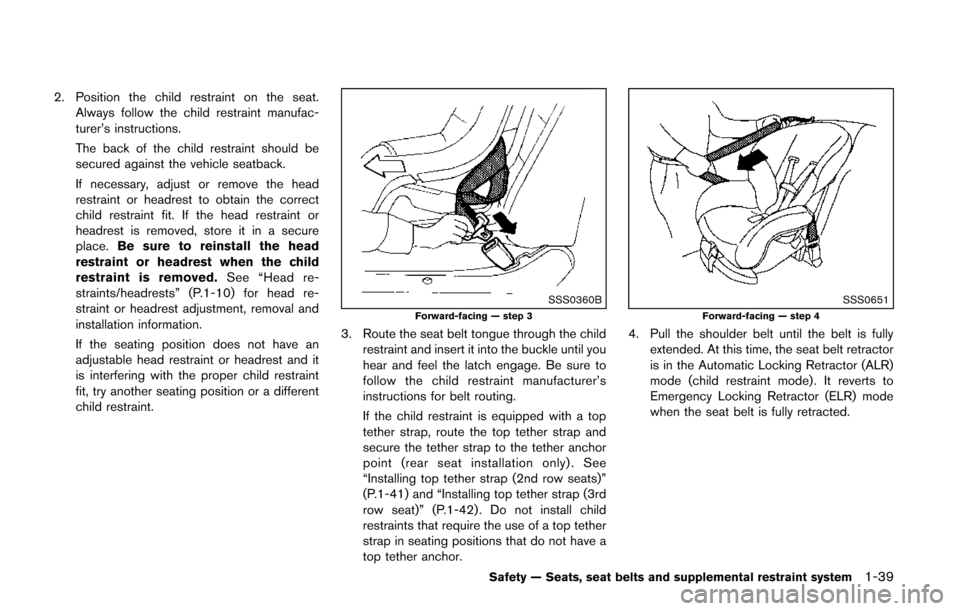
3. Route the seat belt tongue through the child restraint and insert it into the buckle until you
hear and feel the latch engage. Be sure to
follow the child restraint manufacturer’s
instructions for belt routing.
If the child restraint is equipped with a top
tether strap, route the top tether strap and
secure the tether strap to the tether anchor
point (rear seat installation only) . See
“Installing top tether strap (2nd row seats)”
(P.1-41) and “Installing top tether strap (3rd
row seat)” (P.1-42) . Do not install child
restraints that require the use of a top tether
strap in seating positions that do not have a
top tether anchor.
SSS0651Forward-facing — step 4
4. Pull the shoulder belt until the belt is fullyextended. At this time, the seat belt retractor
is in the Automatic Locking Retractor (ALR)
mode (child restraint mode) . It reverts to
Emergency Locking Retractor (ELR) mode
when the seat belt is fully retracted.
Safety — Seats, seat belts and supplemental restraint system1-39
Page 59 of 482
1-42Safety — Seats, seat belts and supplemental restraint system
using the damaged anchorage, and a
child could be seriously injured or killed
in a collision.
First, secure the child restraint with the LATCH
lower anchors or the seat belt, as applicable.
1. If necessary, raise or remove the head restraint to position the top tether strap over
the top of the seatback. If the head restraint
is removed, store it in a secure place. Be
sure to reinstall the head restraint when the
child restraint is removed. See “Head
restraints/headrests” (P.1-10) for head re-
straint adjustment, removal and installation
information.
2. Secure the tether strap to the tether anchor point on the back of each seatback behind
the child restraint.
3. Tighten the tether strap according to the manufacturer’s instructions to remove any
slack. Make sure the head restraint does not
contact the top tether strap.
If you have any questions when installing a
top tether strap on the rear seat, consult
your NISSAN dealer for details.
SSS11683rd row seat
INSTALLING TOP TETHER STRAP (3rd
row seat)
WARNING
. In the 3rd row seat, a child restraint
with a top tether strap can only be
used in the center and right out-
board seating position. Do not place
in the left outboard seating position
and attempt to angle the tether
strap to the center or right outboard
position. .
Child restraint anchorages are de-
signed to withstand only those
loads imposed by correctly fitted
child restraints. Under no circum-
stances are they to be used to
attach adult seat belts, or other
items or equipment to the vehicle.
Doing so could damage the child
restraint anchorages. The child re-
straint will not be properly installed
using the damaged anchorage, and
a child could be seriously injured or
killed in a collision.
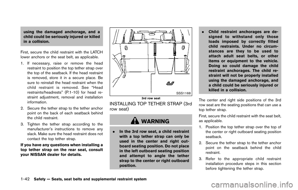
The center and right side positions of the 3rd
row seat are the seating positions that can use a
top tether strap.
First, secure the child restraint with the seat belt,
as applicable.
1. Position the top tether strap over the top of the center or right outboard seating position
seatback.
2. Secure the tether strap to the tether anchor point on the seatback behind the child
restraint.
3. Refer to the appropriate child restraint installation procedure steps in this section
before tightening the tether strap.
Page 62 of 482
LRS0454Front passenger position
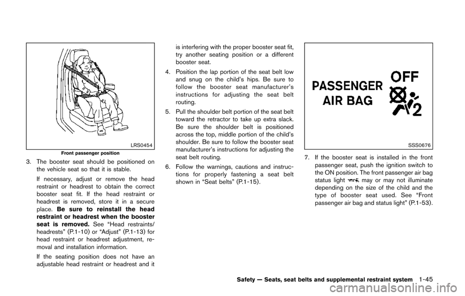
3. The booster seat should be positioned onthe vehicle seat so that it is stable.
If necessary, adjust or remove the head
restraint or headrest to obtain the correct
booster seat fit. If the head restraint or
headrest is removed, store it in a secure
place. Be sure to reinstall the head
restraint or headrest when the booster
seat is removed. See “Head restraints/
headrests” (P.1-10) or “Adjust” (P.1-13) for
head restraint or headrest adjustment, re-
moval and installation information.
If the seating position does not have an
adjustable head restraint or headrest and it is interfering with the proper booster seat fit,
try another seating position or a different
booster seat.
4. Position the lap portion of the seat belt low and snug on the child’s hips. Be sure to
follow the booster seat manufacturer’s
instructions for adjusting the seat belt
routing.
5. Pull the shoulder belt portion of the seat belt toward the retractor to take up extra slack.
Be sure the shoulder belt is positioned
across the top, middle portion of the child’s
shoulder. Be sure to follow the booster seat
manufacturer’s instructions for adjusting the
seat belt routing.
6. Follow the warnings, cautions and instruc- tions for properly fastening a seat belt
shown in “Seat belts” (P.1-15) .
SSS0676
7. If the booster seat is installed in the front
passenger seat, push the ignition switch to
the ON position. The front passenger air bag
status light
may or may not illuminate
depending on the size of the child and the
type of booster seat used. See “Front
passenger air bag and status light” (P.1-53) .
Safety — Seats, seat belts and supplemental restraint system1-45
Page 355 of 482
5-12Starting and driving
.Make sure the area around the vehicle is
clear.
. Check fluid levels such as engine oil, cool-
ant, brake fluid and window washer fluid as
frequently as possible, or at least whenever
you refuel.
. Check that all windows and lights are clean.
. Visually inspect tires for their appearance
and condition. Also check tires for proper
inflation.
. Lock all doors.
. Position seats and adjust head restraints/
headrests.
. Adjust inside and outside mirrors.
. Fasten seat belts and ask all passengers to
do likewise.
. Check the operation of warning lights when
the ignition switch is pushed to the ON
position. (See “Warning/indicator lights and
audible reminders” (P.2-11) .) 1. Apply the parking brake.
2. Move the shift lever to the P (Park) or N
(Neutral) position. (P is recommended.)
The starter is designed not to operate unless
the shift lever is in either of the above
positions.
3. Push the ignition switch to the ON position. Depress the brake pedal and push the
ignition switch to start the engine.
To start the engine immediately, push and
release the ignition switch while depressing
the brake pedal with the ignition switch in
any position.
.If the engine is very hard to start inextremely cold weather or when restart-
ing, depress the accelerator pedal a little
(approximately 1/3 to the floor) and while
holding, crank the engine. Release the
accelerator pedal when the engine starts.
.If the engine is very hard to start becauseit is flooded, depress the accelerator
pedal all the way to the floor and hold it.
Push the ignition switch to the ON
position to start cranking the engine.
After 5 or 6 seconds, stop cranking by
pushing the ignition switch to OFF. After
cranking the engine, release the accel-
erator pedal. Crank the engine with your
foot off the accelerator pedal bydepressing the brake pedal and pushing
the push-button ignition switch to start
the engine. If the engine starts, but fails
to run, repeat the above procedure.
CAUTION
Do not operate the starter for more
than 15 seconds at a time. If the engine
does not start, push the ignition switch
to OFF and wait 10 seconds before
cranking again, otherwise the starter
could be damaged.
4. Warm-up
Allow the engine to idle for at least 30
seconds after starting. Do not race the
engine while warming it up. Drive at
moderate speed for a short distance first,
especially in cold weather. In cold weather,
keep the engine running for a minimum of 2 -
3 minutes before shutting it off. Starting and
stopping the engine over a short period of
time may make the vehicle more difficult to
start.
5. To stop the engine, shift the shift lever to the P (Park) position and push the ignition
switch to the OFF position.
BEFORE STARTING THE ENGINE STARTING THE ENGINE
Page 408 of 482
Lights*:Clean the headlights on a regular basis.
Make sure that the headlights, stop lights, tail
lights, turn signal lights, and other lights are all
operating properly and installed securely. Also
check headlight aim.
Road wheel nuts (lug nuts)*: When checking
the tires, make sure no wheel nuts are missing,
and check for any loose wheel nuts. Tighten if
necessary.
Tire rotation*: Tires should be rotated every
5,000 miles (8,000 km) .
Tires*: Check the pressure with a gauge often
and always prior to long distance trips. If
necessary, adjust the pressure in all tires,
including the spare, to the pressure specified.
Check carefully for damage, cuts or excessive
wear.
Tire Pressure Monitoring System (TPMS)
transmitter components: Replace the TPMS
transmitter grommet seal, valve core and cap
when the tires are replaced due to wear or age.
Wheel alignment and balance: If the vehicle
should pull to either side while driving on a
straight and level road, or if you detect uneven or
abnormal tire wear, there may be a need for
wheel alignment.
If the steering wheel or seat vibrates at normal
highway speeds, wheel balancing may be
needed. For additional information regarding tires, refer
to “Important Tire Safety Information” (US) or
“Tire Safety Information” (Canada) in the War-
ranty Information Booklet.
Windshield:
Clean the windshield on a regular
basis. Check the windshield at least every six
months for cracks or other damage. Have a
damaged windshield repaired by a qualified
repair facility.
Windshield wiper blades*: Check for cracks
or wear if they do not wipe properly.
Inside the vehicle
The maintenance items listed here should be
checked on a regular basis, such as when
performing scheduled maintenance, cleaning
the vehicle, etc.
Accelerator pedal: Check the pedal for
smooth operation and make sure the pedal
does not catch or require uneven effort. Keep
the floor mat away from the pedal.
Brake pedal: Check the pedal for smooth
operation. If the brake pedal suddenly goes
down further than normal, the pedal feels
spongy or the vehicle seems to take longer to
stop, see a NISSAN dealer immediately. Keep
the floor mat away from the pedal.
Brakes: Check that the brakes do not pull the
vehicle to one side when applied. Continuously Variable Transmission (CVT)
P (Park) position mechanism:
On a fairly
steep hill, check that the vehicle is held securely
with the shift lever in the P (Park) position
without applying any brakes.
Parking brake: Check the parking brake
operation regularly. The vehicle should be
securely held on a fairly steep hill with only the
parking brake applied. If the parking brake needs
adjustment, see a NISSAN dealer.
Seat belts: Check that all parts of the seat belt
system (for example, buckles, anchors, adjusters
and retractors) operate properly and smoothly,
and are installed securely. Check the belt
webbing for cuts, fraying, wear or damage.
Seats: Check seat position controls such as
seat adjusters, seatback recliner, etc. to ensure
they operate smoothly and that all latches lock
securely in every position. Check that the head
restraints/headrests move up and down
smoothly and that the locks (if so equipped)
hold securely in all latched positions.
Steering wheel: Check for changes in the
steering conditions, such as excessive free play,
hard steering or strange noises.
Warning lights and chimes: Make sure that
all warning lights and chimes are operating
properly.
Maintenance and do-it-yourself8-3
Page 476 of 482
Fusible links.................................................................. 8-21
G
Garage door opener, HomeLink®
Universal Transceiver.................................................. 2-59
Gas cap......................................................................... 3-30
Gauge .............................................................................. 2-5Engine coolant temperature gauge .................... 2-7
Fuel gauge................................................................ 2-8
Odometer.................................................................. 2-6
Speedometer............................................................ 2-6
Tachometer ............................................................... 2-7
Trip computer........................................................ 2-23
General maintenance ................................................... 8-2
Glove box...................................................................... 2-46
H
Hands-free phone system, Bluetooth®
(models with navigation system).......................... 4-114
Hands-free phone system, Bluetooth®
(models without navigation system) .................... 4-124
Hazard warning flasher switch................................... 6-2
Head restraints/headrests......................................... 1-10
Headlights Aiming control....................................................... 2-36
Bulb replacement................................................. 8-26
Headlight switch................................................... 2-33
Xenon headlights.................................................. 2-33
Heated seats................................................................ 2-38
Heater Engine block heater............................................. 5-34
Heater and air conditioner operation.............. 4-39
HomeLink
®Universal Transceiver ........................... 2-59
Hood release................................................................ 3-25
Hook, Coat hooks....................................................... 2-50 Horn................................................................................ 2-38
Hydraulic pump electric power
steering system............................................................ 5-29
I
Ignition switch (Push-button)..................................... 5-8
Immobilizer system...................................................... 2-29
In-cabin microfilter ...................................................... 4-53
Indicator Dot matrix display................................................. 2-18
Lights....................................................................... 2-16
INFO button.................................................................... 4-9
Inside mirror.................................................................. 3-33
Inspection/maintenance (I/M) test .......................... 9-27
Instrument brightness control .................................. 2-37
Instrument panel................................................. 2-4, 2-43
Intelligent Key system ....................................... 3-3, 3-13 Battery replacement ............................................ 8-23
Intelligent Key system warning light................ 2-14
Key operating range ............................................ 3-15
Key operation ........................................................ 3-16
Warning signals.................................................... 3-19
Interior light control switch ....................................... 2-57
Interior light replacement........................................... 8-27
Interior lights................................................................. 2-56
iPod
®player operation................................... 4-77, 4-96
ISOFIX child restraint................................................. 1-28
J
Jump starting................................................................ 6-10
K
Keyless entry (See remote keyless
entry system)................................................................ 3-21
Keys.................................................................................. 3-3 For Intelligent Key system......................... 3-3, 3-13
L
LabelsAir bag warning labels........................................ 1-59
Air conditioner specification label.................... 9-10
Emission control information label................... 9-10
Engine serial number.............................................. 9-9
F.M.V.S.S./C.M.V.S.S. certification label ........... 9-9
Tire and Loading Information label ....... 8-31, 9-10
Vehicle identification number (VIN) .................... 9-8
LATCH system............................................................. 1-28
License plate, Installing front license plate .......... 9-11
Lift gate.......................................................................... 3-26
Light Air bag warning light........................................... 1-59
Bulb replacement................................................. 8-25
Cargo lights........................................................... 2-58
Fog light switch.................................................... 2-38
Headlight switch................................................... 2-33
Headlights bulb replacement............................ 8-26
Indicator lights....................................................... 2-16
Interior light control switch ................................ 2-57
Interior lights.......................................................... 2-56
Map lights .............................................................. 2-56
Mood lights............................................................ 2-58
Replacement.......................................................... 8-25
Vanity mirror lights ............................................... 2-58
Warning/indicator lights and
audible reminders................................................. 2-12
Xenon headlights.................................................. 2-33
10-3