2014 NISSAN QASHQAI steering
[x] Cancel search: steeringPage 98 of 338

lowered using the switch located on the driver’s
side of the instrument panel, next to the steering
wheel.
The higher the number designated on the switch,
the lower the axis.
When travelling with no heavy load on a flat road,
select position 0.
AUTOMATIC AIMING CONTROL (LED
headlights)
Vehicles with LED headlights are equipped with an
automatic levelling system. The headlight axis is con-
trolled automatically.
NISSAN recommends consulting local regulations
on the use of lights.To clean the headlights, pull the windscreen washer
switch towards you while the headlight switch is in
the
position and the ignition switch is in the ON
position.
NOTE
The headlight cleaner will automatically operate
every fifth operation of the wiper and washer
switch.
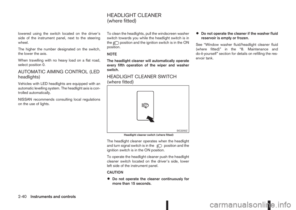
HEADLIGHT CLEANER SWITCH
(where fitted)
The headlight cleaner operates when the headlight
and turn signal switch is in theposition and the
ignition switch is in the ON position.
To operate the headlight cleaner push the headlight
cleaner switch located on the driver’s side, lower
left side of the instrument panel.
CAUTION
•Do not operate the cleaner continuously for
more than 15 seconds.
•Do not operate the cleaner if the washer fluid
reservoir is empty or frozen.
See “Window washer fluid/headlight cleaner fluid
(where fitted)” in the “8. Maintenance and
do-it-yourself” section for details on refilling the res-
ervoir tank.
SIC2255ZHeadlight cleaner switch (where fitted)
HEADLIGHT CLEANER
(where fitted)
2-40Instruments and controls
Page 99 of 338

To sound the horn, push the centre pad areaj1of
the steering wheel.The front seats are warmed by built-in heaters.
The switches are located on the centre console and
can be operated independently from each other (
jA
for the left-hand side seat,jB for the right-hand side
seat).
1. Turn the ignition switch to the ON position.
NOTE
The seat heater can only be activated when
the ignition switch is in the ON position.
2. Start the engine.
3. Select the heat range:
•Press the forward part of the switch (HI)j1
to activate the “HIGH” heat setting.
•Press the rear part of the switch (LO)j2to
activate the “LOW” heat setting.
•For no heat, the switch has a central “OFF”
position between “HIGH” and “LOW”.4. The seat heater switches illuminate when either
heat setting is selected and will remain on as
long as the switch is on.
5. When the vehicle’s interior has warmed-up, or
before you leave the vehicle, be sure to turn the
seat heater system off.
CAUTION
•Do not use the seat heater system for a long
period of time when the engine is not running,
otherwise the battery could run down.
•Do not put anything on the seat that insulates
the heat, such as a blanket, cushion, seat
cover, etc. Otherwise, the seat may overheat.
•Do not place anything hard or heavy on the
seat or pierce it with a pin or similar object.
This may damage the heater.
•Any liquid spilled on a heated seat should be
removed immediately with a dry cloth.
•When cleaning the seat, never use benzine,
thinner or any similar materials.
•If any abnormalities are found or the heating
does not operate, turn off the switch and have
the system checked by a NISSAN dealer or
qualified workshop.
NIC2198NIC2199
HORN SEAT HEATING (where fitted)
Instruments and controls2-41
Page 111 of 338

3Pre-driving checks and adjustmentsPre-driving checks and adjustments
Keys ........................................................................ 3-2
NISSAN Anti-Theft System (NATS)* key ............. 3-2
Intelligent Key (where fitted)................................ 3-2
Key number ........................................................ 3-3
New keys ........................................................... 3-3
Emergency/mechanical key (Intelligent Key
models) .............................................................. 3-3
Integrated keyfob/remote control system .................. 3-4
Switching from Convenience mode to
Anti-hijack mode (where fitted) ............................ 3-5
Using the remote keyless entry system ................ 3-5
Locking the doors ............................................... 3-5
Unlocking the doors ............................................ 3-5
Keyfob operation failure ...................................... 3-5
Intelligent Key system (where fitted) ......................... 3-6
Intelligent Key operating range ............................ 3-6
Using Intelligent Key system................................ 3-6
Locking/unlocking .............................................. 3-7
Starting the engine with the Intelligent Key .......... 3-8
Door locks ............................................................... 3-8
Super Lock system (RHD models) ...................... 3-8
Locking/unlocking with the key (vehicle dead
battery) ............................................................... 3-9Inside door handle .............................................. 3-10
Power door lock switch ...................................... 3-10
Child safety lock — rear doors............................ 3-11
Back door lock ................................................... 3-11
Security system ....................................................... 3-12
Alarm system (where fitted) ................................ 3-12
NISSAN Anti-Theft System (NATS)..................... 3-13
Bonnet release ........................................................ 3-14
Fuel filler lid ............................................................. 3-15
Fuel filler lid opener lever .................................... 3-15
Fuel filler cap ...................................................... 3-15
Parking brake switch ............................................... 3-16
Driving away when towing a trailer ...................... 3-17
Steering wheel......................................................... 3-18
Sun visors ............................................................... 3-18
Mirrors..................................................................... 3-18
Inside rear-view mirror ........................................ 3-18
Automatic anti-dazzling inside mirror (where
fitted).................................................................. 3-19
Outside rear-view mirrors.................................... 3-19
Vanity mirror ....................................................... 3-20
Page 128 of 338

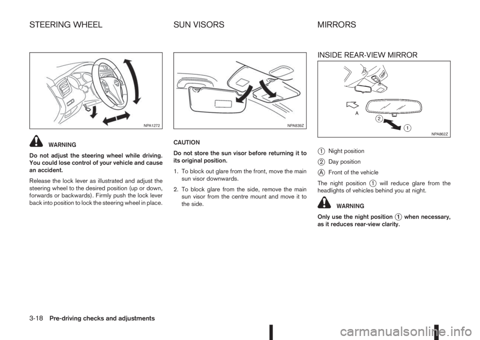
WARNING
Do not adjust the steering wheel while driving.
You could lose control of your vehicle and cause
an accident.
Release the lock lever as illustrated and adjust the
steering wheel to the desired position (up or down,
forwards or backwards). Firmly push the lock lever
back into position to lock the steering wheel in place.CAUTION
Do not store the sun visor before returning it to
its original position.
1. To block out glare from the front, move the main
sun visor downwards.
2. To block glare from the side, remove the main
sun visor from the centre mount and move it to
the side.
INSIDE REAR-VIEW MIRROR
j
1Night position
j2Day position
jAFront of the vehicle
The night position
j1 will reduce glare from the
headlights of vehicles behind you at night.
WARNING
Only use the night position
j1 when necessary,
as it reduces rear-view clarity.
NPA1272NPA839Z
NPA862Z
STEERING WHEEL SUN VISORS MIRRORS
3-18Pre-driving checks and adjustments
Page 131 of 338

4Display screen, heater and air conditioner,
and audio systemDisplay screen, heater and air conditioner,
and audio system
Safety precautions ................................................... 4-2
Rear-view monitor (where fitted)............................... 4-2
How to read the displayed lines .......................... 4-3
Rear-view monitor setting.................................... 4-3
Operating tips..................................................... 4-3
Around View Monitor (where fitted) .......................... 4-4
Operation ........................................................... 4-7
Guide lines ......................................................... 4-7
Difference between predictive and actual
distances ............................................................ 4-9
Moving object detection (MOD) .......................... 4-12
How to adjust the screen view ............................ 4-13
Around View Monitor settings ............................. 4-13
Operating tips..................................................... 4-13
Vents ....................................................................... 4-14
Side and centre vents ......................................... 4-14
Heater and air conditioner operation ........................ 4-15
Manual air conditioner......................................... 4-16
Automatic dual zone air conditioner (where
fitted).................................................................. 4-20
Audio system ........................................................... 4-23Audio operation precautions ............................... 4-23
Antenna .............................................................. 4-23
FM AM radio with CD player (where fitted) .............. 4-24
Audio main operation .......................................... 4-25
Radio operation .................................................. 4-25
SETUP button .................................................... 4-26
Compact Disc (CD) operation ............................ 4-28
AUX socket ........................................................ 4-30
USB Memory operation (where fitted) ................. 4-30
iPod® player operation (where fitted) .................. 4-31
Bluetooth® operation.......................................... 4-32
NissanConnect (where fitted)................................... 4-38
Steering wheel switch for audio control (where
fitted) ....................................................................... 4-38
Main operation .................................................... 4-38
Mobile phone integration for FM AM radio with
CD player (where fitted)........................................... 4-39
Bluetooth® mobile phone feature ........................ 4-39
Hands-free telephone control .............................. 4-42
Steering wheel switches (where fitted)................ 4-44
Car phone or CB radio ............................................ 4-45
Page 138 of 338

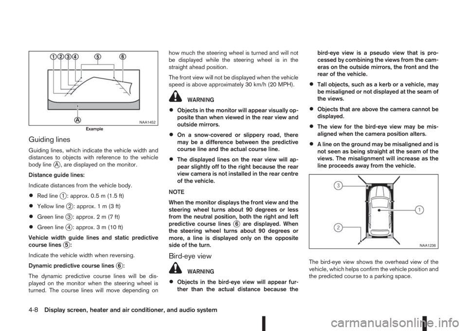
Guiding lines
Guiding lines, which indicate the vehicle width and
distances to objects with reference to the vehicle
body line
jA , are displayed on the monitor.
Distance guide lines:
Indicate distances from the vehicle body.
•Red linej1 : approx. 0.5 m (1.5 ft)
•Yellow linej2 : approx.1m(3ft)
•Green linej3 : approx.2m(7ft)
•Green linej4 : approx. 3 m (10 ft)
Vehicle width guide lines and static predictive
course lines
j5:
Indicate the vehicle width when reversing.
Dynamic predictive course lines
j6:
The dynamic predictive course lines will be dis-
played on the monitor when the steering wheel is
turned. The course lines will move depending onhow much the steering wheel is turned and will not
be displayed while the steering wheel is in the
straight ahead position.
The front view will not be displayed when the vehicle
speed is above approximately 30 km/h (20 MPH).
WARNING
•Objects in the monitor will appear visually op-
posite than when viewed in the rear view and
outside mirrors.
•On a snow-covered or slippery road, there
may be a difference between the predictive
course line and the actual course line.
•The displayed lines on the rear view will ap-
pear slightly off to the right because the rear
view camera is not installed in the rear centre
of the vehicle.
NOTE
When the monitor displays the front view and the
steering wheel turns about 90 degrees or less
from the neutral position, both the right and left
predictive course lines
j6 are displayed. When
the steering wheel turns about 90 degrees or
more, a line is displayed only on the opposite
side of the turn.
Bird-eye view
WARNING
•Objects in the bird-eye view will appear fur-
ther than the actual distance because thebird-eye view is a pseudo view that is pro-
cessed by combining the views from the cam-
eras on the outside mirrors, the front and the
rear of the vehicle.
•Tall objects, such as a kerb or a vehicle, may
be misaligned or not displayed at the seam of
the views.
•Objects that are above the camera cannot be
displayed.
•The view for the bird-eye view may be mis-
aligned when the camera position alters.
•A line on the ground may be misaligned and is
not seen as being straight at the seam of the
views. The misalignment will increase as the
line proceeds away from the vehicle.
The bird-eye view shows the overhead view of the
vehicle, which helps confirm the vehicle position and
the predicted course to a parking space.
NAA1452Example
NAA1236
4-8Display screen, heater and air conditioner, and audio system
Page 143 of 338

•The MOD system might detect flowing water
droplets on the camera lens, white smoke
from the exhaust, moving shadows, etc.
•The MOD system may not function properly
depending on the speed, direction, distance
or shape of the moving objects.
•If your vehicle sustains damage to the parts
where the camera is installed, leaving it mis-
aligned or bent, the sensing zone may be al-
tered and the MOD system may not detect
objects properly.
•When the temperature is extremely high or
low, the screen may not display objects
clearly. This is not a malfunction.
Camera maintenance
If dirt, rain or snow accumulates on the camera, the
MOD system may not operate properly. Clean the
camera.
HOW TO ADJUST THE SCREEN
VIEW
To adjust the display brightness of the Around View
Monitor, use the settings described in the sepa-
rately provided NissanConnect owner’s manual.
Do not adjust the settings while the vehicle is mov-
ing. Make sure the parking brake is firmly applied.
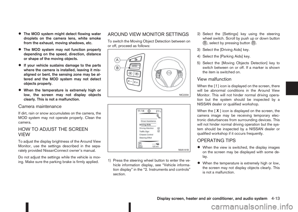
AROUND VIEW MONITOR SETTINGS
To switch the Moving Object Detection between on
or off, proceed as follows:
1) Press the steering wheel button to enter the ve-
hicle information display, see “Vehicle informa-
tion display” in the “2. Instruments and controls”
section.2) Select the [Settings] key using the steering
wheel switch. Scroll by push up or down buttonjB , select by pressing buttonjB.
3) Select the [Driving Aids] key.
4) Select the [Parking Aids] key.
5) Select the [Moving Objects Detection] key to
switch between on or off. If a marker is shown
the item is switched on.
View malfunction
When the [!] icon is displayed on the screen, there
will be abnormal conditions in the Around View
Monitor. This will not hinder normal driving opera-
tion but the system should be inspected by a
NISSAN dealer or qualified workshop.
When the [X] icon is displayed on the screen, the
camera image may be receiving temporary elec-
tronic disturbances from surrounding devices. This
will not hinder normal driving operation but the sys-
tem should be inspected by a NISSAN dealer or
qualified workshop if it occurs frequently.
OPERATING TIPS
•When the view is switched, the display images
on the screen may be displayed with some de-
lay.
•When the temperature is extremely high or low,
the screen may not display objects clearly. This
is not a malfunction.
NIC2204
NAA1418
Display screen, heater and air conditioner, and audio system4-13
Page 168 of 338

For details, see the separately provided NissanCon-
nect Owner’s Manual.
MAIN OPERATION
The audio unit can be operated by using the con-
trols on the steering wheel.
jASeek up/Seek down buttons
jBVolume control buttons
To use the steering wheel audio switch, push the
power “ON” button of the audio unit with the ignition
switch in either the Acc or ON position.
mormSeek up/Seek down
button
– Preset station change (radio mode)
Push the
orbutton to select one of the
preset radio stations.
– Seek tuning (radio mode)
Push and hold the
orbutton to start the
tuning mode. The radio tuner seeks from low to
high or high to low frequencies and stops at the
next broadcasting station.– Track up/down (in CD/USB/iPod/BT Audio
modes)
Push the
orbutton to select the next
track or to return to the beginning of the present
track. Push several times to skip forward or skip
back through the tracks.
mVolume control buttons
Push the—or+ button to adjust the volume
level.LNV2389Z
NAA1383
NISSANCONNECT (where fitted) STEERING WHEEL SWITCH FOR AUDIO CONTROL (where fitted)
4-38Display screen, heater and air conditioner, and audio system