Page 233 of 314
![NISSAN GT-R 2014 R35 Multi Function Display Owners Manual 8-24Voice recognition
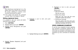
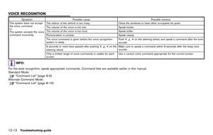
INFO:
With [Continuous Learning] set to on, the
system does not go back to the command
list screen, allowing to continue voice
command learning by the system.
12. If the system h NISSAN GT-R 2014 R35 Multi Function Display Owners Manual 8-24Voice recognition
INFO:
With [Continuous Learning] set to on, the
system does not go back to the command
list screen, allowing to continue voice
command learning by the system.
12. If the system h](/manual-img/5/367/w960_367-232.png)
8-24Voice recognition
INFO:
With [Continuous Learning] set to on, the
system does not go back to the command
list screen, allowing to continue voice
command learning by the system.
12. If the system has learned the command correctly, “None” will change to “Stored”.
Editing registered items
It is possible to edit user names and select
learning function settings.
1. Push .
2. Highlight [Others] and push .
3. Highlight [Voice Recognition] and push .
4. Highlight [Speaker Adaptation] and push
.
5. Highlight a user to edit, and push.
6. Highlight [Setting] and push .
7. Highlight an item to edit, and push
.
Setting items
.[Edit User Name]:
Edit the user name.
.[Delete Voice Data]:Reset the user voice that the voice
recognition system has learned.
.[Continuous Learning]:Have the system learn the voice com-
mands of the user in succession, without
selecting commands one by one.
VOICE COMMAND EXAMPLES
To use the voice recognition function, speaking
one command is sometimes sufficient, but at
other times it is necessary to speak two or more
commands. As examples, some additional basic
operations by voice commands are described
here.
Page 234 of 314

Example 1: Switching map to 2D
(Plan View) mode
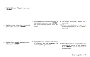
1. Push<>located on the steering wheel.
2. The system announces, “Please say a command”.
3. After the tone sounds and the icon on the screen changes from [
]to[], speak
“Plan View Map”.
4. Voice feedback will be provided when the command is accepted, and the map is
displayed in 2D (Plan View) .
Example 2: Setting destination
using places list
1. Push <>located on the steering wheel.
2. The system announces, “Please say a command”.
3. After the tone sounds and the icon on the screen changes from [
]to[], speak
“Places”.
4. If a route is already set, choose “Near Current Location”, “Along Route” or “Near
Destination”. 5. After the tone sounds and the icon on the
screen changes again, speak “Along Route”.
6. Voice feedback will be provided when thecommand is accepted, and the list of places
of interest categories appears.
7. After the tone sounds and the icon on the screen changes again, speak “Two”.
8. Voice feedback will be provided when thecommand is accepted, and the list of places
of interest in the category specified in the
previous step appears.
Voice recognition8-25
Page 235 of 314
8-26Voice recognition
9. After the tone sounds and the icon on thescreen changes again, speak “One”.
10. Voice feedback will be provided when thecommand is accepted, and the system
starts calculating a route to the selected
facility.
Example 3: Setting destination by
street address
1. Push <>located on the steering wheel. 2. The system announces, “Please say a
command”.
3. Speak “Address”.
4. Speak the name of the state, “California”.
5. Speak the name of the city, “Gardena”.
6. Speak the name of the street, “South Figueroa street”.
INFO:
Speak the street name precisely including
boulevard, way, north, south, etc. In Alter-
nate Command Mode, the system does not
recognize abbreviated names when they are
spoken. In this case, the system does not
accept “Figueroa street” or “Figueroa”.
Page 236 of 314
7. Voice feedback will be provided when thecommand is accepted, and the list of street
names appears.
8. After the tone sounds and the icon on the screen changes again, speak “One”.
9. Speak the house number.
“How to speak numbers” (page 8-17)
INFO:
If the house number is unknown, speak “No
house number”.
10. To confirm the destination location on the map, speak “Show Map”. To calculate a
route, speak “Calculate Route”.
Voice recognition8-27
Page 237 of 314
8-28Voice recognition
MEMO
Page 238 of 314
9 Monitor system
RearView monitor....................................................................... 9-2How to read displayed lines ............................................. 9-2
About RearView Monitor .................................................... 9-3 How to park with predicted course lines ........................... 9-5
Operating tips ..................................................................... 9-6
Camera settings ........................................................................\
9-7
Page 239 of 314

9-2Monitor system
When the shift lever is shifted into the "R"
(Reverse) 
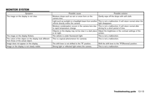
position, the monitor display shows
the view to the rear of the vehicle.
The system is designed as an aid to the driver in
detecting large stationary objects to help avoid
damaging the vehicle. The system will not detect
small objects below the bumper and may not
detect objects close to the bumper or on the
ground.
WARNING
.The RearView Monitor is a conve-
nience but it is not a substitute for
proper backing up. Always turn and
check that it is safe to do so before
backing up. Always back up slowly.
. Objects viewed in the RearView
Monitor differ from actual distance
because a wide-angle lens is used.
Objects in the RearView Monitor
will appear visually opposite like
ones viewed in the inside and out-
side mirrors.
. Make sure that the trunk is securely
closed when backing up.
. Underneath the bumper and the
corner areas of the bumper cannot
be viewed on the RearView monitor because of its monitoring range
limitation.
. Do not put anything on the camera.
The rear view camera is installed
above the license plate.
. When washing the vehicle with
high-pressure water, be sure not to
spray it around the camera. Other-
wise, water may enter the camera
unit causing water condensation on
the lens, a malfunction, fire or an
electric shock.
. Do not strike the camera. It is a
precision instrument. Otherwise, it
may malfunction or cause damage
resulting in a fire or an electric
shock.
CAUTION
There is a plastic cover over the camera.
Do not scratch the cover when cleaning
dirt or snow from the cover.
HOW TO READ DISPLAYED LINES
Guiding lines which indicate the vehicle width
and distances to objects with reference to the
bumper line
*Aare displayed on the monitor.
Distance guide lines:
Indicate distances from the bumper.
. Red line
*1: approx. 1.5 ft (0.5 m)
. Yellow line
*2: approx. 3 ft (1 m)
. Green line
*3: approx. 7 ft (2 m)
. Green line
*4: approx. 10 ft (3 m)
Vehicle width guide lines
*5:
Indicate the vehicle width when backing up.
REARVIEW MONITOR
Page 240 of 314

Predicted course lines*6:
Indicate the predicted course when backing up.
The predicted course lines will be displayed on
the monitor when the shift lever is in the "R"
(Reverse) position and the steering wheel is
turned. The predicted course lines will move
depending on how much the steering wheel is
turned and will not be displayed while the
steering wheel is in the neutral position.
How to adjust RearView screen
To adjust the Brightness, Tint, Color, Contrast
and Black Level of the RearView Monitor, press
with the RearView Monitor on,
select the "Display" key on the screen and select
the item key and adjust the level using the center
dial.
Do not adjust the Brightness, Tint, Color,
Contrast and Black Level of the RearView
Monitor while the vehicle is moving.
ABOUT REARVIEW MONITOR
Difference between predicted and
actual distances
The distance guide line and the vehicle width
guide line should be used as a reference only
when the vehicle is on a level, paved surface.
The distance viewed on the monitor is for
reference only and may be different from the
actual distance between the vehicle and dis-
played objects. Backing up on a steep uphill:
When backing up the vehicle up a hill, the
distance guide lines and the vehicle width guide
lines are shown closer than the actual distance.
For example, the display shows 3 ft (1.0 m) to
the place
*A, but the actual 3 ft (1.0 m)
distance on the hill is the place
*B. Note that
any object on the hill is further than it appears on
Monitor system9-3